Note: Descriptions are shown in the official language in which they were submitted.
CA 02445369 2003-10-17
LOCALIZATION MECIiANISM FOIL AN
MItI C010~IPATI~LE ~IOPSI' DEVICE
Cross Deference to Related A~t>:lrcations
[0001] The present application cross references and incorporates by reference
copending US
Serial No. 101171,330, '°LOCALIZATION MECHAI~'ISM FOR AN MRI
COMPATIBLE BIOPSY DE~IICE" filed on June 12. 2002, the disclosure of which is
hereby incorporated by reference in their entirety.
Field of the Invention
[000] The present invention relates, in general to devices for tissue sampling
and, more
particularly, to a device for positioning a biopsy probe with respect to a
magnetic
resonance imaging (MRI) device.
Background of the Invention
[0003] The diagnosis and treatment of patients with cancerous tumors, pre-
malignant conditions,
and other disorders has long been an area of intense investigation. N~n-
invasive methods
for examining tissue are palpation, Thermography, PET', SPELT, Nuclear
imaging, X-
ray, MRI, CT. and ultrasound imaging. ~Jhen the physician suspects that tissue
may
contain cancerous cells, a biopsy may be done either in an open procedure or
in a
percutaneous procedure. For an open procedure, a scalpel is used by the
surgeon to
create a large incision in the tissue in order to provide direct viewing and
access to the
tissue mass of interest. Removal of the entire mass (excisional biopsy) or a
part of the
mass (incisional biopsy) is done. For a percutaneous biopsy, a needle-like
instrument is
used through a very small incision to access the tissue mass of interest and
to obtain a
tissue sample for a later examination and analysis. The advantages of the
percutaneous
method as compared to the open method are significant: less recovery time for
the
patient, less pain, less surgical time, lower cost, less risk of injury to
adjacent bodily
CA 02445369 2003-10-17
-2-
tissues such as nerves, and less disfigurement of the patient's anatomy. Use
of the
percutaneous method in combination with artificial imaging devices such as X-
ray and
ultrasound has resulted in highly reliable diagnoses and treatments.
[0004] ~'renerally there are two ways to percutaneously obtain a portion of
tissue from within the
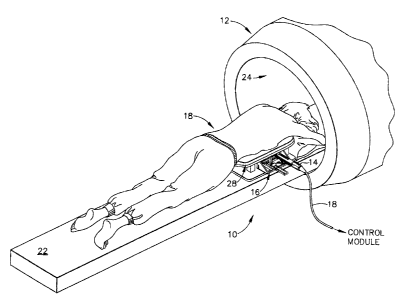
body, by aspiration or by core sampling. Aspiration of the tissue through a
fine needle
requires the tissue to be fragmented into small enough pieces to be withdrawn
in a fluid
medium. The method is less intrusive than other known sampling techniques, but
one
can only examine cells in the liquid (cytology) and not the cells and
structure
(pathology). In core sampling, a core or fragment of tissue is obtained for
histologic
examination, genetic tests, which may be done via a frozen or paraffin
section. The type
of biopsy used depends mainly on various factors present in the patient, and
no single
procedure is ideal for all cases. 1-Iowever, core biopsies seem to be more
widely used by
physicians.
[0005] Recently, core biopsy devices have been combined with imaging
technology to better
target the lesion. A number of these devices have been commercialized. One
such
commercially available product is marketed under the trademark name
MAMMOTOMETM, Ethicon Endo-Surgery, Inc. An embodiment of such a device is
described in U.S. P'atent 1010. 5,526,822 issued to Burbank, et al., on June
18, 1996, and is
hereby incorporated herein by reference.
[0006] As seen from that reference, the instrument is a type of image-guided,
percutaneous,
coring, breast biopsy instrument. It is vacuum-assisted, and some of the steps
for
retrieving the tissue samples have been automated. The physician uses this
device to
capture "actively" (using the vacuum} the tissue prior to severing it from the
body. This
allows the sampling tissues of varying hardness. The device can also be used
to collect
multiple samples in numerous positions about its longitudinal axis, and
without removing
the device from the body. These features allow for substantial sampling of
large lesions
and complete removal of small ones.
CA 02445369 2003-10-17
-3-
[0007) Co-pending application SIN 09/825,899 filed on April 2, 1997, which is
hereby
incorporated herein by reference, described other features and potential
improvements to
the device including a molded tissue cassette housing permitting the handling
and
viewing of multiple tissue samples without physical contact by the instrument
operator.
Another described therein is the interconnection of the housing to the
piercing needle
using a thumbwheel, to permit the needle to rotate relative to the housing,
the preventing
the vacuum tube from wrapping about the housing. During use, the thumbwheel is
rotated so that the device rotates within the lesion, and samples can be taken
at different
points within the lesion.
[0008] In actual clinical use for breast biopsy the instrument (probe and
driver assembly) is
mounted to the three axis-positioning head of an x-ray imaging machine. The
three axis-
positioning heads is located in the area between the x-ray source and the
image plate.
The x-ray machines are outfitted with a computerized system which requires two
x-ray
images of the breast be taken with the x-ray source at two different positions
in order for
the computer to calculate x, y and z axis location of the suspect abnormality.
In order to
take the stereo x-ray images the x-ray source must be conveniently movable..
The x-ray
source therefore is typically mounted to an arm which, at the end opposite the
x-ray
source, is pivotally mounted to the frame of the machine in the region of the
image plate.
[0009] Recently, there has been a need for a hand held core sampling biopsy
device. This need
has been fulfilled by Ethicon-Endo Surgery in L,r.S. Patent 6,086,544 issued
on July 1 l,
2000, which is hereby incorporated herein by referenceo This aforementioned
patent
discloses a hand held MAMMOTOMETM that may be held approximately parallel to
the
chest wall of the patient for obtaining tissue portions close to the chest
wall than may be
obtained when using an instrument that may be obtained when using an
instrument that is
mounted is manipulated by the operator's hand rather than by an
electromechanical arm.
Thus, the operator may steer the tip of the handpiece on the MAMMOTOMETM with
great freedom towards the tissue mass of interest. The surgeon has tactile
feedback while
doing so and can thus ascertain to a significant, degree, the density and
hardness of the
CA 02445369 2003-10-17
-4-
tissue being encountered. In addition, a hand held MAMMOTOMETM is desirable
because the handpiece on the MAMMOTOMETM may be held approximately parallel to
the chest wall of the patient for obtaining tissue portions closer to the
chest wall than may
be obtained when using an instrument that is mounted to an electromechanical
arm.
[0010) Recently, there has been a desire to use the above described biopsy
devices with MRI
imaging devices instead of x-ray imaging devices. However, existing medical
biopsy
sampling devices use small, multi-lumen probes extensively fabricated mostly
if not
entirely from metal. However, the ability to provide accurate minimally
invasive
diagnosis of suspicious breast lesions hinges on the size of the sample
obtained and
accuracy in placement of the sampling device.
[0011] The metallic nature of these probes has many drawbacks. Typically these
metal probes
are electrically conductive. and often magnetically weak, which interferes
with their use
under MRI guidance. The electrically conductive and magnetically weak nature
of metal
probes often work to create field distortions, called artifacts, on the image.
The image of
the lesion will show the metal probe, and this is problematic because the
image of the
probe can obscure the image of the lesion.
[0012] The small sample size of conventional biopsy needles also presents a
significant
limitation due to the increase in the duration of the procedure. Due to the
tendency for
contrast agent to "wash out°' of suspicious lesions, and the
progressive increase in
enhancement of surrounding non-malignant breast parenchyma, suspicious lesions
may
become indistinguishable to the breast parenchyma within a few minutes. This
limits the
number of samples that can be retrieved using conventional spring-loaded core
biopsy
needles under direct imaging guidance.
[0013) A further problem not infrequently encountered during core needle
biopsy is the
development of a hematoma at the biopsy site during the procedure. An
accumulating
hematoma can be problematic during MRI-guided biopsy because residual contrast
agent
circulating in the hematoma can mimic enhancement in a suspicious lesion. In
addition,
CA 02445369 2003-10-17
_5_
the accumulation of air at the biopsy site can cause susceptibility artifacts
that can
potentially interfere with the fat-suppression MRI techniques at the biopsy
site cavity.
[0014] These limitations of conventional biopsy needles have led several
authors to conclude
that lesions should be at least 1 em in diameter before imaging could confirm
that the
MRI-guided biopsy device was definitely within (as opposed to adjacent to) the
suspicious target. However, the demand for minimally invasive MRI-guided core
biopsy
is greatest for small lesions because they are more common, more difficult to
characterize
on MRI grounds alone. and have the best prognosis if they are found to be
malignant.
[0015] Therefore, there has been a desire to have generally non-metallic
(especially non-
ferromagnetic) biopsy probe of the type described above to eliminate
artifacts. These
needs have been filled by co-pending and commonly-owned application S/N
10!021680,
"AN MRI COMPATIBLE SURGICAL BIOPSY DEVICE" to Huitema et al filed on
December 12, 2001, the disclosure of which is hereby incorporated by reference
in its
entirety. The lack of undesirable artifacts for the disclosed hand-held biopsy
device
allows the accurate placement of the probe. Moreover, disclosed vacuum assist
allows
visualization of the lesion entering a bowl of the probe to confirm accurate
placement, as
well as avoiding problems associated with a hematoma or an air cavity.
Moreover, the
volume and ability to rapidly rotate the open cutting bowl of the probe allows
for
multiple samples in succession without removal of the probe. Thereby, the
duration of
the procedure is reduced.
[0016] However, elimination of the artifact created by the metal probe
entirely is also
problematic because physicians rely extensively on some type of artifact to
notify them
as to where the tip of the probe is relative to the lesion. These needs have
been filled by
co-pending and commonly-owned application and S/N 101021407, entitled "AN MRI
COMPATIBLE BIOPSY DEVICE HAVING A TIP V~HICH LEAVES AN ARTIFACT"
to Rhad et al., filed on December 12, 2001, the disclosure of which is hereby
incorporated by reference in their entirety. Having a target in the cutter at
the distal end
CA 02445369 2003-10-17
-6-
of the probe helps avoid advancing the probe through the chest cavity as well
as
accurately placing the bowl of the probe adjacent to the suspicious tissue for
drawing into
the cutting bowl.
[0017] While the aforementioned hand-held MRI compatible biopsy devices
provide many
advantages, opportunities exist for improvements and additional clinical
functionality.
For instance, the hand-held biopsy device presents a long, external handle
that is
inappropriate for closed magnet MRI machines. Furthermore, while the hand-held
biopsy device allows great freedom in lateral and angular orientation, in some
instances it
is preferable to specifically position the biopsy probe. The MRI machine may
provide
very accurate stereotactic MRI-guided placement information that is only
partially
utilized in inserting the probe. In particular, the hand-held biopsy device is
inserted
through an opening in a compression plate, so some two-dimensional alignment
is
provided. However, the angle and depth of insertion the probe tends to vary,
especially
without continual reimaging of the probe during insertion, which is
particularly
inappropriate for closed MRI magnets.
[0018] Consequently, a significant need exists for a device for accurately
positioning an MRI-
assisted biopsy device.
Brief Summary of the Invention
[0019] The invention provides an apparatus useful for positioning a biopsy
probe.
[0020] In one embodiment the invention provides a localization apparatus for
use in a medical
compression apparatus for positioning a biopsy probe. The localization
apparatus
comprises a compression member containing a plurality of apertures, the
position of the
compression member being adjustable along an axis for providing tissue
compression.
At least two generally parallel, spaced apart supports extend in a direction
generally
parallel to the axis. The apparatus also includes a biopsy probe support, the
position of
which is adjustable along the two spaced apart supports. The biopsy probe
support is
CA 02445369 2003-10-17
7
adapted to support a biopsy probe between the two generally parallel spaced
apart
supports for movement of the biopsy probe in two directions perpendicular to
the axis.
The apparatus can further comprise at least two generally parallel spaced
apart supports
for supporting movement of the biopsy probe in a direction perpendicular to
the axis.
[0021] In one embodiment, the invention provides a localization apparatus
which includes a
compression plate and a biopsy probe support plate. 'The compression plate can
include a
plurality of apertures sized and positioned to permit passage of a biopsy
needle associated
with the biopsy probe. The position of the compression plate can be adjustable
for
providing tissue compression. The biopsy probe support plate can extend
generally
parallel to the compression plate, and the biopsy probe support plate can be
supported for
movement relative to the compression plate. The biopsy support plate is
adapted to
support a biopsy probe assembly for movement in two mutually perpendicular
directions
(e.g. X and Z directions) which are transverse to the direction of movement of
the biopsy
support plate relative to the compression plate (e.g. Y direction).
[0022] The present invention also provides a localization apparatus comprising
a compression
member and a biopsy probe support, wherein the biopsy probe support is
supported for
movement with respect to the compression member, and wherein an apparatus
associated
with the biopsy probe support is adapted to releasably engage a biopsy probe
assembly
and position the biopsy probe assembly in two mutually perpendicular
directions (e.g. X
and Z directions) which are transverse to the direction of movement of the
biopsy probe
support relative to the compression member (e.g. Y direction).
Brief I)escrintion of the Figures
[0023] FIGURE 1 is plan view of a biopsy instrument, mounting fixture, an
Magnetic Resonance
Imaging (MRI) breast coil fixture, and patient support table in working
relationship
outside the confines of an MRI machine.
CA 02445369 2003-10-17
_ g
[0024] FIGURE 2 is a plan view of a biopsy instrument, a localization fixture,
partially cut away
MRI breast coil fixture, patient support table, and in working relationship
and configured
for insertion into a MRI machine.
[0025] FIGURE 3 is a plan view of a localization fixture, partially cut away
MRI breast coil
fixture, patient support table, and a detached probe assembly of the biopsy
instrument
mounted to the localization fixture, in working relationship and configured
for insertion
into the MRI machine.
[0026] FIGURE 4 is an isometric view of the biopsy instrument disassembled
into a biopsy
instrument handle, probe housing, and probe.
[0027] FIGURE 4A is a frontal isometric detail view of an alternative needle
tip of a biopsy
instrument.
[0028] FIGURE 5 is an exploded isometric view of a biopsy instrument handle.
[0029] FIGURE 6 is an exploded isometric view of the probe of the biopsy
instrument of FIG. 4.
[0030] FIGURE 7 is a transverse cross section of the probe of the biopsy
instrument of FIG. 4
along lines 7-7.
[0031) FIGURE 8 is an enlarged isometric view of the interface between the
handle and probe
housing illustrating the visual confirmation elements that indicate the
position of the
distal end of the cutter.
[0032] FIGURE 9 is a fragmentary plan view in partial section of the distal
portion of the handle
and probe housing and asseri~bly, illustrating the disconnect feature with the
cutter
retracted.
[0033] FIGURE 10 is a fragmentary plan view in partial section of the distal
portion of the
handle and probe housing and assembly, illustrating the tolerance take-out
feature and the
disabled disconnect feature when the cutter is advanced.
CA 02445369 2003-10-17
-9-
[0034] FIGURE 11 is an isometric view of the biopsy instrument with the handle
portion
disconnected from a towerlbracket localization fixture and probe assembly.
[0035) FIGURE 12 is an isometric view of the biopsy instrument mounted to the
tower/bracket
localization fixture of FTG. 1 I .
[0036] FIGURE 13 is an exploded isometric view of the tower/bracket
localization version of
the localization fixture and probe assembly of the biopsy instrument.
[0037) FIGURE 14 is a side elevation view of the biopsy instrument in partial
section to
illustrate a tower/bracket support for stabilizing the handle and probe
assembly of the
biopsy instrument.
[0038] FIGURE 15 is a side elevation view of the dual tower support version of
the localization
fixture positioning a detachable probe assembly with its dual lumens closed by
a vacuum
conduit and an obturator stylet.
[0039] FIGURE 16 is an isometric view of the biopsy instrument mounted to a
dual tower
localization fixture.
[0040) FIGURE 17 is an isometric view of the slide plate of a localization
fixture guiding a
scissors support in a lowered position for vertically orienting a biopsy
instrument.
[0041) FIGURE 18 is an isometric view of the slide plate of a localization
fixture guiding the
scissors support in a raised position for vertically orienting a biopsy
instrument.
[0042] FIGURE 19 is a sequence of clinical operations for using the detachable
MRI-guided
biopsy instrument of FIG. 1 in both open and closed MRI machines.
[0043) FIGURE 20 is an isometric view of a tip protector mounted onto a needle
tip of the
detachable probe assembly of FIG. I I.
[0044) FIGURE 21 is an isometric detail view of the trip protector of FIG. 20.
CA 02445369 2003-10-17
ID -
[0045] FIGURE 22 is an isometric view of one embodiment of a localization
mechanism
according to the present invention.
[0046] FIGURE 23 is an isometric view of an alternative embodiment of a
localization
mechanism according to the present invention.
[0047] FIGURE 24 is an isometric view of a biopsy mount employing a ball
detent mechanism
for releasably engaging a biopsy probe assembly.
[0048] FIGURE 25 is a cut away isometric view of a three position locking
clamp.
[0049] FIGURE 26 is an isometric illustration of the localization mechanism of
Figure 22
illustrating sliding a compression plate along a Y axis for compressing
tissue.
[0050] FIGURE 27 is perspective illustration of the localization mechanism of
Figure 22
showing a compression plate locked into position upon movement of a biopsy
probe
support plate relative to the compression plate along the Y axis.
Detailed Description of the Invention
[0051] FIGURES 1 through 2I and the accompanying description are taken from
the above
referenced US Patent Application "Localization Mechanism for an MRI Compatible
Biopsy Probe Device" Serial Number IO/171,330 filed June I2, 2002.
[0052] FIG. 1 depicts a core biopsy instrument system YO that is vacuum
assisted, detachable,
and compatible with use in a Magnetic Resonance Imaging (MRI) machine, such as
the
depicted closed MRI machine I2. In the illustrative embodiment, the core
biopsy
instrument system IO includes an MRI-compatible biopsy tool 14 that is
selectably
attached to a localization mechanism or fixture 16 to accurately and rapidly
perform core
biopsies of breast tissue with a minimum of insertions of a biopsy probe. A
control
module (not shown) senses encoder position signal and switch signals from the
biopsy
tool 14 and provides mechanical and vacuum power to the biopsy tool 14 via
power cord
18.
CA 02445369 2003-10-17
-11-
[0053 With reference to FIGS. 1-2, a patient 20 is lying prone upon a patient
support table 22,
depicted in FIG. 1 as removed from a magnet bore 24 of the MRI machine 12. The
patient's chest rests upon a top surface 26 of a chest support 28, the top
surface 24 having
openings 30, 32 for allowing the patient's breasts to hang downward for
imaging and
treatment. With particular reference to FIG. 2, the right opening 30 is
depicted with the
localizer fixture i6 laterally positioned to cooperate with a medial
compression plate (not
shown) to IongitudinaIly fix and compress the patient's right breast. Antenna
elements
(not shown) are placed about the opening 30 to detect radio frequency (RF)
signals
emanated from breast tissue induced by a strong magnetic field from the MRI
bore 24.
The chest support 28, localization fixture 16, and antennas are is generally
termed a
breast coil 34.
[0054] The biopsy tool 14 includes a biopsy handle 36 that attachable to a
probe assembly 38.
The localization fixture 16 accurately positions the probe assembly 38 for
stereotactic
MRI-guided biopsy procedures for a specific biopsy site location for a distal
tip 40 of the
probe assembly 38. This location is identified by an %-axis coordinate that is
horizontal
and longitudinal with respect to the patient (depicted as right to left in
FIGS. 1-2). A Z-
axis is defined as the vertical height, with the X and Z axis orthogonally
defined on a
lateral compression plate 42 of the localization fixture 16, the lateral
compression plate
42 cooperating with the medial compression plate (not shown) to fix and
compress the
patient's breast. This location is also defined in terms of depth of
insertion, or Y-axis,
which is depicted as up and down in the FIGS. 1-2. A probe assembly mounting
device
44 connects to a probe housing 46 of the biopsy tool 14.
[0055] The mounting device 44 includes alignment positioning guides (described
in more detail
below) to orient the probe housing 46, and hence the probe assembly 38, to the
desired X-
Y-Z coordinate. For instance, a depth slide 48 allows mounting of the probe
assembly 38
with the distal tip 40 extends outside of the opening 30 and lateral
compression plate 42.
Thereafter, the probe assembly 38 is guided along the Y-axis by the depth
slide 48 while
maintaining the selected X-Z-axes c~ordinates. In addition, the mounting
device 44
CA 02445369 2003-10-17
- 12-
advantageously supports the biopsy handle 36 when attached to the probe
assembly 38 as
depicted in FIG. 2 to maintain the angle of insertion of the probe assembly
38. The probe
housing 46 provides access to the interior of the probe assembly 38 via a
vacuum lumen
access conduit 50 for draining fluids, inserting fluids such as anesthetics.
(0056] FIG. 3 depicts the core biopsy instrument system 10 with the biopsy
handle 36 removed
and the depth slide 48 moved inward to allow insertion of the patient support
table 22
into the narrow confines of the MRI magnet bore 24. Moreover, the surgeon may
take
full advantage of the stereotactic coordinates provided by the MRI machine 12,
even if
using a closed magnetic bore 24. In particular, the stereotactic derived
coordinates may
be used even if not actively imaging the probe assembly 38 during insertion.
The
localization fixture 16 enables the surgeon to manually insert the probe
assembly 38 in
depth with an indication of current depth. The surgeon is given tactile
feedback while
doing so and can thus ascertain to a significant degree the density and
hardness of tissue
being encountered. In addition, with the probe assembly 38 maintained in the
correct
location after insertion, the probe assembly 38 provides access for other
diagnostic and
therapeutic tools and fluid treatments.
[0057] Alternatively or in addition, a Y-axis adjustment mechanism may be
incorporated into the
localization fixture 16 to provide mechanical advantage, thereby achieving a
controlled
and deliberate insertion of the probe assembly 38. Moreover, the Y-axis
adjustment
mechanism may incorporate a frictional, ratcheting or locking feature to
prevent
inadvertent movement of the probe assembly 38 after placement at the desired
biopsy
location. Examples of such Y-axis adjustment include but are not limited to a
thumb
wheel in geared communication between the probe assembly mounting device 150
and
the localizer support frame 126.
[0058] FIG. 4 depicts the biopsy tool 14 with the biopsy handle 36 depicted as
readily attached
to the probe housing 46> which in turn is readily attached to the probe
assembly 38. The
probe assembly 38 includes a male cylindrical mating portion 52 presenting a
central
CA 02445369 2003-10-17
-13-
cutter opening 54 on a proximal end that is aligned with the longitudinal
length of a cutter
lumen 56 of an elongated needle 58. The cutter lumen 56 communicates with a
sample
port 60 laterally presented near a needle tip 62 at the distal end of the
needle 58. The
needle tip 62 is for penetrating the soft tissue of a surgical patient. The
needle tip 62 is
sharpened and is preferably made from an MRI compatible resin such as ULTEM or
VECTRA. In the illustrative embodiment, the needle tip 62 is a three-sided
pyramidal
shaped point, although the needle tip 62 configuration may also have other
shapes and/or
inserts. In addition, as in the aforementioned application Ser. No. 10/021407,
entitled
"AN MRI COP,~PATIBLE BIOPSY DEVICE HAVING A TIP WHICH LEAVES AN
ARTIFACT", the illustrative embodiment advantageously includes a material that
leaves
a small, but not troublesome artifact on an MRI scan.
[0059) FIG. 4A depicts a needle tip 62' having a conical shape with a distally
presented X-
shaped slot 63 for receiving a pointed, sharpened blade 65 that reduces the
probe
insertion force into tissue. The blade 65 could be made of titanium, stainless
steel,
nitinol, aluminum, Elgiloy, ceramic, etc. It will be appreciated that other
shapes of
sharpened blade 65 may be used, such as a single pointed surface in a distally
presented
single slot rather than two perpedicularly crossed, pointed surfaces as
depicted.
[0060) It will be appreciated that a cutter element or an obturator stylet is
advanced inside the
cutter lumen 56 to block the sample port 60 during insertion. Once the needle
58 is
positioned, the sample port 60 is exposed to allow tissue to enter. In
particular, a vacuum
may be presented to a "sample bowl" inside the cutter lumen 56 near the sample
port 60
by applying vacuum power through a vacuum chamber lumen 64 that communicates
along the longitudinal length of the needle 58 t~ the male cylindrical mating
portion 52.
In particular, a series of small holes allow gas and fluid to enter the vacuum
chamber
lumen 64 from the sample port 60 but prevent tissue samples from entering.
[0061) Annular rings 66 about the cylindrical mating portion 52 grip and seal
to an interior of a
female cylindrical mating portion 68 on the probe housing 46. Between annular
rings, a
CA 02445369 2003-10-17
- 14-
proximal vacuum port (not shown in FIG. 4) communicates with a vacuum passage
(not
shown) in the probe housing 46. The engagement between the mating portions 52>
68
advantageously allows rotation of the needle 58 with a thumb wheel 70
annularly
presented near the proximal end of the needle 58. The radial opening presented
by the
annual rings 66 maintains communication between the vacuum passage in the
probe
housing 46 and the vacuum chamber lumen 64 regardless of radial orientation of
the
needle 58. Thereby, the sample port 60 may be presented to tissue at any and
all radial
positions about the distal end of the needle 58. With the assistance of
vacuum, a large
volume of tissue may be selectably drawn into the sample bowl for biopsy
sampling.
[0062] The probe housing 46 includes laterally presented attachment prongs 72
for mounting to
the localization fixture 16. In addition, the probe housing 46 presents a
proximally
directed cuboidal engagement member 74 with longitudinally aligned vertical
and
horizontal grooves 76 for flanges 78 from the biopsy handle 36. The probe
housing 46
also receives hooked locking tabs 80, 82 on the distal engaging end of the
biopsy handle
36 for selective locking and unlocking under the influence of a pair of
opposing
depression grips 84, 86 attached to respective tabs 80, 82. 'The biopsy handle
36 includes
a sample window 88 for extracting any tissue sample withdrawn from the cutter
lumen 52
under the influence of a vacuum passing through the cutter, as described in
more detail
below.
[0063] FIG. 5 depicts a disassembled biopsy handle 36 that contains the means
for translating
and rotating a cutter 90 within the cutter lumen 56. It will be appreciated
that two
rotating mechanical power sources are presented to the proximal end of the
biopsy handle
36 through the power cord 18 to provide the independent translation and
rotation
motions. These two rotating mechanical power sources enter through a cord
opening 92
defined between a removable shell 94 and a bottom shell 96, the two held
together by
screws. The removable shell 94 is removed when assembling a power cord 18 to
the
handle 36. A lower gear housing 98 is supported upon the bottom shell 96 and
cooperates with a top shell 100 to constrain movement of an elongate drive
screw 102, an
CA 02445369 2003-10-17
-15-
elongate axial screw 104 and cutter carriage 106. In particular, both screws
102, 104 are
allowed to rotate, positioned parallel to one another and the longitudinal
axis of the cutter
lumen 56. Each screw 102, 104 is driven by a respective power source from the
power
cord 18. The drive screw 102 passes through the carriage 106 and interacts
with
corresponding ridges therein to impart a longitudinal translation
corresponding'to the
direction and rate of rotation of the drive screw 102.
[0064] In some applications, a single rotary power source may be used as an
alternative to two
independent rotating mechanical power sources. A transmission mechanism at the
biopsy
handle 36 may convert the single rotary power source into the two motions,
translation
and rotation. As yet another alternative, the single rotary power source may
directly
supply both a translation and rotary motion. Such a translating and rotating
power cable
would be coupled to the cutter 90 to directly control its movement.
[0065] The cutter 90 is an elongate tube with a sharpened distal end for
cutting tissue presented
within the distal end of the cutter lumen 56. The proximal end of the cutter
90 includes a
cutter gear 108 that is exposed through a gear window 110 of the carriage 106
to mesh
with the axial screw 104 for axial rotation of the cutter 90. A tissue remover
111 is a tube
that is fixedly aligned with the Longitudinal axis to enter the proximal end
of the cutter
90. The tissue remover 111 extends up to the sample window 88 and has a vacuum
selectably applied to it by the control module. Thus, when the cutter 90 is
retracted,
vacuum from the tissue remover 1 I 1 draws the sample to the distal end of the
cutter 90
for retraction to the sample window 88, whereupon the sample encounter the
tissue
remover 111 and is dislodged for exiting the biopsy tool 14.
[0066) The carriage 106 includes distally projected guides 112, 114 that
advantageously take-out
slack between biopsy handle 36 and the probe housing 46, as well as providing
indicia to
the surgeon as to the depth of translation of the cutter 90. Taking out slack
between the
assembled parts of the handle 36 and housing 46 advantageously minimizes the
deadzone
length of the distal end of the needle 58. The cutter 90 should completely
translate past
CA 02445369 2003-10-17
- 16-
the sample port 60 in order to reliably cut a sample. To ensure a full cut,
the cutter 90
should translate the maximum distance expected for the assembly. If variation
exists in
manufacturing tolerances between the engagement components, then a further
distance
has to be included in the cutter lumen 56 distal to the sample port 60 to
accommodate the
over-travel. Thereby, the needle tip 62 must be advanced farther than
desirable in some
instances, preventing placement of the sample port 60 near critical body
tissues. At or
near full travel, the guides 112, 114 contact the probe housing 46, causing
movement of
the housing 46 to its maximum, distal position. Thus, critical dimensioning to
minimize
tolerance build-up is simplified.
[006?] FIG. 5 also depicts a brace 116 and brace arm 118 that are employed in
one version of the
localization fixture 16 to support the weight and maintain the alignment of
the handle 36.
Thereby, flexure of the assembly is avoided that may place a load on the probe
assembly
38, and thus unwanted movement of the needle 58 from the desired biopsy site
location.
[0068] FIGS. 6-7 depict the needle 58 of FIG. 4 and described more fully in
the aforementioned
application Ser. No. 10/021680, entitled "AN MRI CGMPATIBLE SURGICAL BI~PSY
DEVICE". In particular, elongated needle 58 is formed from a left body member
120
and a right body member 121 on either side of the longitudinal axis. The edges
of the
halves 120 and 121 are gated for easy part filling, and the edges are stepped
with ridges
that allow the two halves 120 and 121 to attach together with ease. The two
halves 120,
121 are adhesively attached to one another. A cutter tube liner 122 is
inserted between
the two halves 120, 121 to provide a smooth surface for the cutter 90,
especially by
preventing adhesive from entering the cutter lumen 56 during assembly.
[0069] FIG. 8 shows an enlarged view of the engagement of the handle 36 to the
probe housing
46, with the advanced cutter 90 evident through the window 88. In addition,
the guides
112, 114 are advanced almost into contact with the probe housing 46,
indicating that the
distal end of the cutter 90 is approaching its furthest translation. The
guides 112, 114
contact the probe housing 90 when at or near this extreme to take-out any
tolerance.
CA 02445369 2003-10-17
- 17-
Indicia on the side of the guides 112, 114 may be referenced by the surgeon to
determine
the position of the cutter. Also shown in more detail is hooked locking tabs
80, 82
entering the probe housing 46, the thumb wheel 70 used to rotate the needle
80, and the
vacuum lumen access conduit 50 used to evacuate or otherwise access the vacuum
lumen
64.
[0070] FIGS. 8-10 show that each grip 84, 86 includes a respective inwardly
projecting member
124, I25 that contact the guides 112, 114 when the cutter 90 is distally
advanced, thereby
preventing removal of the handle 36. In FIG. 9, the cutter 90 is retracted,
allowed the
depression of the grips 84, 86, unlocking the hooked locking tabs 80, 82 from
the probe
housing 46. In FIG. 10, cutter carriage 106 is advanced, the guides 112, 114
are
contacting the probe housing 46, thereby removing any longitudinal gap between
the
hooked locking tabs 80, 86 and the probe housing 46.
[0071] . FIGS. 11-14 depicts a localization fixture 16 that includes means for
accurately
positioning the probe assembly 38 and supporting the biopsy handle 36. In
particular, a
localizer support frame 126 is formed from the compression plate 42 in a
hinged,
orthogonal relation to a horizontal slide plate 128, both laterally attached
to one another
by gussets 130, 132. Rods 134, 136 horizontally pass through the compression
plate to
adjustably attach to the medial compression plate (not shown) for compressing
the
patient's breast. Apertures, depicted as parallel rows of slots 138, in the
compression
plate 42 are provided to obtain access to a desired biopsy site location while
providing
enough remaining structure in the compression plate 42 for adeduate contact
with the
gatient's breast. Alternatively, the apertures may be a series of holes
aligned both
vertically and vertically, parallel columns of slots, or a large opening of
other shapes. As
yet a further alternative, portions of the compression plate 42 may be
permeable to allow
an aperture to be formed as needed.
[0072] The desired biopsy site location is stereotactically determined during
an MRI scan with
reference to a fiducial marker 140 that presents a small artifact. The
fiducial marker 140
CA 02445369 2003-10-17
_ 1g _
is contained within a fiducial marker holder 142 that may be placed at a
convenient
location on the compression plate 42, accurately placed with reference to
indents spaced
along the slots 138. Alternatively, the fiducial marker may be embedded or
affixed to the
compression plate 42.
[0073] The localizer support frame 126 defines and provides the guide for
positioning the probe
assembly 38. The X-Y-Z axes are defined with regard to the slots 138 and
compression
plate 42. In particular, the vertical dimension, or Z-axis, and horizontal
dimension, or X-
axis, are defined by the surface of the compression plate 42. The depth
dimension, or Y-
axis, is defined as distance away from the plane of the compression plate 42.
The
horizontal slide plate 128 includes laterally aligned front and back rails
144, 146 for
setting the X-axis coordinate. horizontal indicia 148 along the front rail 144
give the
surgeon an accurate measurement of the position of a probe assembly mounting
device
150.
[0074] A first version of the mounting device 15U is depicted that uses a
single vertical pedestal
152 to position and support the probe assembly 38. In addition, the biopsy
handle 36 is
supported by a brace 154 connected to the proximal underside of the handle 36
to a
handle support rod 156 that is slid through a rod hole 158 to the
corresponding side of the
vertical pedestal 152. The appropriate height for the brace 154 is determined
by selecting
one of a range of slots arrayed along the underside of the handle, thereby
pivoting the
brace 154 about a brace aran 160 whose first end slidably pivots within a slot
162 in the
middle of the brace 154 and second end attaches to the distal end oi~ the
handle 36.
[0075] With the handle 36 detached from the probe assembly 38 as depicted in
FICi. 11, an
obturator stylet 164 is slid into the cutter lumen 56 to close the cutter port
88. The stylet
164 may have radially-oriented through holes near its distal end to maintain
fluid
communication between the vacuum lumen chamber 64 and cutter lumen 56.
Alternatively, the stylet 164 may be partially withdrawn, allowing the cutter
port 88 to be
in fluid communication with the conduit 50
CA 02445369 2003-10-17
- 19-
[007b] A slide 166 includes a grooved underside to horizontally slide on rails
144, 146 of the
slide plate 128. The slide 166 also includes a central channel 168 oriented in
the Y-axis
depth dimension to guide the pedestal 152 as it slides in the Y-axis
direction. Sufficient
range of motion in depth is achieved with a pivoting depth slide 170, aligned
and
pivotally attached to the slide 166. ~Jith the pivoting depth slide 170 in its
lowest,
horizontal position, the pedestal 152 may be slid outevard sufficiently for
the probe
assembly 38 to be out of the compression plate 42. WYith the pedestal 152
distally slid
onto the slide 166, the pivoting depth slide 170 may be pivoted upward or
otherwise
removed. Depth indicia 172 along the central channel 168 give the surgeon an
indication
of the insertion depth of the probe assembly 3$.
[0077] A vertical slide 174 slides on the pedestal 152 for vertical
positioning along the Z-axis,
with a measurement provided by. vertical indicia 176 on the pedestal 152. I-
Ioles I?8 on
each lateral side of the vertical slide 174 allow mounting of the probe
housing 46 on
either side by insertion of attachment probes 72.
[0078] FIGS. 15-16 depict a second version of the mounting device 150 that
uses a second
vertical pedestal 180 in lieu of a brace assembly to support the handle 36.
The probe
housing 46 is also depicted as attached to the opposite side of the first
vertical pedestal
152. A second vertical slide 181 of the second vertical slide 180 advantages
contacts the
first vertical slide 174, as shown in FIG. 16, so that setting the vertical
height for both is
accomplished in one step. Each vertical slide 174, 181 moves in a ratchet
fashion against
its respective vertical pedestal 152, 180, and thus remains in position after
being
separated from one another as shown in FIG. 15. Moreover-, the close nesting
of the two
vertical pedestals 174, 180 enhances the ability to minimize the proximal
displacement of
the localization fixture 16 when used within the close confines of a closed
MRI magnetic
bore 24. It will be further appreciated that the second vertical slide 181
includes a shaped
area that engages the underside of the handle 36 in such a way as to correctly
align the
handle 36 at the same X-axis horizontal dimension as the probe assembly 38.
CA 02445369 2003-10-17
-20-
[0079] FIGS. 17-18 depict a third version of the mounting device 1~0 wherein
the slide 166 and
pedestal 152 are replaced with a scissors table assembly 182 that includes a
first slide 184
for horizontal movement on the slide plate 128. A depth slide 186 is nested
within a top
channel 188 of the first slide 182. With particular reference to FIG. 18, a
pair of scissors
braces 190 are extended when drawn together with a screw I92, thereby
elevating the
depth slide 186 with respect to the first slide 184. It will be appreciated
that the third
version of the mounting device 150 advantageously provides a level support for
both the
detachable probe assembly 38 as well as the biopsy handle 36 without having to
perform
two vertical adjustments, as well as not having to perform two separate
attachments for
each of the handle 36 and probe assembly 38.
[0080] FIG. 19 depicts a sequence of operations, or method 200, for performing
an MRI-guided
breast core biopsy that accurately and quickly performs a core biopsy even in
a closed
MRI. Moreover, the method takes full advantage of the-stereotopic location
information
rendered from the MRI scan to position an MRI compatible core biopsy probe
without
the necessity of continuous imaging of the distal tip of the biopsy probe.
[0081] Prior to performing a clinical breast biopsy, the equipment is
initialized to ensure proper
function. Thus, in block 202, the probe that comprises a needle, thumb wtaeel
and
housing is assembled with the handle. The assembled biopsy tool is connected
via a
power cord to a control module and the system is powered up, initiating power
up logic
in the control module (block 204). Parameters for rotation speed and
translation
distances are loaded. If the control module determines that the system has not
been
powered up recently, such as 60 minutes, ehen initialization logic is
performed. Thus,
translational drivetrain initialization is performed (block 206); rotational
drivetrain
initialization is performed (block 208); and vacuum system initialization is
performed
(block 210). If initialization is not required, then blocks 206-210 are
bypassed.
[0082] Then, the patient's breast is immobilized m the localization mechanism
(block 212) and
the patient is moved into the MRI magnet bore (block 214). An MRI scan is
performed
CA 02445369 2003-10-17
-2I -
to stereotopically locate suspicious tissue with reference to a movable
fiduciary marker
on the localization mechanism (block 216). For a closed NIRI magnet bore, the
patient is
then removed (block 218), which is not necessary far an open bore. Anesthesia
is
administered prior to the minimally invasive vacuum assisted core biopsy
procedure
(block 220). Using the K-Y-Z positioning capabilities of the localization
mechanism, the
positioning guides on the localization mechanism are positioned for insertion
to the
predetermined biopsy site (block 222).
[0083] Optionally, insertion may be enhanced by use of an insertion tool
installed through the
probe assembly 38 (block 224). For instance, an 'ultrasonic cutting tip,
extender, and
outer tube assembly may be inserted through the probe assembly 38 through a
slot in the
needle tip 62, or exiting from the sample port 60 to be snapped onto the
needle tip 62.
This could be accomplished with a. housing on the ultrasonic device that is
configured to
snap onto the needle 58, similarly to how a trocar obturator snaps onto the
trocar cannula.
Then, the ultrasonic tip is energized prior to insertion into the patient.
[0084] The probe assembly is mounted on the localization mechanism (block 226)
at the
designated X-Z coordinate and with the mounting device withdrawn along the
depth axis.
The cutter lumen is sealed with an obturator stylet (block 228), if not
otherwise sealed by
a tool in block 224. The vacuum lumen may be similarly sealed (e.g., stopcock
attached
to vacuum lumen access conduit 50) or be used to aspirate fluid and tissue
during
insertion. Then the probe is advanced along the Y-axis, guided by the
localization
mechanism to avoid misalignment (block 230). Once in place, if an insertion
enhancement tool was installed in block 224, then this tool is withdrawn
through the
cutter lumen of the probe assembly (block 232).
[0085] With the probe in place, various fluid transfers may advantageously
take,place through
the probe assembly (block 234). For example, vacuum may be applied through the
vacuum lumen with the sample port exposed to drain any hematoma or air bubble
formed
at the biopsy site. Treatment fluids may be inserted directly to the biopsy
site, such as
CA 02445369 2003-10-17
-22-
anesthesia or MRI contrast agent. If the patient is to be scanned in a closed
magnet bore,
then the patient is moved back into the bore for scanning (block 236). In
addition,
vacuum may optionally be applied to the biopsy site to draw in suspicious
tissue into the
bowl of the sample port for confirmation prior to cutting the sample (block
238). Then,
the MRI scan is performed to confirm placement of tissue in the bowl of the
probe
assembly, and adjustment of the probe assembly placement and re-scans are
performed as
required (block 240).
[0086] Sample mode is selected through the control module to perform the
sequence of steps to
translate and rotate the cutter according to predetermined settings, with
vacuum assist to
draw in the sample and to retract the sample along with the cutter to the
sample window
(block 244). If more samples at this biopsy site are required for diagnostic
or for
treatment purposes (block 246), then the thumb wheel is rotated to reorient
the sample
port to another angle (block 248), and sample mode is performed again by
returning to
block 244.
[0087] After the core biopsy is performed, the probe assembly provides an
excellent opportunity
for other minimally invasive diagnostic procedures and treatments without the
necessity
for another insertion. If the biopsy handle is installed, such as in an open
MRI magnet
bore, the handle is removed so that the detachable probe assembly may be
accessed
(block 250). Examples of tools that may be inserted through the probe assembly
include:
(1) gamma detectors; (2) energized tunneling tips to reduce tunneling forces;
(3) inserts
to aid in reconstruction of removed tissue (e.g., one or two sided shaver
inserts); (4)
spectroscopy imaging devices; (5) general tissue characterization sensors
{e.g., (a)
mammography; (b) ultrasound, sonography, contrast agents, power Doppler; (c)
PET and
FDG ([Flourine-18J-2-deoxy-2-fluoro-glucose); (d) MRI or NMR, breast coil; (e)
mechanical impedance or elastic modulus; (f) electrical impedance; (g) optical
spectroscopy, raman spectroscopy, phase, polarization, wavelength/frequency,
reflectance; (h) laser-induced fluorescence or auto-fluorescence; (i)
radiation
emission/detection, radioactive seed implantation; (j) flow cytometry; (k)
genomics, PCR
CA 02445369 2003-10-17
-23-
(polymerise chain reaction)-brcal, brca2; (1) proteomics, protein pathway};
(6) tissue
marker sensing device; ('~) inserts or devices for MRI enhancement; (8)
biochips on-a-
stick; (9) endoscope; (10) diagnostic pharmaceutical agents delivery devices;
(11)
therapeutic anti-cancer pharmaceutical agents delivery devices; (12) radiation
therapy
delivery devices, radiation seeds; ( 13) anti-seeding agents for therapeutic
biopsies to
block the release of growth factors and/or cytokines (e.g., chlorpheniramine
(CPA) is a
protein that has been found to reduce proliferation of seeded cancer sells by
75% in cell
cultures.); (14) fluorescent tagged antibodies, and a couple fiber optics to
stimulate
fluorescence fa~om a laser source and to detect fluorescence signals for
detecting
remaining cancer cells; (IS) positive pressure source to supply fluid to the
cavity to aid
with ultrasound visualization or to inflate the cavity to under the shape or
to reduce
bleeding; (16) biological tagging delivery devices (e.g., (a) functional
imaging of cellular
proliferation, neovacularity, mitochondria) density, glucose metabolism; (b)
immunohistochemistry of estrogen receptor, her2neu; (c) genomics, PCR
(polymerise
chain reaction)-brcal, brca2; (d) proteomics, protein pathway); and (17)
marking clips.
[0088] Then, a tissue marker is inserted through the probe assembly so that
subsequent
ultrasonic, X-ray, or MRI scans will identify the location of the previous
biopsy (block
252) and the probe is removed (block 254).
[0089] FIGS. 20-21 depict a tip protector 260 that advantageously protects the
needle tip 62 of
the probe assembly 38 prior to insertion into tissue and simplifies
localization of the
probe assembly 38 in some instances. Furthermore, the tip protector 260 does
not
interfere with pre-clinical setup procedures (e.g., testing for vacuum leaks).
In particular,
the tip protector 260 includes an attachment member 262 with clips onto the
needle 58
without obstructing the sample port 60. A distal portion of the tip protector
completely
encompasses the needle tip 62 with a protection member, depicted as a
hemispheric disk
264, that may be placed in contact with a patient's breast without discomfort.
In addition,
in some applications the hemispheric disk 264 may be comprised of or include
an MRI
artifact producing material, such as those described above. Since the
hemispheric disk
CA 02445369 2003-10-17
-24-
264 is MRI scanned outside of the patient's breast, a stronger artifact may be
presented to
aid in quickly locating the artifact without obscuring the suspected lesion.
[0090] With a fiducial marker integrated into the tip protector 260, there is
potentially one less
step in the localization process for operators that prefer to position
fiducial marker at the
closest insertion point to a suspected lesion prior to insertion.
Procedurally, with the tip
protector 260 in place, the operator would attach the probe assembly 38 onto
the pedestal
152 and move the probe assembly 38 up against the breast tissue in the
vicinity of where
they believe the suspicious tissue to be, based on an earlier diagnostic
image. Next, when
the distance from this fiducial marker to the lesion is calculated, the
"delta°' distances are
based on where the probe is currently positioned. There is a fixed offset
along the Y axis
to account for the distance from the fiducial to the middle of the bowl. The
attachment
member 262 accurately locates the hemispheric disk 264 so that this Y-axis
offset is
predictable. This would be more intuitive because the delta positions are from
where the
probe is currently located.
(0091] Figure 22 provides an isometric schematic illustration of an embodiment
of a fixture
mechanism 316 according to the present invention. The fixture mechanism 316
can
include a base 318, a movable breast compression plate 342 having apertures
for
accommodating a biopsy needle (apertures in the form of parallelel slots 338
in Figure
22), and a probe support plate 352. The probe support plate 352 can be
supported to
move independently of the breast compression plate 342 in the Y direction. A
biopsy
probe assembly 438 (including needle with distal tip 440) can be supported on
probe
support plate 352 to move relative to the probe support plate 352 in the X and
Z
directions, as described in more detail below. The biopsy probe assembly 438
can be
releasably attached to a probe assembly mount 320, such as by a spring loaded
mechanism (e.g. ball detent) or other biasing mechanism for reducing
clearances between
the assembly 438 and the mount 320 (in order to improve positional accuracy of
the
probe). Probe assembly mount 320 in turn can be supported on support plate 352
to
CA 02445369 2003-10-17
-25-
permit movement of mount 320 with respect to support plate 352, as described
more fully
below.
[0092] Still referring to Figure 22, probe support plate 352 can include plate
side portions 353
which are laterally spaced apart in the X direction. A bottom plate portion
355 and a top
bridge 357 extend between the side portions 353 and together with the side
portions 353
define an opening in the support plate 352 through whieh a portion of the
probe assembly
438 can extend.
[0093] Compression plate 342 is supported on slide shafts 372 (which can be
rigidly attached to
or otherwise fixed relative to the base 318) to translate relative to the base
318 in the Y
direction. The Compression plate 342 can be supported by bushings 374A (or
other
suitable bearings) for permitting sliding of the plate 342 on shafts 372. The
bushings can
be disposed in bosses 347 which extend from side portions 343. Bushings 374A
can
extend along shafts 372 to also be disposed within a locking mechanism
associated with
shaft 372, such as releasable clamp locking mechanisms discussed below. Shafts
372
can include splines, a non circular cross-section or have other anti-rotation
features to
prevent rotation of the shaft with respect to the plate 342 and for carrying
torsional loads.
[0094] A Iocking mechanism 376A can be associated with each support shaft 372
to releasably
fix the position of the compression plate 342 in a desired Y location along
the shafts 372.
A suitable locking mechanism is a toggle clamp manufactured by ICE-STAC-CO
Industries of Madision Heights, Michigan. Other suitable locking mechanisms
for
releasably fixing the plate 342 at a desired location along the shafts 372
include, without
limitation, friction locks, set screws, over center clamps, and spring loaded
clamps. In
one embodiment, a locking clamp can include a three position lever, wherein in
an
upright position the lever unclocks the clamp, in a horizontal position the
lever locks the
clamp, and wherein the lever can be depressed against a biasing spring to a
third position
to unlock the clamp while the lever remains depressed.
CA 02445369 2003-10-17
-26-
[0095] The movable breast compression plate 342 can include plate side
portions 343 which are
laterally spaced apart in the X direction. The plate 342 can include a bridge
347 and ribs
349 which extend laterally between the side portions 343 to provide apertures
(slots 338
in Figure 22) for permitting passage of the biopsy needle in the Y direction.
Alternatively, the apertures can be provided in the foam of an array or grid
of openings,
and the apertures can be formed in a separate insert that is attached to plate
342.
[0096] The movable breast compression plate 342 engages two shafts 382 at
bushings 374B.
Bushings 374B are shown disposed in bosses 344. Bosses 344 extend laterally
outwardly from each plate side portion 343 of compression plate 342. Breast
compression plate 342 can slide in the Y direction relative to shafts 382.
Accordingly,
breast compression plate 342 is supported to slide relative to both shafts 372
and shafts
382 in the Y direction. Shafts 382 are generally parallel to, or collinear,
with shafts 372,
and shafts 382 have ends which can be fixed to probe support plate 352. In the
embodiment in Figure 22, shafts 382 are cantileverd from bosses 354 which
extend
laterally outwardly from each plate side portion 353 of the support plate 352.
Sliding
movement of shafts 382 with respect to plate 342 results in motion of plate
352 with
respect to plate 342 in the Y direction. A locking mechanisms 376B can be
associated
with each shaft 382 to releasably fix breast compression plate 342 with
respect shaft 382
(and also with respect to plate 352) in the Y direction. Shafts 382 can have
splines, non
circular cross sections, or otherwise incorporate anti rotation features for
carrying
torsional loads.
[0097] The center to center spacing of shafts 372, labeled 373 in Figure 22,
can be selected to
reduce cocking or misalignment of plate 342 and to accommodate the movement of
probe
assembly 438 in the X direction. In one embodiment, the spacing 373 is at
least about 6
inches, more particularly at least about I~ inches, and still more
particularly at least about
12 inches. The center to center spacing of shafts 382 can be the same as or
different than
the spacing of shafts 372, and in Figure 22 is shown to be greater than the
spacing of
shafts 372.
CA 02445369 2003-10-17
-27-
[0098) Still referring to Figure 22, the probe assembly 438 is supported on
the probe support
plate 352 so that the probe assembly can move in the X and the Z direction
relative to the
plate 352. The probe assembly can be releasably attached to probe mount 320.
The
probe mount, in turn can be supported by a bushing or other bearing device to
permit
sliding of the probe mount 320 on a shaft 392 for translation of the probe
mount 320 and
probe assembly 438 in the X direction. A locking mechanism (not shown)) can be
used
to releasably fix the mount 320 (and so probe assembly 438) at a desired X
direction
location along the shaft 392.
[0099] Shaft 392 can be supported to be movable in the Z direction relative to
plate 352. In
Figure 22, shaft 392 has its opposing ends supported in support blocks 393.
Support
blocks 393 can include bushings or other bearing devices to provide sliding of
the blocks
393 in the Z direction on two generally parallel rails 396. Rails 396 are
fixed to support
plate 352 (one rail 396 associated with each side portion 353 in Figure 22),
and rails 396
extend along their lengths in the Z direction. Accordingly, blocks 393 (and so
shaft 392)
can be positioned along rails 396 to position the probe assembly 438 in a
desired Z
direction location. A locking mechanism (not shown) can be associated with
each
support block 393 to lock the shaft 392 (and so probe assembly 438) in a
desired Z
direction location.
[00100) Figure 23 provides an isometric schematic illustration of another
alternative embodiment
of a fixture mechanism 5I6 according to the present invention. The fixture
mechanism
5I6 can include a base 518, a movable breast compression plate 542 having
parallel slots
538 (through which needle point 640 may pass), and a probe support plate 552
for
supporting a probe assembly 638. Figure 23 also illustrates a medial breast
compression
plate 522 which is positioned in one of a series of opposing slots 526 formed
in the base
5I8. The Y direction position of the plate 522 relative to the frame can be
varied in
discrete intervals by positioning the plate 522 in different pairs of opposing
slots 526.
CA 02445369 2003-10-17
-28-
[~0101] The probe support plate 552 in Figure 23 is supported on two generally
parallel slide
support rails 572. Support plate 552 is slidable on rails 572 relative to the
base 518 in the
Y direction. Support rails 572 can be joined to base 518 along substantially
their entire
length, as shown in Figure 23, to minimize cantilever loads and resulting
positioning
error. In Figure 23, breast compression plate 542 is supported on the same
slide rails
572, and each of the plates 542 and 552 can be positioned along the rails 572
at desired Y
direction locations along the rails. Locking mechanisms (not shown) can be
used to
releasably fix the plates 542 and 552 in desired Y direction positions along
the rails 572.
A biopsy probe assembly 638 (including needle with distal tip 640) is
supported on the
probe support plate 552 to move relative to the plate 552 in the X and Z
directions, as
described more fully below.
[00102] Still referring to Figure 23, probe support plate 552 can include
plate side portions 553
which are laterally spaced apart in the X direction. A bottom plate portion
555 and a top
bridge 557 extend between the side portions 553 and together with the side
portions 553
define an opening in the support plate 552 through which a portion of the
probe assembly
638 can extend. Bosses 554 on each plate portion 553 can include bushings.or
other
suitable bearing devices for sliding support of plate 552 on rails 572.
[00103] The movable breast compression plate 542 can include plate side
portions 543 which are
laterally spaced apart in the X direction. The plate 542 can include a bridge
547 and ribs
which extend laterally between the side portions 543 to provide slots 538.
Alternatively,
the slots can be provided by a separate insert that is attached to plate 542.
In Figure 23,
an insert 642 is shown which includes ribs 649. The insert 642 can slide into
a slot 549
formed through bridge 547, and the insert 642 can engage opposing side slots
550 in the
plate side portions 543. Plates 542 can include bosses 544 extending laterally
outwardly
from side portions 543. Bosses 544 can include bushings for supporting the
plate 542 for
sliding on rails 572.
CA 02445369 2003-10-17
-29-
[00104] Rails 572 can have splines, non circular cross sections, or otherwise
incorporate anti
rotation features. The center to center spacing of rails 572 can be selected
to prevent
cocking of plate 542 and 552 on rails. In one embodiment, the spacing is at
least about 6
inches, more particularly at least about 10 inches, and still more
particularly at least about
12 inches.
j0010~] Still referring to Figure 23, the probe assembly 638 can be releasably
attached to a probe
mount 520, such as by a spring loaded mechanism. Probe mount 520 is supported
on the
probe support plate 552 so that the probe mount and probe assembly can move in
the X
and the Z direction relative to the plate 552. The probe mount 520 can be
supported by a
bearing on one or more shafts 592 (two shafts shown in Figure 23) for
translation in the
X direction. A locking mechanism (not shown) can be used to releasably fix the
probe
mount 520 at a desired X direction location along the shafts 592.
[00106] The shafts 592 can be supported to be movable in the Z direction
relative to plate 552. In
Figure 23, shafts 592 have opposing ends supported in support blocks 593.
Support
blocks .593 can include bushings or other suitable bearing surfaces for
sliding generally
parallel rails 596. Rails 596 are fixed to support plate 552 (one rail 596
associated with
each side portion 553 in Figure 23), and rails 596 extend along their lengths
in the Z
direction. Accordingly, shaft 592 can be positioned along rails 596 to
position the probe
mount 520 and probe assembly 638 in a desired Z direction location. A locking
mechanism (not shown) can be associated with each support block 593 to lock
the shafts
592 (and so probe assembly 638) in a desired Z direction location.
[00107] One or more fiducial markers can be attached to one or both of the
plates 542 and 552 to
present an artifact which is detectable in a magnetic resonance image. In
Figure 23 a
fiducial marker 700 is shown positioned on breast compression plate 542. If
desired,
position encoders can be associated with each axis of motion, and the output
from the
encoders can be transmitted to a receiving source, such as a computer control
and/or a
visual readout display {e.g. an LED display). Position eneoding can be
accomplished
CA 02445369 2003-10-17
_ 30 ..
using any suitable encoding means, including without limitation mechanical,
optical,
laser, or magnetic encoding means. A suitable encoder is an EM1 Optical
Incremental
encoder Module available from US Digital of Vanouver, ~Iashington, USA. A
position
encoder can be associated with each of plates 542 and 552 to identify the Y
position of
the plates' position along rails 572. A position encoder can be associated
with one or
both of blocks 593 to identify the position of the blocks in the Z direction
along rails 596.
A position encoder can be associated with the probe mount 520 to identify the
position of
the mount 520 in the X direction along shafts 592. ~ne portion of the encoder
system
(such as a linear strip with indicia lines) can be attached or otherwise
associated with a
shaft or rail (e.g. rails 572), and another portion of the encoder system
(such as the sensor
read head) can be attached to or otherwise associated with a part moving with
respect to
the shaft or rail (e.g blocks 593). The position information from the encoders
can be used
to determine, transmit, andlor visually display the X, 'Y, and Z position of
the probe
assembly (including needle tip 640).
[00108] In Figure 23, rails 572 provide a first pair of generally parallel,
elongated sliding supports
oriented in a first direction (Y), and rails 596 provide a second pair of
generally parallel,
elongated sliding supports oriented in a second direction (Z) perpendicular to
the first
direction. Biopsy probe support plate 552 is adapted to support the biopsy
probe 638 in a
position that is everywhere between the two parallel rail supports 572 (when
viewed
along the Z axis) and between the two rail parallel supports 596 (when viewed
along the
Y axis), and with biopsy probe 638 being supported on probe mount 520 for
sliding
movement along a third direction (X) perpendicular to the first and second
directions.
Positioning the support rails 572 and 596, one each on each side of probe
assembly 638,
so that the probe assembly is between each pair of generally parallel
supports, can be
helpful in minimizing probe misalignment and positioning inaccuracy.
[00109] In using the apparatus of Figures 23, the patient's breast can be
immobilized in the
localization mechanism by advancing the lateral compression plate along the Y-
axis.
kith the breast relatively immobilized, the patient is moved into the MFZI
magnet bore.
CA 02445369 2003-10-17
-31-
An IvIRI scan of the breast is performed to locate suspicious tissue with
reference to a
fiduciary marker located on the localization mechanism. For a closed 1VII~I
magnet bore,
the patient is then removed from the magnet bare (not necessary for an open
bore). By
scrolling through slice images of the breast, the IvIRI system allows the
clinician to place
a cursor on the suspicious tissue defining the coordinates of that point in
space.
Likewise, the clinician can also select the slice image that contains the
fiducial marker
and place a second cursor on it defining its coordinates. By comparing the two
sets of
coordinates, the relative position between the fiducial marker and the
suspicious tissue
can be calculated. 'The probe assembly 638 can then be mounted on probe mount
520 on
the localization mechanism. Using the X-Y-Z positioning capabilities of the
localization
mechanism, positioning guides on the localization mechanism are positioned at
the
fiducial marker and the X-Y-Z positions are zeroed-out to set the reference
point. The
probe assembly mount 520 is then moved along shafts 592 in the x-axis
direction the
calculated relative distance and its position along the x-axis is fixed with
the locking
mechanism. The probe assembly mount 520 is then moved in the Z direction by
sliding
blocks 593/shafts 592 on rails 596 the calculated relative distance and its
position along
the Z-axis is fixed. Lastly, the probe assembly needle tip 640 is inserted
into the breast by
advancing the probe support plate 552 along the Y-axis on rails 572 the
calculated
relative distance to the predetermined biopsy site and its position is fixed
along the Y-
axis. The actual biopsy is then performed.
[00110) Figure 24 provides an isometric schematic illustration of a biopsy
probe assembly
(designated 938) and a probe mount (designated 820) incorporating a spring
loaded "ball
detent" mechanism for use in releasably attaching the probe assembly to the
probe mount.
In Figure 24, probe mount 820 is shown supported for sliding motion in the X
direction
on a shaft support designated 892. Shaft 892 can include splines (not shown)
or
otherwise have a non-circular cross-section. Biopsy probe assembly 938 in
Figure 24
includes an engagement tang 980 which extends vertically downward from the
body of
CA 02445369 2003-10-17
-32-
the biopsy probe assembly 938. Engagement tang 980 includes oppositely facing
grooves 984 machined or otherwise formed in opposite side faces 982 of tang
980.
[00111 Probe mount 820 includes an opening 824 in a top surface of the mount
820 sized for
receiving the engagement tang 980. ~pening 824 can extend through the fully
thickness
of mount 820, or extend partially through mount 820. A pair of spring loaded
ball
assemblies 830 can be disposed in cylindrically shaped holes 828 extending
from
opposite side surfaces of mount 820, the holes 828 communicating with opening
824.
The spring loaded ball assemblies 830 can include: a ball 832 sized and shaped
to engage
a groove 984 in tang 980; a biasing element, such as a spring 834 for urging
ball 832 into
engagement with groove 984; arid a plug 836 or other suitable mechanism for
securing
the ball and spring in probe mount 820. Suitable spring and ball assemblies
can be
purchased commercially. A user can, with a single hand, grasp the probe
assembly 938
and engage the probe assembly with the probe mount 820 by pushing the tang 980
downward into the opening 824 until the balls 832 of the mount engage the
grooves 984
of the tang. The biasing force provided by the springs 834 assist in holding
the biopsy
probe assembly 938 in a fixed position with respect to the probe mount 820,
and can
reduce clearances that otherwise could result in positioning errors. The user
can
disengage the probe assembly 938 from the probe mount 820 with a single hand
by
pulling upwardly on the probe assembly 938 with sufficient force to overcome
the spring
force of the spring loaded ball assemblies. It will be understood that while a
particular
ball detent mechanism is shown for use in Figure 24, other suitable release
mechanisms
may be substituted for releasably coupling the biopsy probe assembly to the
biopsy probe
mount.
[00112] Figure 25 is an isometric cut-away illustration of a three piece clamp
1376 useful in the
present invention. Clamp 1376 includes a housing body 1410, which can include
a
generally cylindrical through bore 1420 for receiving a bushing or other
bearing member,
such as a bushing 374, and a shaft, such as shaft 372. l3ody 1410 can also
include a
radially extending assembly access aperture 1424 which can communicate with
bore
CA 02445369 2003-10-17
-33-
1420 through a hole in bushing 374. Clamp 1376 also includes a toggle lever
1440, a
clamp actuation rod 1450, a pin 1454 extending through a hole in rod 1450 and
through a
clevis in lever 1440 to pivotably connect lever 1440 to rod 1450. The pin 1454
passes
through rod 1450 near a top end of rod 1450, and a shaft engaging member, such
as pad
1460 is attached to an opposite second end of rod 1450. The pad 1460 can
extend
through an cylindrically shaped whole in bearing 374. The pad 1460 can have a
bottom
surface shaped to accommodate a diameter of shaft 372 (e.g. a shape generated
by the
surface of intersection of two perpendicular cylinders), and the pad 1460 can
be made a
relatively soft, deformable material, such as rubber, a rubber like material,
a deformable
polymer, or other suitable material useful in frictionally engaging a shaft
(e.g. shaft
372). A biasing member, such as a coil spring 1470 can be disposed in a recess
1426 in
housing body 1410. Coil spring can be positioned around rod 1450 and can urge
pad
1460 downward into engagement with shaft 372 when the lever 1440 is in the
horizontal
position shown in Figure 25. This first horizontal position of lever 1440
corresponds to a
shaft lock position. The lever 1440 can be rotated as indicated by arrowhead
1498) to a
second position where the lever is generally vertically upright (see Figure
26), such that
rotation of the lever 1440 raises pin 1454 vertically, and so raises pad 1460
up out of
engagement with shaft 372 to unlock shaft 372. Lever 1440 has a surface 1442
which
abuts against a top surface of housing 1410 to maintain lever 1440 in the
upright second
position once lever 1440 has been rotated (counter-clockwise in Figure 25) to
that
position. Surface 1442 can be spaced a distance from the axis 1454 so that
when lever
1440 is rotated and surface 1442 is positioned to abut the housing 1410, the
pin 1454 is
raised with respect to the housing, thereby raising rod 1450 and pad 1460
against the
biasing force of spring I470. A third lever position corresponds to applying a
downward
pressing force on lever 1440, in a direction shown by arrowhead 1499. Fressing
downward on lever 1440 causes lever 1440 to rock or pivot about a surface 1412
on
housing 1410, thereby raising pin 1454 and rod 1450 to lift pad 1460 out of
engagement
with shaft 372.
CA 02445369 2003-10-17
-34-
[00113] Figures 26 and 27 are perspective illustrations showing use of the
three position clamp
1376 with the fixture assembly 316 shown in Figure 22. In Figure 26, the
fixture
assembly 316 is shown prior to attaching the biopsy probe assembly to probe
mount 320.
Figure 26 shows clamps 1376B in a locked (first) position and clamps 1376A in
an
unlocked (second) position. With clamps 1376B in the locked position,
compression plate
342 and biopsy probe support plate 352 can be pushed together toward breast
tissue (not
shown) to compress the breast. In Figure 26, upright levers 1440 of clamps
1376A
extend above (along ~ direction) a lower portion of the side portions 353 of
plate 352.
[OOli4] Once the beast compression plate 342 is in position, compressing
tissue, it is desirable to
lock the position of plate 342 and then move plate 352 back, away from plate
342 along
the Y axis so that a biopsy probe device can be attached to probe mount 320.
Figure 27
shows locking clamps 1376B with levers 1440 in an unlocked (second) position
so that
shaft 382 and plate 352 (to which shaft 382 is attached) can slide along the Y
axis away
from compression plate 342. Figure 27 also illustrates how movement of.plate
352
relative to plate 342 automatically lacks compression plate 342 relative to
shaft 372 (and
so fixes plate 342 against breast tissue). In Figure 27, movement of plate 352
relative to
plate 342 causes plate side portion 353 to engage upstanding levers 1440
locking clamps
1376A, forcing rotation of levers 1440 to the locked {first) position, and
thereby locking
the Y position of plate 342 on shafts 372. Accordingly, even if the physician
or other
user of the device forgets to lock the Y position of the compression plate
prior to loading
the biopsy device, the fixture of Figure 27 will automatically lock the
position of the
compression plate upon retraction of the biopsy probe support plate 352. Once
the plate
352 has been moved back along the Y axis relative to the compression plate
342, the
biopsy probe assembly 438 can be attached to the probe mount 320.
[00115) While the present invention has been illustrated by description of
several embodiments
and while the illustrative embodiments have been described in considerable
detail, it is
CA 02445369 2003-10-17
-35-
not the intention of the applicant to restrict or in any way limit the scope
of the appended
claims to such detail. For example, although a localization mechanism 316/516
is
depicted that laterally compresses a downward hanging breast, aspects of the
present
invention are applicable to other orientations of localization/fixturing and
imaging.
Additionally, while two shafts 372/572 are shown in Figures 22 and 23, it may
be
desirable in ether embodiments to have a single shaft 372 (ar 572), such as a
shaft
mounted to the side of, or centered with respect to, plates 342 and 352.
[00116) As an additional example, although MRI is discussed herein as the
imaging modality for
stereotopically guiding the care biopsy, the invention may apply to other
imaging modes.
[0011,7) As a further example, although a Cartesian XYZ positioning approach
is disclosed herein,
a polar or spherical positioning approach may be implemented in whole or in
part so that
the detachable probe assembly enters at a predefined angle.
[00118) As another example, although a prone breast compression device is
depicted, application
of the present invention may be used in medical devices oriented in other
manners, to
include standing, lying on one side, or supine. In addition, aspects of the
present
invention may be applicable to positioning a biopsy probe through a medial
compression
plate, or a top and bottom compression plate pair, instead of a lateral
compression plate.
Furthermore, aspects of the present invention are applicable to other
diagnostic imaging
modalities currently used or that become available in the future. In addition,
aspects of
the present invention would have application to diagnostic guided biopsy
procedures on
other portions of the body, as well as to positioning a probe for utilizing
other diagnostic
and treatment devices in a minimally invasive manner.
[00119) What is claimed is: