Note: Descriptions are shown in the official language in which they were submitted.
CA 02445424 2004-06-02
DEVICE FOR SUPPLYING MATERIAL
The invention relates to a device for supplying material to a container.
The invention is particularly suitable for loading or filling containers and
devices with
material, the material being stored, processed or worked therein under an
overpressure or underpressure.
A preferred field of application are milling plants, where raw material is
supplied to
vertical mills with air flow conveying, e.g. air-swept roller mills, with the
aid of conveying
devices and a feed device for milling purposes.
For charging a vertical mill with raw material to be crushed, e.g. predried
raw lignite or
cement clinker and fluxes, it is known to use a two or three-flap lock or a
bucket wheel
lock, which ensures the necessary sealing of an air-swept mill operated under
an
overpressure or underpressure.
However, the disadvantage is that these material locks involve high costs,
which
considerably increase the overall costs of a milling plant. This is in
particular due to the
overall height of the flap and bucket wheel locks and the arrangement thereof
roughly
level with a classifier cover caused by the material being discharged
vertically. Besides
the costs resulting from the building height, costs are also involved for the
mechanical
and electrotechnical equipment and for assembly and this has a negative effect
on the
total costs of a milling plant.
Figure 1 shows in a partial view a milling plant 2 in the vicinity of an air-
swept roller mill
as a vertical mill 6 with air flow conveying. A bucket wheel lock 45 is used
as the feed
mechanism for the milling material to be crushed and which is supplied from a
silo or
hopper 37 to a conveyor 43. The bucket wheel lock 45 is positioned above a
classifier
cover 46 of the vertical mill 6. The not shown milling material passes via a
feed chute
47 into the milling area 12 of the vertical mill 6. Figure 1 illustrates the
considerable
building height, the necessary structural plant parts and the length of the
conveyor 43,
which raise the total cost of the milling plant.
1
CA 02445424 2004-06-02
Austrian patent 400 684 discloses a device for supplying raw coal to a mill
which
is under pressure. In order to limit to a minimum the parts which have to be
designed in pressure shock-resistant manner, following a silo the supply
device has
a first conveying line, followed by a feed bunker, a second conveying line, an
intermediate bunker and a third conveying line. The third conveying line is in
the
form of a trough chain conveyor, which serves as a proportioning member and is
fully located in a pressure shock-resistant casing. By means of the supply
shaft
issuing centrally into the classifier cover of the mill, the raw coal passes
from the
third conveying line into the mill. As a result of the superimposed bunkers
and the
horizontally positioned, three conveying lines, the overall supply device has
a
relatively large overall height and requires corresponding capital, assembly
and
energy costs.
DE 88 05 885 U1 discloses a mill for crushing moist milling material with a
feed
chute for supplying said material. A conveyor belt projects into the sloping
feed
chute, which extends into an introduction opening in the mill casing cover. In
order
to protect the conveyor belt parts located in the feed chute against the
rising hot
gases from the mill in the case of a power failure, a stack is provided which
is
connected to the feed chute. At the connection point of the stack in the feed
chute
is provided a shutoff valve as a movable part of a gas deflector, which in
normal
operation shuts off the stack, whereas in the case of a power failure it opens
the
stack and shuts off the feed chute. The additional components located in the
cover-side supply device increase the overall height, as well as the capital
expenditure and control technology expenditure of the milling plant.
An elevator conveyor for bulk materials with two continuous conveyor belts,
which
engage on one another on their longitudinal edges and whereof at least one
passes
in a vertical area within an air box is known from DE 27 26 038 C2.
Pretensioning
2
CA 02445424 2004-06-02
means and sealing strips fixed to the air box are provided for the necessary
marginal sealing of the conveyor belts.
A double band or strap belt conveyor is known from DE 34 32 553 Al. In order
to
be able to convey sticky, slurry-like and highly free-flowing bulk materials
reliably
and without any demixing risk, the cover belt strap has longitudinal and
transverse
reinforcements between which are formed indentations for receiving the
material
to be conveyed. The indentations or conveying spaces are sealed to the other
side
by the second, fiat strap of the conveyor belt. Longitudinal guides comprise U-
shaped steel section portions and ensure the necessary seals for the conveying
spaces.
The object of the invention is to provide a device for supplying material to a
container, particularly raw material to be crushed in a vertical mill, which
has a
particularly simple and cost-saving construction and an optimized material
feed as
well as a smaller overall height of the plant and reduced control technology
expenditure and an efficient milling and classifying process.
According to the present invention, there is provided a device for supplying
material
to a vertical mill with air flow conveying, comprising: a conveyor for
conveying the
material; a feed device feeding the material to the vertical mill, an end
region of the
conveyor being located in the feed device and the feed device and the end
region
of the conveyor located therein are incorporated into a pressure system of the
vertical mill, wherein the conveyor is a double strap conveyor and the feed
device
is a sandwich lock, the double strap conveyor having a double strap belt with
a
lower strap belt and an upper strap belt, between which the milling material
is
enclosed as material to be supplied and the double strap belt in the end
region
located in the sandwich lock has a lower deflection drum for the lower strap
belt
and an upper deflection drum for the upper strap belt, the upper deflection
drum
3
CA 02445424 2004-06-02
being located upstream of the lower deflection drum in the conveying
direction, the
sandwich lock being laterally fixed to a casing of the vertical mill and in an
ejection
direction of the milling material a feed opening is formed in the casing of
the vertical
mill.
It is a fundamental idea of the invention to use a feed device constructed for
receiving an end region of a conveyor for the material to be supplied to a
container
and incorporated with the end region of the conveyor received in the pressure
system of the container, e.g. a vertical mill with air flow conveying, a
sandwich lock
with a gas-tight and/or pressure-tight casing and as a conveyor to use a
double
strap conveyor with a double strap belt and to position the sandwich lock for
a
lateral supply and feeding of the material in the vicinity of a feed opening
of the
container or the casing of the vertical mill.
According to the present invention, the sandwich lock casing has a passage
opening for the double strap belt and a lower and an upper slot opening for
the
lower and upper strap belts to be returned and which for maintaining the
pressure
level in the sandwich lock and in the container or vertical mill are provided
with
seals.
Particularly for milling plants and the raw material charging of an air-swept
roller
mill, it is advantageous if the conveyor for the raw material is constituted
by a
double band or strap conveyor, which is terminally connected with a
correspondingly constructed lock as the feed device. The supply device
according
to the invention makes unnecessary material locks, such as two or three-flap
locks
or bucket wheel locks, so that there are considerable cost savings in
connection
with construction, mechanical equipment and the associated electrical
equipment.
4
CA 02445424 2004-06-02
A lock integratable into a double strap conveyor can be constructed as a
sandwich
lock which, compared with the known material locks, has an extremely simple
construction and a relatively low overall height. This also reduces the
manufacturing and assembly costs. It is particularly advantageous that the
device
allows a lateral supply and charging of the material and economizes
approximately
7 to 8 m building height. Further advantages are associated with the in
particular
air-tight, continuous material conveying and feeding with the aid of the
double strap
belt conveyor, in which conveying can take place horizontally, vertically
and/or in
sloping manner with any random inclination angle. Whereas in the case of the
known material locks there is generally a discontinuous material entry, with
the
conveyor-feed unit according to the present invention it is possible to
implement a
continuous material flow entry. This provides optimization possibilities for a
plant
and in particular a milling and classifying process in a milling plant, which
brings
about a reduction in energy consumption and leads to significant ecological
advantages.
According to the present invention it is appropriate to construct the sandwich
lock
with a gas-tight and/or pressure-tight casing, which is rearwardly adjacent to
a
container wall or mill casing and connected by means of a feed opening to the
milling and/or classifying area of the mill. As a result of the fact that the
material
to be supplied is conveyed in a double strap belt and enclosed in sandwich-
like
manner between a lower and an upper strap belt, the advantageous possibility
exists of an air-tight termination or sealing of the double strap belt, so
that, from the
material side, secondary or infiltrated air entry can largely be excluded.
It is appropriate to seal and in particular seal several times upstream of the
sandwich lock, the double strap belt with the material enclosed therein.
Sealing
means that are suitable include rolling seals, sliding seals and bristle
seals. In
order to have smooth entry of the sealed material supply into the vertical
mill,
5
CA 02445424 2004-06-02
without secondary air entry or exit, the double strap belt formed by the lower
and
upper strap must be marginally sealable with material-free overlap areas,
which are
almost planar.
The end region of the double strap conveyor extending into the sandwich lock
has
deflection drums for the lower and the upper strap belt. The deflection drums
are
appropriateiy constructed in complementary manner to the strap belts and are
arranged in displaced manner in the sandwich lock in such a way that the upper
strap belt is positioned upstream of the lower deflection drum for releasing
the
material to the conveyor. The lower deflection drum serves as an ejection or
release device for the material and is so positioned with respect to the feed
opening
in the container or vertical mill that the material passes into the feed
opening and
the container or vertical mill.
If the strap belts are profiled in trough-shaped manner between the marginal,
substantially planar overlap areas and rest on one another homologously with
their
overlap areas, a cross-sectionally biconvex reception space for the material
to be
conveyed is formed and can be sealed in a particularly simple manner.
Since as a result of the feed opening in the container or in the vertical
mill, the
same pressure prevails in the sandwich lock casing as in the vertical mill,
seals
according to the invention are formed in the vicinity of the passage opening
for the
double strap belt with enclosed material and a lower and an upper slot-like
opening
for the lower or upper, deflected and returned strap belt.
Appropriately there are labyrinth packings for the returning, upper strap belt
and for
the returning, lower strap belt. The passage opening positioned between the
slot
openings is advantageously constructed in vertically adjustable manner at
least in
an upper sealing area for adaptation to a differently arched, upper strap
belt. It is
6
CA 02445424 2004-06-02
e.g. possible to provide sealing laminas, which can be pressed resiliently or
in
sliding manner on the upper strap belt of the double strap belt. The lower
strap belt
is appropriately relatively stable and provided with a constant trough for
receiving
the material. In order to maintain the trough-shaped construction even in the
deflected, returned, lower strap belt, it is appropriate to correspondingly
position
backing rolls. The seal can be constituted by a labyrinth packing.
The passage opening and the lower and upper slot openings can be constructed
independently of the seals used in complementary manner to the cross-section
of
the double strap belt, as well as the deflected, lower and upper strap belt.
It is
particularly advantageous that through the use of a double strap belt and a
sandwich lock in the vicinity of a feed opening, the raw material can be
supplied in
free-falling manner or forcibly guided to the container or milling area. The
raw
material can directly reach the centre of the mill through an adjustable speed
of the
double strap belt as a function of the spacing of the lower deflection drum
from the
feed opening.
The essential advantages of the device according to the invention are low
structural
and machine costs for the material supply as a result of the arrangement of
the
sandwich lock above the milling or grinding rollers in a lateral area of the
mill casing
or in the connection area between the mill and classifier casing. The
manufacturing
and assembly costs for the sandwich lock and double strap conveyor are
relatively
low. Another advantage is that with the double strap conveyor, which can be
positioned horizontally, vertically and with any random inclination angle, a
continuous material feed is ensured. This leads to a lower energy consumption
for
the device and to an optimized milling and classifying process.
The invention will be described in more detail, based on an embodiment of a
grinding plant with a supply device shown in the drawings, in which:
7
CA 02445424 2004-06-02
Figure 1 A partial view of a grinding plant with a supply device for the raw
material according to the prior art.
Figure 2 A partial view of a grinding plant with a supply device according to
the
invention.
Figure 3 A perspective view of a supply device according to the invention on
a container wall shown only in detail form.
Figure 4 A highly diagrammatic representation of a double strap belt with
enclosed material, as well as a deflected, lower and upper strap belt.
Similar to the prior art illustrated in Figure 1, the partial view of a
milling plant 2
shown in Figure 2, has an air-swept roller mill as the vertical mill 6 with
air flow
conveying and silos 37, in which the material to be crushed is stored in the
vertical
mill 6. The supply device according to the invention has as the conveyor a
double
strap conveyor 3 and as the feed device for the material (not shown) supplied
by
the double strap conveyor 3, a lock adapted to the double strap conveyor 3,
which
is referred to hereinafter as a sandwich lock 5.
The sandwich lock 5 is fixed in a gas-tight and/or pressure-tight manner in
the
vicinity of a feed opening 11 (see Figure 3) to the casing 10 of the vertical
mill 6.
A comparison of the prior art milling plant shown in Figure 1 and the milling
plant
according to Figure 2 with a material supply according to the invention, which
has
a sandwich lock 5 and a double strap conveyor 3 cooperating therewith shows
that
there is a much lower building height in the case of the milling plant 2 of
Figure 2.
In the embodiment shown in Figure 2 the double strap conveyor 3 is provided in
the
vicinity of the silos 37 with a lower, horizontal conveying area 30 to which
is
connected a vertical conveying area 31, which extends over an upper,
horizontal
conveying area 32 into the sandwich lock 5. Considerable cost savings arise
due
8
CA 02445424 2004-06-02
to the reduced overall height and the reduced plant and structural component
costs.
Fundamentally the orientation of the double strap conveyor 3 can be in
accordance
with the given circumstances and requirements of the plant and can be
positioned
over the entire conveying path vertically, horizontally or inclined with any
random
inclination angle.
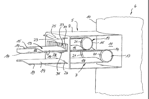
Figures 3 and 4 illustrate the construction and arrangement of a sandwich lock
5
on a vertical mill 6 with air flow conveying, only the area of the casing 10
of vertical
mill 6 being shown. The sandwich lock 5 is constructed in box-like manner and
has
a casing 8 with a front side 28, which is provided with a passage opening 23
for the
double strap belt 13 with the material 4 enclosed therein and which is in
particular
terminated in air-tight manner (see Figure 4). An end region 7 of the double
strap
conveyor 3 is located within the casing 5 and is consequently incorporated
into the
pressure system of the sandwich lock 5 and the vertical mill 6 by means of the
feed
opening 11. In order to avoid secondary air entry or exit, the double strap
belt 13
with the material received therein and the sandwich lock 5 are sealed, the
sandwich
lock 5 shown in Figure 3 is without a front side wall in order to illustrate
the
construction of the end region 7 and the deflection of the double strap belt
13.
The double strap belt 13 has a lower strap belt 14 and an upper strap belt 15.
For
the construction of a reception area 20 for the material 4 (Figure 4), the
lower belt
14 and the upper belt 15 are constructed in a trough-shaped manner and in the
vicinity of the marginal, material-free overlap areas 19, are superimposed in
mirror
symmetrical manner, so that a cross-sectionally biconvex reception space 20 is
formed (see Figure 4). Through suitable sealing devices, which are
appropriately
positioned upstream of the sandwich lock 5 and which are not shown, the double
strap belt 13 is preferably sealed several times, so that on the material side
a
secondary air introduction into the sandwich lock 5 and vertical mill 6 can be
largely
excluded.
9
CA 02445424 2004-06-02
The end region 7 of the double strap conveyor 3 received within the sandwich
lock
has a lower deflection drum 17, which is positioned relatively close to the
feed
opening 11. An upper deflection drum 18 for the upper strap belt 15 is
positioned
in a displaced manner, so that the material (not shown) resting on the lower,
further
5 extending strap belt 14 reaches an ejection point formed by the deflection
drum 17
and, as a function of the speed of the double strap belt 13 and the spacing
from the
feed opening 11, can be ejected virtually centrally into the vertical mill 6.
The deflection drums 17, 18 are constructed in a complementary manner to the
trough-shaped strap belts 14, 15 resting on one another in a mirror
symmetrical
manner. Corresponding to the virtually planar, material-free overlap areas 19,
the
deflection drums 17, 18 are provided with circular cylindrical front areas 21,
whilst
between the circular cylindrical front areas 21 and in a complementary manner
to
the trough-shaped strap belts 14, 15, the deflection drums 17, 18 are
virtually
constructed as a one-sheet hyperboloid.
In order to ensure the necessary sealing of the sandwich lock 5 relative to
the
atmospheric pressure, seals are provided in the vicinity of the front passage
opening 23 and a lower slot opening 24 for the deflected, lower strap belt 14,
as
well as in the vicinity of an upper slot opening 25 for the deflected, upper
strap belt
15, Figure 3 shows only an upper sealing area 34 of a seal 33 for the passage
opening 23 and a lower sealing area 35. The upper sealing area 35 has
vertically
adjustable sealing laminas, which rest in a resilient or sliding manner on the
upper
strap belt 15. The lower sealing area 35 of seal 33 is only partly shown. The
seals
of the lower slot opening 24 and upper slot opening 25 are not shown. These
seals
and the lower sealing area 35 can in particular be constructed as a labyrinth
packing.
CA 02445424 2004-06-02
Figure 4 shows the construction and arrangement of the double strap belt 13
between the upper, deflected strap belt 15 and the lower, deflected strap belt
14.
For supporting the trough-shaped area of the deflected, lower strap belt 14
backing
rolls 26 are provided. The upper, deflected strap belt 15 in principle
requires no
deflection drums. The double strap belt 13 between the deflected, lower and
upper
strap belts 14, 15 has the milling material 4 to be supplied in the cross-
sectionally
biconvex reception area 20.
11