Note: Descriptions are shown in the official language in which they were submitted.
CA 02445466 2003-10-17
Field of the ~~ve~ti~~
[~~i~l~ 'I'he present invention relates to a strut that can be locl~eci by an
eternal power source
to assist in termination of further n2otion of the strut, particularly nor
usE, in a door.
I~ese~°lpt,io~ of eya~:ed ~1r°t
[~~~~ Motor vehicle liftgates act to bona pro~~id~; access and. close c~~d
seal the rear cargo
area of a rnoior vehicle. 'pypicaliy, t&~ae, lift,~ate is pi~,Totally
moun.~.ed in a frame at the rear of the
vehicle and pivots about a hinge defrir~g a horizontal axis. 'the .',iftgate
rotates between a closed
position securedly resting within the frame ar4d an open position, wherein the
liftgate is pivoted
away from the frarrae to allodv access to the cargo area. 'f'he liftgate is
often nary heavy and roust
be moved against gravity to reach are open position. access to the cargo area.
is difficult and
dangerous when a user is re~uire:i to lift thyv liftgate to the open position
unassisted, ar~.d then
hold the liftgate in position while accessing the cargo area.
i~ [~1~~~~ lost modern vehicles use gas or spri:~g-Loaded cyliru~~.rical
struts to assist the user
while opening the liftgate, arid th°,r~ to hold the liftg~ate in an
open position. ~'ypical'1y, the ~rser
manually provides the initial force necessaary to partially open the liftgate.
'f'he strut then
provides a spring force and a rno~aent arm sa~~'ficierat to overcorn.e thp
weight oa the liftgate aid
move tl~e liftgate to a fully opened position. ~'he spring force and the
E~nor:~ent ar~ra of die strut
2~ then act to hold the liftgate in the os~en position while the ~cser
accesses the cargo area. "f'o return
the liftgate to a closed position, tl~e user mast typically thrust dowFivdard
orl the liftgate, appiyir~g
a force sufficient to overcorr~e tl~e upward forces e;~erted 6y the strut.
Typically a liftgate
assembly includes two struts at opposite ends of he frar~~ze. one end wf each
stru'~ i;~ pivotally
mounted to the liftgate, while the orWher ~.ncl o:~ each strut is pivotally
mounted to either the frame
2~ or the motor vehicle.
[000] Powered systems for auoxnatica'Ey moving vehicle iiftgates between an
open and a
closed position are also known in the art. 'f"ypically in such systerr~s, a
power actuator applies a
force directly to the liftgate. for e~arnple, F~.~. Patent loo. 5,5:~~,49~ to
I~owall discloses a
typical liftgate ope~aing systerr~ wherein t~ a struts are actuated by a pair
of cables wound around a
CA 02445466 2003-10-17
spool by an electric motor, replacing the user-supplied force nece:~s~ry to
initiate moverrnent of
the liftgate. ~~o~vever, a significant az~o~r~t of poorer is re~~.ired to
operate such a system,
resulting ~r~ a mechanism that is usna~ly quite large a~~d uses a
sig8~ificar~t amount of vehicle
space.
[0005 mother example of a pov~ered liftgate system is illustrated in ~T. ~'.
Patent loo.
~,3~?,g6~. to Rogers, fir. et al. This system provides a rod in addition to
the struts. ~'he rod is
pivotally motanted to a follower rn.ou=~ted ors a fixed linear channel. ~.
flexible dri~re loop moves
the follower to drive the tiftgate betv.%ecn open ?nd cyose~. positicsns.
~i°~ce the liftgate is directly
connected to the drive, some forrc of clurc~ or disengagcrrmnt mechanism is
re~s~ired to alloy
manual operation of the liftgate. 'peals ~isengagemer t mechaniszr~ further
consumes vel-~icle space
vahile also increasing costs.
[1~0a6~ ~.~. Patent IVTo. 5,f2~,t~~°:~ to Lin ct al. provides yet
another example o~' a po~re~°ed
liftgate system. A magnet is pro~~ldcd on a piston to bctter retain the piston
in a fL~lly extended
position. The force exerted by the n3agnet acts vrith the fo~°ce
g~;r~erated by the stmt to increase
a5 the force required to initiate co~~npression ~:of tl~e strut when rr-
~o~Ting the door out of an open
position. Por example, ~rith the str~a f~aliy extended, a forge bet~:~me,n
~0(~ 1~ a.t a strait
temperature of -40°~ and 8001' at a strut te~~pes atu~-e of
~~~5°~.' is required to initiate collapse of
the stmt with the magnetic force disabled. h;.,r~ the magnet is engaged, a
considerab=ly higher
initial force is required to overcome the ~r~agneti~, force. after tl"is
initial force is applied and the
magnetic force is overcome, the start coll~.pses raor~~~ally. The
s~isadvantage with this type of
system is that tlae separation of tl~e magnet nay require ~ rising force
follov~ed by a sadder
release, causing the liftgate to l~t:~r:h at the point of ~vlease.
[~~~7~ Control systems for powered liftgate sy:~te~ns ~~re also l~no~vn in the
art. ~~ch control
systems usually include an o'hstacle detcctior~~ component to stop tic~
liftgate ~v:~ile opening or
25 closing if an obstacle is encountered. Typically the; control system
xneasnres the force applied by
the liftgate or the actuator motor, or the, rate pat vvitich the ~notoo a
~r~o~~ing. The liffigate is
stopped if anomalies are detected in the measu~-mnents tending to indicate
that an ~abstacle has
been ea~coa~ntered.
[O~a~~ Finally, a large engagement force is necessary to activate most prior
art locking struts,
3~ ewhich atypically include a driver outside or tl~e strut housing. ~n this
t~fpe of syste~a, ~ rod ~n~ast
travel down the center of a pisto~d rod to tra:~slate the sig~~al fro~~~ the
drive~° to a valve. A
2
CA 02445466 2003-10-17
signi.fica~~t pressure differential exists between the oa~tside ~tinospheric
pressure where the driver
is located and the pressure within ~l°~e housing. 'p o resist this
pressure differential, tle driver aa~ust
exert a significant engageer~t force ~;o activate the valve. 'hherefore, it is
desirable to provide a
system v~~l~erein the driver is housed ~witx~in the lousing, thereby reduclrg
or elir~zinating the
pressure differential and reduiring rn~:cl: lower engagement forces.
~OaQ~] It is desirable to provide, ra. ~ locl~irg strut or stri.~ts to
srr~ootl~ly open and close the
liftgate and locp~ the strut in a fully extended positions without adding
unnecessary bilk or cost to
the vel°~icle.
~Q01~ ~dditionaily, it is desirable to prorride a driver located ~~itl~in a
strut housing to
l~ significantly decrease the pressure. dlffereni-ial betweea~ the drive- arid
a valve.. 'fle st~°ut is
connected to a control systen-~ to fro vide for control of the strut duri~-~g
~~overr~ent D:etween open
and closed positions.
S~.T~~~~~.~1~~'~ ~ ~ a~~: Il~~'V:El~TIi~
~a61~~ ~cc:ordingly, the present irrver;tion provides a lockiry strut
including a housing with a
piston rod e~tea~dir~g tlerethrough. a baffle rr~ounts on the piston rod to
divide tle lousing into
two chambers. An or~~fice through the bafl~e allows fluid to pass. between the
chambers to damp
reciprocating movenaen~:. ~,r~ electrorr4agnetic da-ive~- ~,vithin the housing
is selectively energized
to attract or repel a ferromagnetic plate to move the piste between a~~ open
position, t~rith fluid
flowing freely between the clarrzbers, ~nc~ a closed position, wherein tle
orific,°. is blocked to
prevent r~uid flow between the charribers and lock the strut in position. I-~.
plurality of orifices
away be spaced about the baffle, ~~rith tine number arid size of the ori(~ices
determinlr3g the
dampi~~g capability of the strut. t~ plurality of critters t~~zay be disposed
within the Dousing to
overcorrze fluid forces during rnove~~er~t of the str~ft betrveer~ are
e~terded arid a retracted
position.
2~ ~0012~y placing the driver ir;side tie .arousing, much of tie bulk and cost
of typical locking
strut systerr~s is eliminated. Addit;onall3~, locating the driver ~ritli~s tie
Dousing decreases the
pressure differential between the: rlr~~ver and the va.l ve, greatly
red3acir~g the force needed to
engage the locl~ing meclanisrn. ~° control system connected to tie
driver selectively energizes
the driver far greater control over tie systeZduring movernerlt. ~~ plurality
of drivers can be
3C used to provide even greater control over tie selective locking f~xr~ctiot~
of the strut.
3
CA 02445466 2003-10-17
[~l~~ Ad~r~nt~gcs of the present invcn~.~o~a will be readily appreciated as
the s~~r~e bccorncs
better understood by reference to t~~c ~olio~n~g detailed de;9cr~pti~~n when
considered in
connection with tlm ~ccozrnp~n~ing d~°awings ~rhcrcina
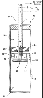
~ [~~~~~ ~ig~rc 1 is a cross-scctor=,~~i ~ric~>~~ of ~ frs~~ en~abodimer~t o~f
~ i~ci<ing strut ~ccordi~sg
to the present yn~lcntion shoring tic strait in an unlocked condititan5
~~hcrcis~ ~ pivrality of
oriaficcs ~.rc aznblocked to ~iiou~ fluff d .~io~~ between t~~ro ci~~~nbers of
a housing
[~~~,5~ ~ig~rc 2 is ~ cross-sectional ~ic~u of the l~~cking strut of ~igcrc ~
in. ~ locked
condition9 wherein the, orifices are bi~~cl~cd 6y ~ platc9 prc~~er~ting ''lid
flow bctmec~ the
i~ chaanbers and locking the locking s'°~~-~t;
[~9t~~~~ Figure 3 is a cross-sectional ~ric~:pi o~ a second e~~~bodir~cnt o:~
the locking :;trot
showing the strut in the ~anlocl~ed ~;ondition:,
[~~~'7~ figure ~ is a cross-sectional ~icm of tl~c loc,~~g strut of ~igurc ~
in tt~c locked
cor~dition9
15 [~fll~ ~igurc 5 is a cross-sectional ~ie~~r of ~. third ernbodir~~~nt of
the 1~cking stmt slaoming
the strut i~~ the urilockcd condition
[~~~~~ :i~igure 6 is a cross-sectional ~icw of tl~c locking strut ,of ~-~igu~-
e ~ in tl-~e locked
conditaor~;
[~~~~~ ~igurc 7 is ~. cross-sectional ~icw off.' a f ~uith en,bodi~ent of the
locking strut
2~ shov~ri:~g the strut ia~ the unlocked condition;
[~~~~] 1~igure ~ is a cross-scction~~i ~rie~r of the locking stmt ~~f iyigure
'7 in tl~e locked
conditiony
[~a~Z~ ~igurc 9 is a cross-secton~l ~ie~r of a fifth cbodi~ent of tf~e locking
strut slowing
the stmt in the ~zz~locl~ed conditic~ny
2~ [~3~~~~ Figure 1d is a cross-sectio~~al ~ie~.v of the ioclcing stmt ~~f
higurc 9 i$~ the locked
condlt~~n~
[~~24~ ~igurc 1 P is a cross-sectional ~ic~.~r of a sixth e=nbodin~cnt of the
locking strut
showing tl~e s:r~~t in the unlocked cor~~lition9
[0~2~~ 1~igure 12 is a cross-scctio~~al ~.~icw of tl-~c ~ocl<ing strut:
o~"1~igurc i:i in the locked
30 conditions and
CA 02445466 2003-10-17
~~~~6~ p'igure i~ is a pcrspect~~~, °aiew of a rear p:c~rti~r~. of a
typical vehicle incorporating a
locking strut of the present i~wcr~ti~r~.
[~~~'~~ ~efcrring to Figures 1 9:hr~ugr~ 1'~, ihcre is illustrated ,~
loclcirrg strut IO of the present
S ir~z~erDtis~r~. ~'he strut la comprises a ~~c~lic~w hc-asi~~g l2 hcretica~ly
sca.lcd vaiih ~r~ ~pcr~i~g 1I at
c~~e e~~d. 'The housing 12 is preferably a cylindf°r. A, piston rod f~
e~ctcr~ds through the opening
t in a sealed fit. 'The piss~t~ rod l~ r~e~res with respect to the he>~.:~sing
i~ between an extended
positian and a retracted positions ~~ haffle t ~ ~r~~unts t~ the pistu~~ rod t
4 within the housing l2
separating the h~usir~g l2 ini~ are a~ppcr cha~~ber l~ and ~ lower chamber 2~.
'The baffle 1~
Id slidingly engages the ulterior walls ~~ the hc~uslng l~ to slick al~r~g the
housing i2 as the piston
rod l.~ r~~o~res bet~veca~ the extcrrded ~znd retracted p~sitions. !~i laser
one orifac~e 2~ e;~t~.,a~ds
through the baffle l6 defining fluid passageways through the baffle t ~ to
allow Eland to pass
between the chambers i~, 2~. '~Jhi~c the fl}~:~id is preCerab-$y air, other
fguids, for couple oil, rn:ay
be used without changing ihc inverrti ~m concept. ~~dditionally, ~%i~ile r~hc:
e~~bodi~ents shoar~r~ in
i5 ~igwres t through 1~ illustrate two orifices ~~, army number of ori~iccs 2~
may be used, with the
total nurr~ber and size of orifices 2~ deterrair~ing the ~~nount of da~pir~g
provided by the strut l~.
~~d~~~ l~ deer ~~;- mounts wiilrirf tl~c housing 1 ~. 'f'hc dri~e~r 2~
co~~prises art
clearomagnetic coil energizablc to produce arr ele,cir,~magraetic driver
force. electrical leads ~~
extend from a power source through ~lae piston rod l~9 conr~cctin~ to the
driver 24 to selectively
2~ provide power to energize the drawer ~.~ in rcsporEse to external
cc;~?tr~ol sggr~als. for example, .~
control slrsver~ could measure a force orr the locki~~g strut Il~ du~-iy~g
ro~~er~eni frog a°~n onen
position to a closed position and energize the driver ~;'I upon the detection
of an excessive force,
perhaps indicati~~g i'ne presence of an obstacle. 'f'hc driver .~~- rnay also
be energized tire response
to a program setluerlce or ~ position control detection system's.
2~ ~~~2~~ hrcferably, the driver ~~ iv errcrgized according ro a pulse width
modulation signal,
wherein current is rapidly cycled through the leads 2~S from the pc~~~er
source to the driver 2~s-,
thereby pa~oducir~g a partial duty cycle,. pulse ~,vidth rn~dulatior-~ is
preferred over a constant
supply of power because ii provides r~iore coni:rol of ~:he dri vcr 2~1,
espcc;ially when pr°essure is
high. increased control over the db°i cr 2~ is particzrlav-ly
irrtpor'car~t to prevcr~t the locking strut
Vii; i_~ from ac.ce's_cratrng more rapidly i~an des~-ed. ~ or ~~xar~ple,
wht,r~ il~p loclci~g stmt 1~~ is ~,~scd
CA 02445466 2003-10-17
in a door, it is necessary% for the door mo cl~se at a~~ apl'ropriate speed.
~s tree pist~~~ ~:s~d f 4
travels ~r~a~ an extended position to a retracted position, arid tht~.~ the
door travels ~r~an open
position to a closed positi~~, pulse width rrz~dt~lati~~ effects a
sl~~~e~° charge l~et~aee~~ the two
positions, providing rrlore c~ntrol ~~a.~~i~ig mo~d~~e~t.
~'~rr~ir~g r~~~ra to the first e:~x~t~~dimr~~t illustrated in Figs~res f and
2, the piston rod i4
ir~ch~des an opening 2~ for recei°;~i~~g a ~e~~~:~rag~~e,tic plate 30.
~l~re i~ez-r,~r~ag~etic piste 30 is
disposed within the h~using i2 ~~~° r~~trerr~e~t iset~~e~;v.~ an open
p~c~sitis~~ space fr~r°.~ ~i~e hackle 16
~~r alI~'ving r'~~aid to pass through the ~ri~iees 22 a~~. a closed pc~;~iti~n
c~avering the orifices 22 t~
prevent flog of l~uid between the chambers Lg, 20. ~i'he Iet~r~~agnetic date
30 co~r~p~ses an
IO annular Mange 32 and a stem 34, ~rith the ste.~~~ 3~ extending through the
bax~te f ~ a~~f~ sitting
within the: opening 2~ in the pstor~ ~:o~J _~r. ~l'~~~; flange 32 comprises a
ferrorr~agneiic material
such that it is attracted or repelled by an electromagnetic force. ~: valve
spring 36 disposed
with::n the opening 2~ exerts a spri~~g force or~t the step 3~- of the
rver~.orr~agrcetic piste 30. ~7i~en
the flange 32 is spaced from the baftie g~, the ~.ocl~ing str~.t I0 is ia: ~r~
unbioci~ed condition,
~ thereby t~~id cap freer pass bet~ree~ the chambers f ~, 20 trough the
orifices 2~ al'to~ring the
piston rod I4 to move between the extender'. aid retracted positions. In a
locked condition, the
flange 32 engages the 'raffle I6 to coyer the orifices 22, preventing .~9uid
floe between the
chambers I~, 20, and locking the piston rod i~ i~ p3ace.
~~~~1~ each err~bodiz~aent of the present ir~ventior~ rraa~,~ be operated
fr~gn tl~e ope:~ p~sition to
20 the closed p~sition, o~ from the dosed position to the open positio:~. I~~
a first c~nfiguratior~~ of
each em~~odarnent, the valve spring 3~ is in a resting state, r~~eaniiog the
Fralve spring 3 ~ is neither
compressed nor expanded, when the aer~~ozr~agr~etic pi4ate 30 is in tire op~;n
position as shown in
Figures I, 3, :~, ~, 9 and. I I. ~r~ergi~e~tion of the driver 2~ naves the
ferromagnetic plate 30 to
the closed position shown in I~igures 2, ~'., ~, 3, 10 and i2. ~e-energising
the driver 2~ returns
25 the ferromagnetic plate 30 to tree ope~~ p~sitior~. Ire a second
configuration, the valve spring 3~ is
in the resting state when the fer~on~agnetic, plate 3~:~ is in the close:
position, and energi;~ati~ra of
the dri~re~~ 2~- moves the ferrornagneti~; plate 3-~ to thge open positions.
_In This config3a~Patior~, de-
energizing the driver 2~ ret~zrras tl~e ferromagnetic pla:~e 30 to the closed
position.
[~~~:~~ Returning now to the first e!~bodi~~7er~t shown irE ~igu~-es f a~~d 2,
the driver 2~
30 preferably rr~ounts on the piston rod I~ above tk~e baf~23e Iea and tine
ferromagnetic plate 30 is
positioned beI~~~ the baffle I~. In a virst configuration, ene;rgi~i~g the
driver 2~ r~agr~eticall~
CA 02445466 2003-10-17
attracts the flange 32 of tl2e ferro~nag~~etic plat: 31?. 'the
el~:ctron~agnetic force eace~e:d by the
energized driver 24 overcorr~es the sp~°ing force exerted by the valve
spring 3~ and the, stern 34
moves upward, corrapressing the val~-~v spring ~~ vritl~tin the opening 28 r~
the piston rod ~4. The
flange 32, being attached to the stern ~4, lilee5~rise moves upvaard to engage
the baffle ~6, closing
off tlhe orifices 22 to prevent farther il~.id flow between the charribers 1~,
2a and tl-~tas, prevent
movement of the piston rod 14. ~~l~hen the dri~~~er '~4 is de-energized, the
vazve spring 36 urges
the ferromagnetic plate 30 back do~.v~~~vard, t?~6:reby unblocking the
orif':ces 22 to res~~rr~e fluid
flour between chambers s8, 2~ and n~rr~ml operation of the, locl<ir~g str~~
i(~. In a second
configaaratior~, energizing the driver :~4 repels the viange 32,, exp~rnding
the valve spring 36 to
f ~ disengage the flange 32 and the b~.ff~: l~ to urihlock 1:he orifices 22.
"~~Cen the driver is de-
energized, the valve spring 3~ urges she ste~°n 34 back into the
opening r8, re=bloclcir~g the
orifices 22.
~~33] figures ~ and 4 illustrate ~~he locked a.nd ~.nloclted co~~di~ions,
respectively, of a
second embodiment of the locking swat ~ ~ of °ihe present invention.
)rn this errnodirncnt, the
IS ferrorr~agnetic plate 3~ comprises a z=~,rrornagr~etic :Mange 32, a ste.n:
34, arid a val~re ;i4. 'I'he
driver 24 is preferably rr~ounted ors a guide time 38 extending between the
driver 24 g~nd ache
baffle l~. The guide tube 38 prefeg°ably recounts to the baffle l~
surrounding the orifiices 22
through the baffle ICS such that ft~id ~~ows thx~~;ug~~~ the orif5ces 22 into
the guide tube 38. ~ he
guide tube 38 includes a passage 4~ i~or allovving f~uid to flow into rl~e
lover chamber 2(R. The
2~ passage 40 rnay comprise a hole ti~are3ugh or a slit around the guide tube
38. ~,dditior~ally, a
plurality of passages 40 may be used, with the number andl size c~f fee
passages 4~ dcterrnining
the ;mount of damping provided roy rube locking stroi: l~. ~ller~~atively.,
fhe guide t~~~~e 38 ~no~~nts
to the baffle 16 such that the orifices 22 lead directly into the lov~~er
chamber 20.
C~34~ T he stem 34 of the fern or4-qagnetic i~late 3t) extends throp.~gh the
driver 2.4 into the
25 guide tube 38. preferably, the valve 44 mounts to ogre end of the; stern
:~4 wvithin the guide tube
38, while the ferromagnetic flange 3:~ mounts to the opposite end of the stem
34 outside of the
guide tube 38. however, the ferromagnetit°, flange, 32 rnay also ~~e
seated within the ga~ide tube
38. As both the valve 44 and the ferromagnetc; f~an,ge 32 are rr~o~arEt~;d to
the sterr~~ 3~~, ~novernent
of the fe~~ro~nagnetic 1'lar.ge 32 causes n~ac~ err~cnt of v~,l~e valve 44.
The o~alve spring 36 comprises
3~ a guide spring 48 disposed within th,U guide t~,.~he 38 between the draper
24 and the valve 44, and
a plate spring 5~ disposed bet~vee~~ t_Fe drifter 24 anei the plate 3~.
C
CA 02445466 2003-10-17
[~35] In a first configuration of the second e~xabodirnent, energizing the
driver 2~~
magnetically attracts the ferromagnetic flange ~2, ceasing the fe~~~onzagnetic
flange 32 to move
upward tovrard the driver 24, thereb f compa~essing t~~e plate spring S~.
~lternatively~ if the
ferromagnetic flange 32 is locate w=thin the guide tube fig, energization of
the driver 2~ repels
the ferrornagrtetic flange 32, causing the ~er~°orr~agnetic flange ~2
to move upward array from the
driver 2~., expanding the plate spring SG. Ie/.ioven~ent of the ferromagnetic
flange 32 causes
movexraent of the att~.ched stem 3G, and therefore moves°nent of the
<~ralve ~.~., thereby expanding
the g~,zide spring 4g. The valve ~4 ej~gages tine baffle ~6, sealing the
orBfices 22 to prevent ~~ovv
of fluid between the chambers fig, 2, preventing further rnoverne°nt of
zhe piston rod. 1~.. ~s
l~ shown in Figure ~, the valve ~4 also seals tl~e passage ~~. I~owe~~er,
because engagerr;ent of tine
valve 4~- with the baffle ~~ preve~~ts quid l~l~w into tire guide tu~>e ~8,
sealing of the passage 4~ is
not necessary tc lock the locking strut f~. then the driver 2~ is de-
energized, the g~zide spacing
4.g and the plate spring 5C urge the valve ~~ a~~d the i°errosr~agnetic
piat~; 3~, and therefore the
shaft 42, back downward, thereby unblocking the baffle 4 ~ to res~~rs~e fluid
flow and normal
xS operation of the locking strut l~.
~1~~93~] In a seco~~d configuration, the gc~ide sl;ri~~g 4g and the plate
spring 5(i a~~e in the
resting slate when the locking stmt ~ is in t~.e lock~;~ condition ~ho~wr_ in
Figure 4. Energization
of the driver 2~ repels the ferrornag~ etic flange 32, ~:o~npressing the
g~side spring 4g and
expanding the plate spring S~ as s~~cwn in C'igure ~, ire-energiz~tioru of the
dri~~e~° 2~ urges the
2J springs fig, S~ bac3c to the restia~g st~~te9 reta~-r~ir~g the locking stmt
l~ t~, the locked condition.
~~a37] !~ third ernbodirraent of t he locking strut 10 is shown in Figures S
and ~. ~ retaining
plate S~ mounts to tl~e piston rod l~f, preferably in tie upper ch~~.~Aber ~1'
8 above the baffle ~~, for
engaging the ferromagnetic plate ~(' ~N'.~.en the locking shat 1C is in the
unlocked condition as
shown in Figure 5. The valve sprint 3v is disposed between the fe~~ornagnetic
plate ~J and the
25 baffle ~~. ~refera'ory, the ferromagnetic plate 5fl includes an an~~~alar
flange 23 enclosing tl"ae
valve spring 3~ and covering the orifices 22 vrhen tire loc:~;in.g stra.~r_ f~
is in the locked condition
as shown in Figure 6. 1=Iowever, another s:~ape of fcrromagr~etic plate ~0
rr~ay be used. The
driver 24 mounts to the piston rod l~~- within the. io~xmr cl~an~ber 26
beneath the baffle ~6. In a
first configuration, energizing the d=aver 2~f attracts the ferromagnetic
elate 30 into engagement
with the baffle i6 for sealing the s~rifices 22, and compresses the valve
spring 36. ~e-energizing
the driver 24. causes the valve spri~~~J 3~ ts~ urge the =~erroi~r~agnetic.
plat. ~~3 toward the retaining
g
CA 02445466 2003-10-17
piste Sl and away from the baffle =~. fn a second cCnfiguration, energizing
the driver 24 repels
the ferromagnetic plate 3(9 such that the ferromagnetic plate 3Q disengages
the baffle 1~ to
~nbiock the orifices and expands the valve spring 36. then the driver 24 is de-
energized, the
valve spring 36 returns to the resting state, Hnoving the locking st:ut 1~3
~acic to the locked
S condition:.
[~~3~~ Figures 7 and 8 show a fo~~ar'~~e~-nbodirr~e~t of tl~e present
iny~ention, wherein the
valve spring 36 is again disposed bet~vcen ~hc ferrornagnctic plate 3(~ and
the baffle l ~. '~'he
driver 24 i's preferably mounted in the upper charhber ~8 above t=3e
fc~onzagnetic plate 3~,
eliminating the need for the retaining plate 5 l . ~n a first
config~,ra~ation, energizing the driver 24
repels the fer~°onaagnetic plate 30, compressing the valve siring :~S
and anoving the f~rro~nagnetic
plate 3t9 frost the open position sho~,vn in Figure 7 to the closed position
shown in Fig~.re ~. ~n a
second configuration, energizing the driver 24 attracts the. ferroar~agnetic
plate 3t9, expanding ~:he
valve spring 3~ and moving the fe~~ornagnetic prate 3~ fro~~ the closed
position sho~~~~ in. Figure
~ to the open position shown it ~°igvre ?. ~c-en~:rgizing the dri~Jer
24 in each con~'i,guration
l S returns the ferromagnetic plate 3~ to the, initial position.
~a~39~ ~. fifth embodiment oa° the piesent invention is showa~ in
Figures ~ and ~0. ~n this
e~nbodirnent, the driver 24 preferably rrao~.nts to thc, piston rod 1.4 in the
upper chamber 1~ above
the ferromagnetic plate 319, with the; valve spring 3~ disposed b~et~leen the
driver 24 arid the
ferromagnetic plate 319. ~n a first configuration, energizing the driver %4
repels the ferromagnetic
2C plate 319, expanding the valve spring 3~ arid moving the ferrornagraetic
plate 3C~ to the closed
position shown in p'igure 10. In a second configuration, the driver 24
attracts the fcrrornagnetic
plate 3~, compressing the valve spring 3~ and moving tl-~e ferromagnetic plate
3~ to the open
position shovvv~ in Figure ~. l~s 4ui'.h previous ea~nbodimerats, de-
energization of the driver 24
returns the ferromagnetic plate 3Q to the i~ait~.al posation.
2S ~~~~0~ Fig~zres I1 and ~2 shop- a sixth embodirner~t of the present
invention, again including
a retair~~ing plate 5 f, ~,vith the valve spring 3~ disposed between the
fewo~~agnetic plate 3(9 and
the retaining plate 5i. '1'he driver '~:~- a~our~ts to the piston rod ~4 in
trae lower chamber 20. ~n a
first configuration, the valve spring 3tS sirs i~ the resting state when the
locking strut l~ is in the
unlocked condition shovrn in Figure 1 l.. :energizing the driver 24 attracts
the ferrorr~agnetic plate
30! 3(9, expanding the valve spring 3~ and rr~oving the ferromagnetic plate
319 to the cia~sed position
shown ire p'ig~.re 1.2. conversely, ~n a second configuration, the, valve
spring 36 si~a in the resting
CA 02445466 2003-10-17
state when the locking strut ~d is iy~ the loclc~,d condition. ~~nergi.~;inb
the driver 24 repels the
ferroagneiic plate 3~, corr~pressir~g the vale spr~r~g 36 and ~no~~ia~g the
ferromagnetic plate 30
to the open position as shown in Figure l 1. lie-energizing the dri~rer 24
returns the
ferromagnetic piste 3~ to tl°~e opposite positions.
~~~41i~ Deferring now to Figure, 13, t~.e iocicing strut IJ is
sI°~owr~~ as eased i,z a reaa- liftgate 56
of a z~notor vehicle 5~, one of many po~~e_ntiai uses cf ~:iae pr~;sent
invention. ~':~en the Iiftgate 56
is in a closed position, the liftgate 5~i securedly rests adjacent a frame 54,
with the liftgate 56
biased toward tl:e closed positiors due to its ;weight. A hinge asse~~i~iy 5g
prodding a generally
horizontal hinge axis connects the iiftgaa~e 5~~ as~d the frame 54. 7C'h~:,
liftgate 5t~ rotates ~:apward
$~ about the hinge axis to an open position away from the frame 54. similarly,
the Iiftgate 56
rotates downward about the hinge axis to return to the closed position.
~004~j A latch assembly 60 mounts on the liftgate 56 for relmasably locking
the liftgate 56 to
the frame 54. A. corresponding striE~er 62 mo~~~ats on the frame S~I~. ~'he
latch asserrabiy 6(I is
preferably a power assisted latch assemi~ly as lmown in the ard. lr~ such an
assembly ~C9, the latch
I5 assembly 60 pulls the liftgate 56 fully into tree closed position as the
liftgate 56 nears the closed
position. A liftgate seal disposed on either !:he lif'tgate 56 or the frame 54
seals the Iiftgate 56 to
the frame 54 where the Iiftgate 56 is in the Closed position. Additionally,
the latch assembly 6~
~utornaticaliy releases as the liftgats; 5t~ 3noves from ~:he closed position
to the open ,p ositiorg.
Alternatively, the striker 62 may be power assisted to perforrr~ the same
functions as the, latch
2~ assembly 6i?, eliminating the need to supply p~wer to the latch assembly G.
[004~~ 'f'he vehicle 52 includes a locking strut 1Q of the presexrt invention
pivotally mounted
between the frame 54 and the Iiftg~te 5~. Preferably; a second strut i~ is
similarly rnoa,~nted on
the other side of the frame 54 and Iiftgate 56, which may or may nct be of the
type contemplated
by tie present invention. A control system 64 disposed within the ~el-~icle
controls the locking
~,5 strut ~~. ~'o open the door from tl~e closed pbsition, .;.he latch
assembly 6~ or the strihe~r 62
disengages the lock. ~f an anomaly is detected by the control syst:e64 while
the Iiftgate 5~
proceeds frorr~ the closed lsosition to the open position, and thus the
locking strut lad proceeds
from an extended position to a retracted position as described below, the
control system 64
activates the dri~rer 2,4 to cease motion of the loclcizdb strut i0.
Pr~,fer~~bly this is achi4ved using
3~ pulse wave rr~odulation~. ~pecificapsy, motion of the ~ocl;i~~g strut 1~ is
not instantly halted during
movement of the liftgate 56, which could break the Iocl~ir~g strut l ~ d~ae to
internal pressure and
I I~
CA 02445466 2003-10-17
load on the locking strut I~. Instead, socking of the locking stmt l p by
blocking the orifices 22
occurs through pulse wave modulation, effecting ~ slower change between
rraovement of the
locking strut i~ and stoppage of movement.
~00~4~ then the locking strut l 1l is in the fully a xtended position, the
baffle I& rests near the
top of the housing I~, thereby creating a~~ upper cha3r~ber 1.g which is
signil°icantly s~rdafaer tlsan
the lower chanibcr 2G, with the pist~.br~ rod I4 e.~tcvdi~~g al~~aost fv'3ly
~ateida of the ~gousing y2.
t~s the locking strut 1~ moves from a=~ extended posltior~ try a retracted
position, the b~ffje I~
slides along the housing I2 to reach tl5e fully rctr~ct,.d position, ~~-
~herciv tl~e baffle i ~ rests near
the bottom of the housing I2 aa~d tl°~e ~appev chamber I ~ is
signirix.:antly larger than: she lower
Il~ chamber ~~. Fluid passage through the orifices ~2 i-r~ the baffle fi ~
°ffects movement between
the two positions. her the lockizzg strut t1 .rrzoves from an axt:cnded
position to a retracted
position; fluid Pushes through the orifices ~2 from the upper eharnher I~ to
the lover chamber
2~, creating ~. fluid pressure cxer°~ing a do'RFn~avard fluid force on
the assembly. Co~~vcrscly,
rr~oving the locking strut I Q from a ~vtract~;d posueion to ata extended
positioa~~ creates an upward
I~ fluid force ore the assembly as fluid moves through <~he orifices ~,~ from
the lower Ch.a~~a~oer 20 to
the upper chamber I~. '~'hese fluid iorccs will have an impact o~,~ the
cfficie~cy of the assembly.
For example, referring to Figure= I az~d ~, tl~~, dow~~ward :fluid force
during rnovebment fron~a the
c~ctended position to the retracted position tends to force the ferromagnetic
flange ~:~ away from
the baffle I~. ~'herefore, lochi~tg of the locking strait IO in the li~-st
configuration, for example,
2~ requires a dr~lver force large enoagl~ to ovcrcorr~;, both the r'luid f
once and the spring force biasing
the ferromagnetic flange 32 io the open position. Conversely, the upward fluid
force during
a~aovement from the retracted positi=Jn to tl~e extended position t~:;nds to
force the l°epromagnetic
flange ~2 toward the baffle I6. 'l"hcrcfore, to keep il'c locking strut lfl in
the unlocked condition,
for example in: the second conligaratior~, reqn:ires a drsvc~° force
large enough to ovesrcome both
2,5 the fluid force and the, spring force Biasing the ~_'erro~raagnetic
fla_~:ge 32 to the closed position.
~'hese tendencies r~.ust be cozlside,red when chocsir~g which errnhodiment of
the present invention
to utilize in a particular applicatioa~. ~dditioa~ally, a locl~ing str~.~t I~
~aay employ t~,vo drivers ~4
to rnorc easily resist the opposing forces. In the first configuration of the
first ernbodirraent,
rraounting a driver 24 in the lower cha~bc~- ~d for repelling the
ferrorr=agnctic r"lartge ~2 du~°ing
3l3 movement of the locking strut Its frt-orn the extended to the retracted
position would i~nprovc
performance of the locking strut 1.~. hhe sed~ond d::river could also attract
the fcrrornagnetic
II
CA 02445466 2003-10-17
flange 3~ to lceethe locking strut i~ car~locl~e~~ daring n~aoverr~erit frc~rr
the retracted to the
extended position in the second cc~nfigaratic~n.
~~f~~5] 'while the invention is described her ei~~ for use in a rnc~tor
vehicle liftgate assembly,
the strut may be ased in many applications ~~~l~ere damping is desirable,
including a motor
vehicle shock absorber or accessory drive tensioner, or any door ~aili~ing a
strut, fox example, a
garage door or an industrial door.
~f10~~6] The invention has beea~ described in are allustrative manner. It is
to be understood that
the terminology which has been used rs ir~ten~ied =o be in the nato~~e of
rwvords of description
~°atr~er t~~an of li~itat~.on. Tn fact, many ritoclificati~ns and
~~ari~tic,ns ~f t'~e ir~.vention are possible
1C~ in light of the above teachings. T'F~e.refore, vNithin the scope of the
apper~cled claims, ~~he
invention Bnay be practiced other than as specis'ically enumerated within the
description.
1~