Note: Descriptions are shown in the official language in which they were submitted.
CA 02445780 2003-10-29
WO 02/095476 PCT/GB02/02373
ROTARY STAGE FOR IMAGING A SPECIMEN
Field of the Invention
This invention concerns a rotary stage for imaging a specimen, and a method of
obtaining
an image of a specimen. The invention is particularly, but not exclusively,
concerned with
optical projection tomography and three dimensional microscopy.
Background of the Invention
Optical imaging apparatus for producing three-dimensional images of samples by
optical
projection tomography is known, see for example US Patent No. 5,680,484. The
optical
apparatus disclosed in this prior art patent takes a series of digital images
of a sample from
different angles. These images are fed into an algorithm which use a
mathematical
transform to reconstruct a three dimensional image. In US 5,680,484 the
specimen is held
within a transparent tube which is supported at two points so as to be
substantially
horizontal, and the tube is rotated using a stepper motor and driving belt to
allow different
parts of the specimen to be imaged. Light refraction from the tube affects
signal quality
and use of the tube places a severe constraint on the maximum size of specimen
which can
be imaged. The apparatus disclosed in this prior art patent has several
limitations which
affect the potential uses of this imaging technique, in particular it is
difficult to introduce
the sample into the hollow cylindrical tube, and difficult to adjust the
position of the
sample.
It is an aim of the present invention to provide an apparatus and method which
overcome
at least some of the aforementioned problems.
SUBSTITUTE SHEET (RULE 26)
CA 02445780 2003-10-29
WO 02/095476 PCT/GB02/02373
2
Summary of the Invention
In accordance with one aspect of the present invention, there is provided a
rotary stage fox
use in imaging a specimen from a plurality of directions, the rotary stage
comprising
specimen support means including a rotatable member operative to rotate a
specimen to be
imaged about a vertical or substantially vertical axis of rotation transverse
to an optical
axis along which light is emitted from the specimen, wherein the specimen
support means
is disposed above a stationary imaging chamber for receiving the specimen
immersed in
optical imaging fluid within the chamber.
The rotary stage may be - used with a separate microscope and associated
hardware and
software that allows three dimensional imaging of a specimen, such as a
biological tissue.
By having a specimen support means spaced from the microscope, the positioning
of the
specimen cart be easily adjusted due to improved accessibility of the specimen
holder.
With an elongate specimen, the longest axis of the specimen is substantially
parallel to
gravity when held within the specimen support means. This allows the specimen
to be
held at one point only, again assisting with location of the specimen within
the specimen
support means, and avoids deflection of the specimen through gravitational
effects, as such
deflection can cause unwanted distortion of the specimen shape and affect the
accuracy and
resolution of the image obtained.
By having a stationary chamber separated from the rotational part of the
stage, the
chamber shape is not limited to a rotationally symmetric shape. Preferably the
chamber
has at least one planar face on which light impinges to image the specimen.
Use of a flat
planar face with no imperfections or undulations ensures that image
distortion. due to
refraction of light is reduced. The chamber may be formed as a transparent
hollow cuboid
and arranged such that two opposing sides of the cuboid are substantially
pero, endicular to
the optical axis along which light is emitted from the specimen so that a
large cross-
sectional area is presented to the optical axis. The selection of such a
chamber with a
square cross-section ensures that the amount of light refracted before passing
through the
specimen is substantially reduced over prior art cylindrical rotating chambers
and thus
CA 02445780 2003-10-29
WO 02/095476 PCT/GB02/02373
3
image quality is improved. One wall or face of the chamber may be shaped so as
to
refract light in a desired way, for example to provide a magnifying effect.
The rotary stage may further comprise a pivotally mounted adjustment means,
such as a
lever, having a spigot extending therefrom, the spigot being arranged in use
so as to
engage with a specimen to alter its position relative to the axis of rotation.
The rotary stage may further comprise a prism positioned so as to receive
light after the
latter has illuminated the specimen, the prism acting to deflect light through
90° to enable
the light to be received by a microscope with a vertical optical axis. By
using a prism, the
optical path to the microscope does not need to be straight, and thus
modification of
existing microscopes is not needed for use with a rotary stage in _ accordance
with the
present invention.
The rotatable member of the specimen support means may be carried on an
adjustable
platform, the position of which relative to the horizontal is variable. This
allows the axis
of rotation to be adjusted relative to an optical axis so that if required a
90° angle is set
between the optical axis and the axis of rotation. This is particularly useful
for three
dimensional imaging.
The adjustable platform is preferably vertically adjustable so as to raise and
lower the
rotating member relative to the optical axis, so allowing a specimen to be
lowered into or
out of an optical path of light.
Preferably the rotatable member is formed to enable the specimen to be hung,
suspended
or to downwardly depend from the lower end of the rotatable member. Where a
specimen
is appropriately prepared with a magnetisable metal mount, attachment of the
specimen to
the specimen support means is then straightforward, just relying on magnetic
attraction and
not on a delicate fixing. This is of advantage as typically the specimens are
rather small
and delicate, usually with a diameter in the range 1-20mm, and securing them
in a holder
using a screw thread can be complicated.
CA 02445780 2003-10-29
WO 02/095476 PCT/GB02/02373
4
In accordance with another aspect of the present invention, there is provided
a method of
obtaining an image of a specimen, the method comprising rotating the specimen
about a
vertical or substantially vertical axis of rotation transverse to an optical
axis along which
light is emitted from the specimen, wherein the rotating specimen is immersed
in fluid
within a stationary optical chamber.
Brief Description of the Drawings
The invention will now be described, by way of example, with reference to the
accompanying drawings in which:
Figure 1 is a perspective view of optical imaging apparatus comprising a
rotary
stage in accordance with the present invention together with a microscope;
Figure Z shows a schematic illustration of how such imaging apparatus is
controlled when acquiring digital images;
Figure 3 shows a front perspective view of the apparatus;
Figures 4(a) and 4(b) are schematic diagrams used to illustrate the most
appropriate working configuration of the apparatus;
Figures 5(a), 5(b), 5(c) and 5(d) illustrate attachment of a specimen to the
specimen support means and alignment of a region of interest;
Figures 6(a), 6(b) and 6(c) are schematic diagrams used to explain resolution
of
the apparatus;
CA 02445780 2003-10-29
WO 02/095476 PCT/GB02/02373
S
Figures 7(a) shows a cross-section through a prior art specimen containing
tube,
with Figures 7(b) and 7(c) showing two specimen. chambers as used in the
present
invention;
Figures 8(a) and 8(b) show a partial plan view along line VIII-VIII of Figure
1,
illustrating use of a pivotally mounted lever to adjust specimen position;
Figure 9 is a perspective view of modified optical imaging apparatus according
to
the invention,
Figure 10 is a diagram illustrating the apparatus of Figure 9,
Figures 11a, 11b, 11c, 12a, 12b, 13a, 13b and 14 illustrate positioning and
viewing of the specimen image in the apparatus of Figure 9,
Figures 15 and 16 illustrate a collimated illumination means which may be used
in
the apparatus of Figure 1 or Figure 9,
Figure 17 indicates a way of selecting wavelength from a light source in the
optical
stage of Figure 1 or Figure 9, and
Figure 18 illustrates a modification of the apparatus shown in Figure 16.
Detaiped Description
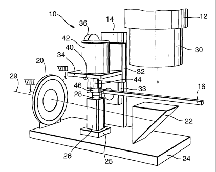
Figure 1 shows optical imaging apparatus in the form of an OPT scanner
comprising a
rotary stage 10 and a long working-distance or dissecting microscope 12,
separate from the
rotary stage 10. The rotary stage 10 has a support 14, a pivotally mounted
lever 16, an
iris and optical diffuser 20, and a quartz prism 22. The support 14, iris and
diffuser 20,
and prism 22 are fixed to a base 24 of the stage 10, as is a holder 25 for
receiving a
CA 02445780 2003-10-29
WO 02/095476 PCT/GB02/02373
6
transparent chamber 26, or cuvette, of a generally cuboid shape. The cuvette
26 contains a
fluid with suitable optical properties for imaging a spECimen 28 suspended
within the
cuvette, an appropriate fluid being a mixture of benzyl alcohol and benzyl
benzoate. This
apparatus can be used for brightfield, darkfield and fluorescence imaging but
is., particularly
appropriate where a three dimensional (3D) image of the specimen is created
from a series
of images taken at different angles, and for specimens too large to be imaged
by confocal
microscopy.
Light passes along optical axis 29, passing through the centre of the iris and
diffuser 20,
and through the specimen 28 and is deflected through right angles by the prism
22 to enter
an objective 30 of the microscope 12. As the microscope has a large working
distance,
enough space is available for the prism 22 to rest beneath the microscope
objective 30.
Using a prism allows a vertically oriented microscope to image the specimen.
However
the prism 22 can be omitted where the microscope objective is parallel to the
optical axis.
The iris and diffuser 20 control the amount of light passing from a light
source (not shown)
to reach the specimen 28 and provide even illumination.
The support 14 carries a circular boss on which is pivotally mounted, about an
axis 90
(Figure 4), a tilting plate 33 upon which is slidable, upwards and downwards,
a plate 32.
The plate 32 carries an adjustable platform 34 cantilevered horizontally from
the plate 32.
The angle of the platform 34 can be altered relative to the horizontal using a
tilt adjuster 36
and the vertical position of the platform 34 can be varied by means of a
vertical adjuster
40. A stepper motor 42 is mounted on the platform 34, with a rotatable motor
shaft 44 of
the motor extending through the platform 34. A magnet 46 (a permanent magnet
or an
electro-magnet) is attached to the lower end of the shaft 44 and carries the
specimen 28 to
be imaged. The manner in which the specimen is attached to the magnet will be
described
later with reference to Figure 5. The stepper motor 42 rotates the shaft 44
with a step size
of 0.9 degrees, providing up to 400 imaging positions of the specimen. A
series of digital
images of the elongate specimen 28 is taken by indexing the shaft 44 to its
successive
rotational positions, and thus positioning the specimen in successive
rotational positions
whilst the specimen is suspended within the cuvette 26, the cuvette remaining
stationary.
CA 02445780 2003-10-29
WO 02/095476 PCT/GB02/02373
7
By mounting the stepper motor 42 with its axis of rotatipn vertical, the rod-
like specimen
28 only needs to be secured at one point, typically its uppermost end, for
controlled
rotation of the specimen to occur. The specimen 28 is immersed in the liquid,
supported
from above by the magnet 46, by using the vertical adjuster 40 to lower the
platform.
This vertical orientation of the specimen and the rotational axis avoids the
use of O-rings
or other mechanical arrangements which would be necessary to connect the dry
motor to
the immersed specimen, and secondly it ensures that the specimen is not
deflected off its
axis of rotation by gravity as the elongate specimen has its major axis
parallel to the force
of gravity. Avoiding distortion effects to the specimen by having a vertically
orientated
specimen is particularly important for obtaining accurate 3D images,
particularly for larger
specimens. Use of a generally upright hollow cuboid as the imaging chamber 26
around
the specimen 28 ensures that the surface area of the imaging liquid is
limited, reducing
evaporation of the liquid. In addition much larger specimens, typically 1-20mm
in
diameter, can be imaged by using such a fixed chamber without loss of digital
signal
quality.
In use, a digital camera 52 (Figure 2) is attached to the microscope 12 and
produces a
digital image of the specimen as imaged by the microscope from light that has
travelled
along the optical axis 29, and been transmitted through the chamber and
specimen. A
series of digital images are taken of the specimen from different angles and
this digital
information is fed into an algorithm which uses a mathematical formula to
reconstmct the
structure of the specimen in three dimensions. Typically the images are
obtained using the
control elements as set out in Figure 2. Thus a computer ~0 carrying digital
image
acquisition software is in two-way communication with the digital camera 52
attached to
the microscope I2 which receives images from a specimen of interest. The
computer 50
controls filter wheels 56 attached to the microscope 12 to alter the
wavelength of radiation
that is detected. The computer acquisition software is shown diagrammatically
in Figure 2
as software 58 to control image-capture from the digital camera, a program 54
to control
the imaging software, the rotary stage and the filter wheel software, software
48 to control
the filter wheels and software 64 to convert the image files into a 3D
reconstruction. The
CA 02445780 2003-10-29
WO 02/095476 PCT/GB02/02373
8
computer is also in two-way communication with electronic control circuits 60
connected
to the rotary stage 10 and controls the circuits 60 to adjust the orientation
of the specimen
as required during image capture of successive images. Once the digital images
have been
obtained, they are processed at 64 to produce a 3D reconstruction 66 of the
specimen using
mathematical processing, in a similar manner to the analysis described in US
5,680,484.
If required, the computer can control the entire imaging process, undertaking
image-
processing to determine the size of the specimen, its alignment, whether it is
in focus etc.,
and adjusting the specimen position before performing the rotational imaging.
This
complete automation of the imaging process is particularly desirable for large
scale gene
expression mapping projects in which many such devices could be run in
parallel.
The circuitry 60 responsive to the computer to control the stepper motor 42 is
commercially available for most popular computer systems. The circuitry 60
connects to
the computer 50 and is responsive to signals from the computer 50 to control a
variety of
mechanical devices (stepper motors, solenoids etc.).
To create a 3D representation of the specimen, software performs the following
functions:
(1) determine the axis of rotation (through the symmetry which exists between
each pair of
images which were taken at 180 degrees to each other), (2) reorganise the
stack of images
into an orthogonal stack of projection images (in which image represents a
single section
through the specimen, viewed from all the different angles captured), (3)
perform the
mathematical processing on each projection image, to recreate that section
through the
specimen, (4) combine all the calculated section images into a 3D format.
Reconstructions
can be created both from transmitted light and from fluorescently-emitted
light.
Now that the general apparatus and its use in data acquisition has been
described, certain
components of the imaging apparatus will be described in more detail.
A front view of the rotary stage i0 is shown in Figure 3. The tilt adjuster 36
varies the
angle of tilt of the platform 34 about the axis 90 which is below the lower
end of the shaft
CA 02445780 2003-10-29
WO 02/095476 PCT/GB02/02373
9
44 and is approximately at the height of the specimen so that tilt adjustment
does not move
the specimen substantially. The axis 90 may intersect the optical axis 29.
Tilt adjustment
(illustrated by the double-headed arrow 92 in Figure 3) ensures that the
rotational axis 94
of the stepper motor 42 is accurately perpendicular to the optical axis 29.
Having adjusted
the tilt of the platform 34, the position of the platform 34 relative to the
base 24 is adjusted
using the vertical adjuster 40 which uses a rack and pinion arrangement to
raise and lower
the platform 34 in the adjusted direction of the rotational axis 94. By using
the vertical
adjuster 40, a specimen carried on the magnet attached to the end of the shaft
44 can be
lowered a required depth into the imaging chamber for imaging and raised out
of the
chamber once imaging has been performed. The vertical position of the specimen
during
imaging an also be altered in this way if required. In the raised position of
the shaft,
specimens can be loaded into or out of the rotary stage.
When the apparatus is set up, it is aligned such that the optical axis of the
microscope
passes through the prism, and through the centre of the imaging chamber.
However, at
high magnification the alignment can need adjusting as the specimen becomes
slightly
displaced away from the centre of the field-of view. The raisingllowering
mechanism
mentioned above can be adjusted to correct for this misalignment in the
vertical direction.
Whilst much imaging of the specimen can be undertaken by having the rotational
axis
approximately perpendicular to the optical axis, 3D reconstruction of the
specimen using
the mathematical processing will be of very poor quality unless the angle
between the
optical axis and the rotational axis is exactly 90°. The tilt adjuster
36 allows the axis of
rotation 94 to be tilted slightly so as to ensure the angle is exactly
90°. The tilt adjuster 36
typically relies upon a screw-thread mechanism to urge the platform 34 to one
side. A.
calibration sample is used to adjust the angle of tilt, with the calibration
sample containing
a number of small particles whose trajectories can be monitored on a computer
screen
while the shaft rotates. If the axis of rotation is not perfectly
perpendicular to the optical
axis, the trajectory of the particle appears as an ellipse, see Figure 4(a)
which shows the
view along the optical axis as the shaft rotates about the axis 94. When the
axis is
CA 02445780 2003-10-29
WO 02/095476 PCT/GB02/02373
correctly aligned, the particle is seen to move from side to side, with no
vertical
component to the motion, see Figure 4(b).
Figure 5 shows the magnetic mounting system used which relies upon magnetic
attraction
between a metal disc 110 attached to a specimen 112 and the cylindrical magnet
46
permanently attached to the lower end of the rotatable shaft 44 of the stepper
motor 42.
Each specimen has a small magnetisable metal disc glued at one end during
specimen
preparation. The disc is then attached to the magnet when imaging is to be
undertaken and
the specimen supported as a result of the magnetic attraction between the disc
and the
magnet. As the disc 110 and specimen 112 are relatively light, the magnet does
not need to
be strongly magnetised to support their weight. One advantage of the magnet
system over,
for example, a screw-in system, is that the small size of the disc and
.specimen necessitates
handling with forceps or tweezers. Placing the mount or disc 110 onto a magnet
is
straightforward with forceps, whereas screwing it into an attachment is not.
Another
advantage is that the position of the specimen relative to the axis of
rotation can be readily
adjusted by sliding the mount 110 across the magnet surface 120. Also many
specimens
can be pre-prepared with a disc attached, and then quickly fitted into the
device for
imaging when required.
Certain liquids used in the chamber for sample imaging are toxic and corrosive
to plastic,
and where this is the case, the specimens are best handled using forceps. The
magnetic
attachment system is then of advantage as the specimens need only be held
under the
magnet to become securely attached. It is equally easy to remove each specimen
after
imaging .
To maximise the resolution of the images, a region of interest 122 in a
specimen 112 must
be centred on the axis of rotation 94, i.e. not move as the shaft rotates. If
the region of
interest, or the whole specimen, is off centre and oscillates from side-to-
side during a
rotational image capture, then the magnification necessary to keep it in view
will be low.
This is illustrated in Figure 6(a). The two shapes 130, 132 represent the
specimen 1I2
during rotation, at its most extreme positions to the left and right. When the
specimen 112
CA 02445780 2003-10-29
WO 02/095476 PCT/GB02/02373
11
is perfectly centred, it spins on its own axis, see Figure 6(b). This presents
a smaller
width across the field-of view, and so the magnification can be increased to
provide an
image with higher resolution, see Figure 6(c).
Adjustment of the specimen I12 relative to the axis of rotation 94 is
simplified by the
magnetic attachment. By pushing on the disc 110, the centre of the disc can be
offset
relative to the rotational axis 94. In Figure 5(a) the region of interest 122
within the
specimen l I2 is not centred on the axis of rotation but rather is displaced
to the left. If the
motor shaft is rotated through 180°, the region of interest 122 is now
visible on the right
hand side of the axis of rotation, see Figure 5(b). Because the magnet 46
allows the metal
mount I 10 to slide along it in any direction, without becoming unattached, a
push from the
side by the lever 16 (indicated by arrow 114 in Figure 5(c) is able to
.position the specimen
so that the region of interest 122 is centred on the axis of rotation, see
Figure 5(c). A
further rotation of 180° shows that now the whole specimen 112
oscillates from side-to-
side while the region of interest remains centred, see Figure S(d). Adjustment
of the
specimen in this way is usually undertaken whilst observing images of the
rotating
specimen on a computer screen.
The imaging chamber 26 as shown in Figure 1 will now be described in more
detail with
reference to Figure 7. By having a fixed specimen chamber that does not rotate
with the
specimen during imaging, the chamber does not need to be cylindrical to
maintain a
constant optical path during rotation, as for the system described in US
5,680,484. A
comparison of prior art tube 136 and the chamber used in the present invention
is shown in
Figure 7, Figure 7(a) showing a cross-section through the prior art
cylindrical tube 136
(which is suspended horizontally), and Figure 7(b) showing the chamber 26 used
in the
present embodiment. The imaging chamber 26 is chosen to be generally cuboid
and to be
square in cross-sectional shape, and is made from quartz, glass or other
suitably
transparent material. Each chamber/tube contains a specimen 14I bathed in
liquid 143
with suitable optical properties to allow imaging of the specimen. The flat
sides 142, I42',
144, 144' of chamber 26 reduce refractive distortion of the image and allow
larger
specimens to be imaged. This is because the mutually parallel walls 142, 142'
of the
CA 02445780 2003-10-29
WO 02/095476 PCT/GB02/02373
12
square cross-section chamber are aligned perpendicular to the optical axis 29
and provide a
greater imaging area over which non-refraction of Iight.occurs than for the
circular tube
136, which only has a very small part of its circumference at normal incidence
to the light.
Thus a good image can be formed across a width of more than lOmm for the
chamber 26,
improving the amount of signal received from the sample and reducing
distortion due to
refraction.
Figure 7c illustrates a modification of the sample chamber of Figure 7b. In
Figure 7c, the
sample chamber 26' has a square internal cross-section but one wall 140 is
shaped to
provide a piano-convex lens to refract Light leaving the chamber. The shaping
causes a
desired refraction, in the case of Figure 7c a magnifying effect.
The lever 16 shown in Figure 1 is now described in more detail with reference
to Figure 8,
which shows a plan view along line VIII-VIII of Figure 1. Figure 8(a) shows
the Lever I6
in its usual position, pushed away from the magnet 46 and metal specimen mount
110. If
the specimen is displaced too far to one side (as illustrated) the lever 16
can be moved
about pivot 164 so that spigot 166 engages with metal mount 110 to push the
specimen into
the correct position (Figure 8b). This is done while the specimen position is
monitored on
the computer screen. Since the stepper motor can be carefully controlled
through manual
switches, the specimen trajectory during rotation can be observed and the
motor stopped
when the specimen is maximallyto one side. The specimen is then centred using
the lever
16, and the process repeated until alignment of the specimen relative to the
optical axis is
complete. The lever 16 is organised so as to produce a "geared-down" movement
to the
specimen, which makes it easier to control th.e adjustment.
The pivot 164 is attached to the main motor stage. It is fixed to the stage by
a support
which ensures the spigot 166 is at the correct height to contact the metal
mount, just below
the magnet. This way, the spigot 166 remains at the correct height
irrespective of the
height chosen to image the specimen.
CA 02445780 2003-10-29
WO 02/095476 PCT/GB02/02373
13
The apparatus described herein is suitable for 3D microscopy and also
rotational
microscopy for any purpose, on biological specimens and specimens from other
fields such
as material science.
When undertaking 3D microscopy, the refractive index should be uniform
throughout the
specimen. For biological tissue this is easily achieved by bathing the
specimen in a
clearing solvent. A specimen can be glued directly onto the metal mount, or
embedded in
a block of transparent matrix such as agarose, which is itself adhered to the
mount. The
clearing solvent then permeates the blocks as well as the specimen. BABB (a
mixture of
benzyl alcohol and benzyl benzoate) is suitable as a solvent.
For a specimen whose refractive index cannot be made uniform, or which is not
transparent, the technique is still of use. The 3D surface shape of objects
whose cross-
sections are all convex (even if the whole 3D shape is not convex) can
accurately be
recreated from its rotating silhouette.
There are some applications where the raw data of the apparatus is useful. The
series of
images can be converted into a movie of the rotating object (i.e. the
specimen). It is much
easier to grasp the shape of a 3D object when it is viewed rotating than from
a few static
2D images (many 3D reconstruction projects present their results as movies of
a model
rotating) .
The apparatus is also suitable for undertaking 3D mapping of gene expression
patterns
(RNA and/or protein distribution) in biological tissue, whilst allowing the
specimen to be
used for other analysis after imaging. Specimen imaging using the apparatus is
relatively
quick, taking around 20 minutes. In contrast preparing, embedding, sectioning,
mounting,
staining and digitising real histological sections takes days and produces
hundreds of digital
2D sections, but no guaranteed way to align them with each other to recreate
the original
3D shape. The histological sections tend to stretch significantly, such that
even if all the
sections can be fitted onto each other to create a 3D shape, the final result
will not
accurately reflect the shape of the original specimen. However the results
obtained using
CA 02445780 2003-10-29
WO 02/095476 PCT/GB02/02373
14
the apparatus are very similar to the real physical shape of the specimen, the
only
difference from physical sections being reduced resolution. As the data
generated by the
apparatus is genuinely 3D it can be virtually resectioned in any orientation,
or rendered in
3D.
A modified construction of rotary stage is illustrated in Figure 9 where parts
corresponding
to those of Figure 1 bear the same reference numerals. In the rotary stage of
Figure 9,
three-dimensional adjustment of the position of the stepper motor 42 is
achieved by the use
of three secondary stepper motors 150, 152, 154. No tilt adjuster for the
motor 42 is
present. Instead, the prism is capable of being manually adjusted by
controlled tilting
about a transverse horizontal axis 23. The important stepper motors are the
motors 150
and 154. The motor 152 can be replaced by a manual vertical adjuster 40.
The secondary stepper motors 150, 152, 154 allow sub-micron accuracy
adjustment of the
3D position of the primary stepper motor 42, along the orientations labelled
as x, y and z.
These stepper motors 150, 152, 154 are controlled by the same computer which
controls
the primary motor 42. This is illustrated in Figure 10 where the computer ~0
drives the
four motors through motor driving circuits 156. For the purposes of this
document, the z-
axis is considered parallel to the optical axis 29. Movements along this axis
effectively
alter the focus of the system. Movements along the other two axes alter which
part of the
specimen coincides with the centre of the optical axis 29.
The computer-controlled translation by the three secondary motors 150, 152,
154 has the
following advantages:
1) It allows the region of interest (ROI) of the specimen to be maintained
centrally within the field-of view of the microscope. This is achieved in
two ways:
{a) The ROI is maintained within the depth-of focus of the microscope.
CA 02445780 2003-10-29
WO 02/095476 PCT/GB02/02373
IS
(b) It limits the "side-to-side" oscillatory movements of the ROI along
the x-axis.
These two advantages allow much higher resolution imaging as compared to
a system which has no such mechanism.
2) It is more accurate than the lever and spigot system of Figures l and 8.
3) It can be controlled completely by the computer (unlike the lever and
spigot
system), so the ROI can be easily defined "on-screen" within the software.
4) It allows the computer to calculate precise 3D coordinates for the ROI.
5) It allows different scans within the same specimen to be related to each
other in 3D space.
6) This allows the computer to build-up a high resolution scan of a large
specimen from multiple automatic scans of smaller regions at higher
magnification (known as "tiling" or "patching")
Computer controlled x and z movements to maintain the ROI within the field-of
view are
calculated as follows:
First, the software needs to calculate the positions of:
(a) The axis of rotation of the primary stepper motor 42 relative to the field-
of
view.
(b) The ROI relative to the axis of rotation of the primary stepper.
CA 02445780 2003-10-29
WO 02/095476 PCT/GB02/02373
16
These two positions can be calculated from one operation. The magnification is
set low
enough such that during a full rotation the ROI stays within the field-of-view
of the
camera. The system is previously calibrated such that it is known how many
pulses to the
x-stepper motor correspond to a given displacement as measured in pixels on
the computer
screen. This relationship is determined for each magnification. The computer
then
presents the user with four images of the specimen, rotated to 0, 90, 180 and
270 degrees
(as seen in Figures l la to 11c). In Figure l Ia, each outer rectangle
represents the imaging
window on the computer screen and the spot represents the region of interest
122 of the
specimen.
Figure llb shows views along the optical axis (as seen on the computer screen)
for low
magnification, and Figure l lc shows plan views along the axis of rotation 94.
The user then
uses the computer mouse (or equivalent) to indicate where the ROI is in each
image.
Figure 12 shows how the positioning system can move the stepper motor 42 in
both the x
and z dimensions, and can therefore compensate for the ROI being off centre.
The x and z
movements of the motor 42 are controlled by the computer to ensure that the
ROI 122
remains in a fixed position, rotating around an effective axis of rotation.
In Figures 11 a, 1 1b and 11 c:
x1 = the x-position of the ROI at 0 degrees, converted to stepper motor units.
x2 = the x-position of the ROI at 180 degrees, converted to stepper motor
units.
xw = the width of the imaging window, converted to stepper motor units.
The average ,~l and x2 provides the position (xs) of the axis of rotation of
the stepper motor
relative to the imaging window (xs). The average of Zl and Z2 provides a
second estimate
of this position (xs = (x1+ x2+Zl+Z2)l4). The x-displacement which would be
necessary to
centre the axis of rotation of the stepper motor within the imaging window is:
X-displacement (xd) = xw/2 - (;~1+ x2+Zl+Z2)l4
CA 02445780 2003-10-29
WO 02/095476 PCT/GB02/02373
17
This is illustrated in Figures 13a and 13b.
In Figures 13a and 13b, the microscope views the specimen from the bottom of
the diagram.
The edges of the field-of view therefore appear as two substantially parallel
lines, which
indicate the limits of what can be seen. The optical axis, which is the centre
of this field-of
view, is shown as a vertical dashed line in Figure 13a.
Figure 13b shows the specimen at a rotational position of 0 degrees (a=0).
From the
measurements described on the previous page {x1, x2, Zl, Z2) the x and z
distances of the
ROI from the axis of rotation of the primary stepper motor can easily be
calculated. xao is
the x-distance when the rotational position (angle a) is zero (xao=( x1 -
x2)/2). Similarly,
Zao can be calculated from the two measurements taken at a=90 degree and a=270
degrees,
(Zao=(Zl-Z2)/2). The position of the ROI can then be converted from Cartesian
coordinates
to polar coordinates where D is the distance of the ROI from the stepper motor
axis, and 8 is
the angle of that line to the optical axis (or a line parallel to it), when a
= 0 degrees.
D = square root of (;~aoz+Zao2) A = tari 1 (xao/Zao)
Now, for any rotational position of the primary stepper motor (a) the ROI can
be positioned
on the optical axis by movements of the secondary x z stepper motors, in which
the total
displacements (Xt and Zt) are calculated by:
x t = x d + D.sin (a + 8), and Zt = D.cos (a + 8).
The 3-D shape of the region sampled from one OPT reconstruction is
substantially a cylinder
with a circular cross-section, whose axis of rotational symmetry is the
effective axis of
rotation used during imaging, and whose diameter and length are described by
the width and
height of the field-of view. Since we can alternate between Cartesian and
polar coordinates
to describe positions within the specimen, and can relate the sizes of pixels
to real distances
within the specimen, we can easily calculate the position and shape of the
sampled cylinder
relative to any other scans made of the same specimen.
CA 02445780 2003-10-29
WO 02/095476 PCT/GB02/02373
18
In 2-D imaging, a high-resolution image is often constructed by taking many
high
magnification images of small regions of the object, and then joining the
smaller images
together. This is often known as "tiling" or "patching". The computer-
controlled XYZ
stage allows the same approach to be applied to 3-D OPT imaging.
As described above, the sampled region from an OPT scan is a cylinder with
circular cross-
section. Figure 14 illustrates, in plan view looking down along the axis 94,
how a specimen
160 can be imaged in one scan 162 at low-resolution, or alternatively could be
imaged by
positioning seven high-resolution scans 170 such that every position within
the specimen is
contained within at least one sampled region. Since the individual sample
regions have a
circular cross-section, one efficient arrangement for covering a large region
is to arrange the
scans in a hexagonal pattern, with slight overlaps between adjacent scans.
Different
positions along the y-axis of the specimen can also be sampled using the y-
axis stepper
motor.
This tiling process can be completely controlled and performed by the
computer.
For all specimens which are to be imaged in their entirety with one scan,
calculating the
position of the optimal sampled region can be done automatically without the
need for the
user to identify the ROI as previously described. Simple image-processing can
fmd the
outline or the centre of the specimen within test images during the alignment
process, as
follows:
1) Set magnification to low (can be done automatically using a computer-
controlled microscope).
2) Take four images at 0, 90, 180 and 270 degrees rotation.
3) Calculate a histogram of each image to determine a suitable threshold level
to distinguish the specimen from the background.
CA 02445780 2003-10-29
WO 02/095476 PCT/GB02/02373
19
4) Calculate the position of the centre-of mass of the specimen in each image.
5) Use these positions as the ROI measurements as previously described.
6) Apply the new displacements during any subsequent rotations.
7) Increase magnification.
Take four rotated images and determine whether magnification is too high
(i.e. if edges of specimen are outside of the field-of view).
9) If specimen still within field-of-view go back to step 4..
10) If edges of specimen are outside field-of view reduce magnification to
previous value.
11) Scan specimen.
A collimated illumination means, which may be used in the rotary stage of
Figure 1 or
Figure 9, is illustrated in Figures 15 and 16.
A laser or other light source 172 is used in conjunction with a focussing
means (either
refractive lenses 174 or reflective mirrors) to generate a beam of light 176
in which all
light rays are substantially parallel to the optical axis. Figure 15
illustrates this device in
relation to the remainder of the rotary stage which, in this example, has two
stepper
motors 150, 154 for computer-controlled adjustment in the x and z directions
rexpectively.
Vertical adjustment is effected manually by vertical adjuster 40. The lens 2~
is capable of
tilt adjustment about axis 23.
As a result of experiments it is clear that illuminating light which enters
the specimen non-
parallel to the optical axis introduces noise into the results. A collimated
light source,
CA 02445780 2003-10-29
WO 02/095476 PCT/GB02/02373
where, all illuminating light rays are parallel to the optical axis, reduces
this problem and
therefore increases the quality of imaging
Referring to Figure 17, a wavelength filter 178 is placed at some position
between the light
source 180 and the specimen 28. This may either consist of a series of
different filters,
each permitting the transmission of different range of wavelengths, which may
be manually
or automatically positioned in the lightpath. Or it may be an electronically-
tunable filter.
Alternatively, two electronically-tunable liquid crystal filters may be used
for fluorescent
imaging to restrict the wavelengths of both the illumination light and the
detected light, this
possibility being illustrated by the second electrically-controlled filter 182
placed in front
of a 2D array of light detectors 184.
A given chemical will absorb different wavelengths with varying degrees of
efficiency.
These differences can be represented as a spectrum (which describes the
absorption for a
large range of wavelengths). Most specimens consist of varying spatial
distributions of
different chemicals, and consequently different specimens are optimally imaged
using
different wavelengths (or combinations of wavelengths). The described filter
system
allows the user to alter which wavelengths are used to image a given specimen.
Similarly, fluorescent chemicals possess one spectrum which describes the
efficiency of
different wavelengths to excite them, and a second spectrum which describes
the
abundance of different wavelengths emitted on fluorescence. The use of two
electronically-controlled filters produces (at least) a 2-D parameter space
for the possible
combinations of excitation and emission. Such a system allows the exploration
of opthnal
combinations to distinguish between different chemicals. This allows the 3-D
histology of
bio-medical samples to be imaged without the need for specific stains.
It will be appreciated that a rotary stage according to the invention need not
include a
prism 22, and nor need the rotary stage be used with a standard vertical
microscope.
Figure 18 illustrates a modification of the arrangement of Figure 15. In
Figure 18 (where
CA 02445780 2003-10-29
WO 02/095476 PCT/GB02/02373
21
parts corresponding to those of Figure 15 bear the same reference numerals),
the light
emanating from the chamber 26 enters microscope optics and a digital camera,
giving a
short working distance between the microscope objective 30 and the specimen.
The specimen may be positioned by the use of a translation stage carried by
the shaft 44.
The translation stage has manual or computer-controlled adjustment in the x
and z
directions.