Note: Descriptions are shown in the official language in which they were submitted.
CA 02446543 2003-11-06
PGT/AU02/00734
Received 19 March 2003
,!
h:0.VhU0f_N7YSlq~si~YleHn~l.AecxtnW ce7u~o
-1-
APPARATUS FOR USE IN PUMPS
The present invention relates generally to apparatus suitable for use with
pumps such as far
example centrifugal pumps for use in the pumping of slurries. Such as those
generated in
the mining industry.
In some applications such as the Alumina industry the solid, particulate
matter or scale
particles in a slurry is of such a size that it can cause clogging or damage
to the impeller of.
a centrifugal pump as the slurry passes iberethxovgh.
An object of the present invention is to provide improved apparatus which
alleviates the
', aforementioned problem.
According to one aspect of the present invention there is provided apparatus
suitable fox
use with slurry pumps having a pump inlet, the apparatus when in use being
disposed in
the region of the pump inlea including a stationary part which includes a
processing
chamber having an inner side vsrall and a central axis, an inlet and an outlet
to and from the
processing chamber and a rotatable part at least partially disposed within the
processing
chamber arid including an outer wall wluch is spaced from the inner wall of
the processing
chamber, the rotating part being generally oval shaped when viewed in cross-
section and
configured so that the space between the inner proces5ang chamber wall and the
outer wall
of the rotating part varies.
As mentioned. earlier the apparatus of the present invention is suitable far
use with pumps
, such as centrifugal pumps. A typical centrifugal pump includes a pump casing
having an
impeller therein, a pump inlet and a pump outlet.
In one preferred form of the invention the stationary part of the apparatus is
operatively
connected to or forms part of the pump inlet. For example, th.e stationary
part may be in
CA 02446543 2003-11-06
WO 02/101245 PCT/AU02/00734
-2-
the form of a modified pump inlet component or throat bush of the pump.
Preferably the inner wall surface of the processing chamber is tapered
inwardly in the
direction of the central axis thereof from the inlet towards the outlet. In
one preferred form
the inner wall surface is generally frusto-conical in shape. It will be
appreciated that
alternatively or in addition to the outer wall of the rotating part may be
inclined to provide
for the tapering effect.
In one preferred form of the invention the rotatable part of the apparatus
projects into the
processing chamber through the outlet end thereof. The rotatable part rnay be
in the form
of a projection having a tapering nose portion. Preferably the projection
forms part of the
pump impeller.
The apparatus may further include an upstream connecting section which
operatively
connects the delivery pipe for the slurry to the stationary part. Preferably
the connecting
section includes a tapering chamber which tapers outwardly from the end of the
delivery
pipe to the stationary part. Preferably the cross-sectional dimension of the
inlet to the
processing chamber is about the same as the end of the connecting section
adjacent thereto.
Grooves or recesses may be provided in the inner wall surface of the
processing chamber
and/or the outer wall surface of the rotatable part. Preferably the grooves or
recesses are
circumferentially spaced around the wall surfaces and can extend generally in
the direction
between the inlet and outlet of the processing chamber, or be curved relative
to the axis.
The operation of a preferred embodiment of the apparatus according to this
aspect of the
present invention will hereafter be described. The slurry is delivered to the
pump via a
conventional delivery pipe or conduit where it enters the processing chamber
of the
stationary part of the apparatus via the inlet. The rotating part which in a
preferred form
forms part of the pump impeller is rotating within the chamber. The tapered
inner wall of
the chamber funnels the slurry towards the outlet of the chamber and into
contact with the
rotating part. The configuration of the rotatable part in combination with the
tapered inner
CA 02446543 2003-11-06
WO 02/101245 PCT/AU02/00734
-3-
wall of the processing chamber causes large solids within the slurry to be
broken down to a
size where they can pass out of the outlet and enter and pass through the
pump. The edges
of the grooves or recesses.in the rotating part act as cutters on the solids
in the slurry and
cooperate with the grooves in the inner wall of the chamber to break down the
solids in the
S slurry. The shape or contour of the rotating element has the effect of
wedging and
crushing the particles jammed between the stationary and rotating parts.
Preferred embodiments of the invention, will hereinafter be described with
reference to the
accompanying drawings embodiments are attached and in those drawings:
Figure 1 is a schematic sectional side elevation as a pump having apparatus
according to a
preferred embodiment of the invention associated therewith;
Figure 2 is a schematic sectional side elevation of apparatus according to one
form of the
1 S present invention;
Figure 3 is schematic side elevation of the apparatus show in Figure 2 with
the impeller
reduced by 90°;
Figure 4 is an exploded perspective view of apparatus according to the
preferred
embodiment of the present invention;
Figure S is a partially and array perspective view of the apparatus shown in
Figure 4; and
2S Figure 6 is a front elevation of the apparatus shown in Figures 4 and S.
Referring to Figure 1 of the drawings there is shown a pump SO having a pump
casing S1,
an impeller S2 disposed within the pump casing S 1, the impeller S2 being
operatively
mounted to a drive shaft S4. The pump SO further includes a pump inlet or
throat bush SS
through wheel which slurry enters the pmnp casilig 51 and a pump outlet 57.
The
apparatus 10 of the present invention forms part of the impeller S2 and throat
bush SS of
CA 02446543 2003-11-06
WO 02/101245 PCT/AU02/00734
-4-
the pump.
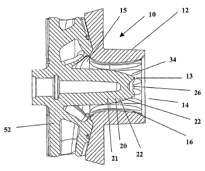
As best seen in Figures 2 to 5 there is shown apparatus generally indicated at
10 which
includes a stationary part 12 having a processing chamber 13 therein which has
an inner
side wall 16 , an inlet I4 and an outlet 15 and a rotatable part 20 which is
at least partially
disposed with the processing chamber 13 and includes an outer wall 21 which is
spaced
from the inner wall 16 of the processing chamber 13.
As best seen in Figure 5 the rotating part 20 is generally oval in cross
section. As a result
the distance between the outer wall 21,of the rotating part 20 and the inner
wall 16 of the
stationary part varies.
As best seen in Figures 2 and 3 the inner wall surface 16 of the processing
chamber 13 is
slightly tapered inwardly in the direction of the central axis thereof from
the inlet 14
towards the outlet 15.
As shown the rotatable part 20 of the apparatus projects into the processing
chamber 13
through the outlet end thereof. The rotatable part 20 is in the form of a proj
ection 22
having a tapering nose portion 26. As shown the projection 22 forms part of
the pump
impeller 52.
The apparatus includes an upstream connecting section which operatively
connects the
delivery pipe for the slurry to the stationary part 12. The connecting section
includes a
tapering chamber which tapers outwardly from the end of the delivery pipe to
the
stationary part. The cross-sectional dimension of the inlet to the processing
chamber is
about the same as the end of the connecting section adjacent thereto.
Grooves or recesses 32 and 34 are provided in the inner wall surface of the
processing
chamber 13 and the outer wall surface of the rotatable part 20. The grooves or
recesses 32
and 34 are circumferentially spaced around the wall surfaces and extend
generally in the
direction between the inlet and outlet of the processing chamber. The portions
of each part
CA 02446543 2003-11-06
WO 02/101245 PCT/AU02/00734
-5-
between adjacent grooves or recesses form elements for breaking down, grinding
or
crushing which continue to act on the slurry being processed.
In operation slurry is delivered to the pump SO via a conventional delivery
pipe or conduit
where it enters the processing chamber 13 of the stationary part 12 of the
apparatus via the
inlet 14. The rotating part 20 which forms part of the pump impeller 52 is
rotating within
the chamber 13. The tapered inner wall 16 of the chamber funnels the slurry
towards the
outlet 15 of the chamber and into contact with the rotating part. The
configuration of the
rotatable part in combination with the tapered inner wall of the processing
chamber causes
large solids within the slurry to be broken down to a size where they can pass
out of the
outlet and enter and pass through the pump. The edges of the grooves or
recesses in the
rotating part act as cutters on the solids in the slurry and cooperate with
the grooves in the
inner wall of the chamber to break down the solids in the slurry. The shape or
contour of
the rotating element has the effect of wedging and crushing the particles
jammed between
the stationary and rotating parts.
Finally, it is to be understood that alterations, modifications and/or
additions may be
incorporated into the various constructions and arrangements of parts without
departing
from the spirit or ambit of the invention.