Note: Descriptions are shown in the official language in which they were submitted.
CA 02446642 2003-11-06
WO 03/012948 PCT/GB02/03418
A DEVICE FOR PREVENTING CABLE DAMAGE DURING INSTALLATION
The present invention relates to the installation of cabling, and
more specifically to a device for preventing cable damage during
installation.
Twisted pair copper cabling has traditionally been used to carry
voice and data to end-users and typically hundreds of metres of cabling
has to be run above ceiling or underground to reach those users.
Potential damage-.to the cables during the installation process is a big
problem since if too great a force is exerted on these cables then the
twisted pair conductors inside the cabling insulating sheath are over
stretched. Consequently the distance between the twisted pairs will be
reduced giving rise to an increase in cross-talk and reducing the
effectiveness of the cables. Further one or more of the conductors may
even break.
Installers typically pull these cables in from 500 m drums. If for
example offices require four voice/data connection points, then installers
will in all likelihood pull from four drums at a time. Thus they are in
fact attempting to pull 2 km of cable from a standing start. This is
where damage is likely to occur.
The onset of Cat 6 / 7 standards has placed demands on manufacturers
for even greater performance and bandwidth. Cabling such Shielded Foiled
Twisted Pair (SFTP) has been developed to meet these increased demands.
With such cabling, each twisted pair conductor is surroura.ded by a layer of
aluminium foil. All the pairs are then covered by a further layer of foil
and then a braided shield of wires. This new configuration permits an
information transfer rate of approximately 200 Gigabytes per second as
opposed to the 100 Megabytes per second provided by the basic twisted pair
cabling. However such a transfer rate is even more highly dependent upon
the precise positioning of the twisted pair conductors within the cabling
sheath.
Such copper cables typically cannot retain their configuration if
stressed (pulled) beyond 50N (5 Kg). The cable manufacturers clearly
define the tolerances that their products can withstand and these are
typically:
1 x 4 pair cable pulled in by hand = 50N (5 Kg)
2 x 4 pair cables pulled in by hand = 75N
CA 02446642 2003-11-06
Pfl~'t't~d~'1 0'~~0(1u0063 ,C.?ESC~. ~N . C~2T49C15~~G~Q~C~3'4~~
..... "._.... .....F New Page: ~A18 June 2003
1
2
3 x 4 pairs cables pulled in by hand = 100N .
X x 4 pair cables pulled in by hand = X x 25 + 25N (up to a maximum of
200N)
Installing such cabling can prove extremely time consuming. Since
it will not be visibly obvious that a cable has been over stressed, an
installer will typically complete an installation and only discover that
the cable has become damaged when performing tests subsequently. They
will then have to start the process all over again, having wasted many
hours. The damaged cabling will also have to be replaced and this can
prove costly. Sophisticated cabling such as SFTP currently retails at
approximately ~185 a reel.
The installation process has proved problematic for many years and
not just with the copper cabling. When fibre cables first started to
appear, this issue was resolved by the introduction of pulling fuses such
as the type manufactured by Condux International, Inc.. Such a device is
attached between the cable being pulled and a pulling rope or cable. It
typically consists of two barrels linked together by an internal metal
break pin. The,metal pin is precisely manufactured to break when the
desired amount of stress or tension is exerted on the cable being pulled,
thus preventing internal damage to the cable. Different metal pins are
available dependent upon the break point required.
Unfortunately it is not possible to use such devices effectively
when installing fragile SFTP copper cabling. Fibre optic cabling is far
stronger, and so all these devices are made up of physical barrels which
will typically snap in half at between 667 and 8,006 N. This is far too
high a figure for the copper cable application and it is currently not
possible to manufacture metal pins which break under the much reduced
amount of strain required. This is because the thinner the metal pin is
made, the more difficult it becomes to control the break point.
Accordingly, the invention provides.a magnetic linkage for cable
installation, the linkage comprising: two components, which in operation
are held together by magnetic attraction, one of the components being
adapted to attach, via first attachment means, to the cable and the other
component being adapted to attach, via second attachment means, to a
pulling rope, the components further being adapted to break apart when a
predetermined pulling force is applied.
AMENDED SHEET ':21-QG ~p(~
CA 02446642 2003-11-06
x P~I~1~~C~:'~~ a~ ~GOOP , ~E~~r, ~ ~ (~'~~~~~J~~ ~~(~~Qc.~. ~~
.: ~:; .
-r- --- - - ° unv'i0063 ,., .. .._ New Page: 18 June 2003
3
As stated above, the type of cables t'o which the invention is
particularly applicable can be extremely fragile because the precise
positioning of the conductors within the cabling sheath is typically
important. If the cables are over stretched (i.e. the predetermined force
is exceeded), then the cables are likely to become damaged. The linkage
or cable pull of the present invention decouples when the predetermined
force is applied and breaks the pulling tension. The cable installer is
warned by the sudden reduction in the pulling tension that they were
dangerously close to damaging the cable, but no actual damage is done.
The installer is~able to quickly and easily reset the linkage and continue
with the installation., Such a linkage saves time because previously only
subsequent installation tests would determine that there was a problem
with the cable. (The damage is typically not visible but is contained
within the cabling sheath.) Further such cables are expensive and this
linkage therefore represents a huge cost saving by breaking before the
cables are themselves damaged.
In a preferred.embodiment the first component comprises a magnetic
portion and the second component comprises a magnetically attractable
portion. The magnetic portion comprises a permanent magnet having a
strength that will remain constant over the lifetime of the linkage
(unless it is recalibrated). The magnetically attractable portion
comprises a material which is attracted by the magnet (e. g. a ferrous
material such as iron). It will of course be appreciated that
alternatively two components each with magnetic portions could be used.
In a preferred embodiment the magnetically attractable portion of
the second component has a controlled contact area with the magnetic
portion of the first component. This contact area is used to control the
amount of force required to break the magnetic linkage. It will be
appreciated that it is also possible for the force required to break the
linkage to be set by controlling the strength of the magnetic portion of
the first component (or by a combination of both methods). However, it is
easier in.practice"to.machine the magnetically attractable portion of the
first component so that a particular configuration of the contact area
determines the load under which the two components decouple. The
calibration provided is in this way much more precise. One convenient way
is to configure the surface profile of the magnetically attractable
portion of the second component to provide the controlled contact area
with the magnetic portion of the first component. It is also possible to
machine the magnetic portion to control the contact area with the
magnetically attractable portion but this is not as straightforward a
AMENDED SHEET ,2v,t~~ ~0
CA 02446642 2003-11-06
~P1"1'tf~E:C~ CI'1 ~~ ~~Q(~3:'0063 3~ESC , ..~ ..
_. .. ., .. ,.. - -- New Page . 18 ~ June ~ 2 0 03
4
method because the magnet may be less easy to machine, and changes in the
shape of the magnet affect both the contact area and field strength.
In a preferred embodiment the first component has a male connector
which is inserted into a female connector on the second component to
provide the linkage (although the male and female components could of
course be reversed). The female connector is preferably a sheath of
circular cross-section which makes insertion of the male connector easier
by avoiding the need for any rotational.alignment when forming the
linkage. However a wide variety of other shapes and configurations could
also be used.
The male connector is preferably sized to fit snugly inside the
female connector. It will be appreciated that without this snug fit, it
would be possible for the two components to get separated from one another
during the installation process by a bending force that would tend to snap
the linkage sideways, rather than pulling it apart. The sheath therefore
holds the components in position regardless of any sideways forces exerted
on the linkage. This ensures that the linkage is only broken by a force
exerted in a direction parallel to the direction in which the cable is
being pulled. The flush fit between the first and second components also
makes it possible to reproduce the position in which the two components
couple to one another. This in turn ensures that a consistent breaking
force is required to separate the linkage.
In a preferred embodiment, the interior of the female connector has
a rim and in use the male connector is inserted into the female connector
until it abuts that rim. This precise positioning again helps to ensure a
consistent linkage force. The rim has a contact area which is controlled
in accordance with the desired predetermined force. The more material
that makes contact with the magnetic portion of the first component the
greater the force that is required to break the linkage. In one
embodiment the rim comprises a plurality of crenellations, which provide a
convenient way of controlling the,contact area by adjusting the spacing of
the crenellations.
Preferably, the first and/or second attachment means each include a
swivel piece. This allows for rotation of the linkage relative to the
cable axis during the pulling process, thereby preventing the cable from
becoming twisted during installation. Preferably the first and/or, second
attachment means includes a pivotable loop onto which the cable or pulling
AMEN~E~ SHEET ' 21.;6 2.~0
CA 02446642 2003-11-06
WO 03/012948 PCT/GB02/03418
rope (as appropriate) can be fastened. This provides flexibility and
reduces the risk of bending damage to the cable.
Tt will be appreciated that the tolerances that a particular cable
5 can withstand will typically vary dependent upon the type of cable and the
number of cables pulled together. Examples of these tolerances have been
given in the background section. Therefore one of the two components of
the magnetic linkage preferably includes a detachable sub-component to
allow replacement by another sub-component that provides a magnetic
attraction of different strength. between the two components.
In one preferred embodiment, the magnetic linkage is supplied with a
set of sub-components that are interchangeable into the linkage. Each
sub-component is calibrated to provide a different predetermined breaking
force. For example, the linkage can be supplied with a kit of three
different sub-components, one for each of the cabling loads mentioned in
the background section. Thus by way of example, there is one
sub-component where the predetermined force is 50N; one for 75N and one
for 100N (note, the predetermined force is preferably not more than 200N).
It will be appreciated that the invention is not limited to these precise
specifications and that any number of sub-components are possible.
Because one sub-component may be substituted for another, it is possible
for the linkage to be used in differing installation scenarios and also to
keep pace with new developments in the cabling industry. For example, if
a new and more fragile cable becomes available it will be possible to
manufacture a sub-component which will decouple from the second component
under a suitably low strain.
A pref erred embodiment of the present invention will now be
described, by way of example only, and with reference to the following
drawings:
Figures 1 and 2 show the device of the present invention at two
stages of operation in accordance with a preferred embodiment; and
Figures 3a and 3b show the interior of the magnetically attractable
component of the present invention in accordance with two preferred
embodiments.
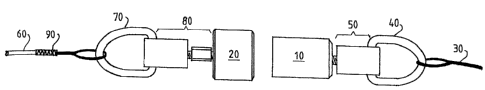
As shown in figure 1, a device has been designed having two
principal components: an open-ended steel barrel housing a magnet
(magnetic component 10?; and a magnetically attractable component 20. In
CA 02446642 2003-11-06
WO 03/012948 PCT/GB02/03418
6
use the two components are held together by the magnetic force of the
magnetic component. The magnetic component is attachable to a rope used
fox pulling 30 the cable, which is being installed, via a swivel piece 50
and a loop 40. The magnetically attractable component is attachable to
the cable itself 60 via swivel piece 80 and a loop 70. Typically the
cable is placed inside a metal grip 90 which tightens around the cable to
hold it securely in place. Tt is the metal grip which is actually
attached to loop 70. The swivel pieces are incorporated to allow for
movement of the cable during the pulling process, thereby preventing it
from becoming twisted during installation.
The magnetically attractable component has been precisely machined
such that placing the two principal components under a desired amount of
strain during installation will cause them to separate, thereby releasing
the tension on the cable before it becomes over stressed and damaged (see
figure 2). When the two components part, the tension is broken making the
installers quickly aware that they were exerting too great a force on the
cable.
Unlike the pulling fuses of the prior art it is possible to ensure
that the magnetic force holding the two components together is broken
under the comparatively low pulling loads listed in the background
section. The device is not dependent upon consumables such as replacement
broken metal pins and has few moving parts which are likely to require
substitution. It is consequently extremely robust. The device therefore
typically represents a one off cost to the installer. Further, the loops
and swivel pieces are preferably made out of a lightweight. material such
as aluminium and the two principle components are also relatively
lightweight. It is therefore possible. to manufacture such a device
weighing under 200 grammes in total. This is advantageous because it
means that it cannot damage the cables when it operates (i.e. if it falls
on the cables when the magnetic contact is broken).
Figures 3a and 3b show the machined interior of two magnetically
attractable components, each one designed to decouple from the magnetic
component when placed under a different level of stress. The magnetically
attractable component has an outer casing or sheath 100 which houses a
smaller barrel 110 with a rim 120, 125. The amount and thickness of the
material making up the rim is precisely manufactured to determine the
force under which the magnetic component and the magnetically attractable
component will separate. The more material that makes contact with the
magnetic component the greater the force that will be required. In Figure
CA 02446642 2003-11-06
WO 03/012948 PCT/GB02/03418
7
3a the rim 120 has a crenelated profile (the crenellations being shaded
and the gaps between the crenellations shown in white). Figure 3b shows a
complete rim 125 With no gaps and thus requires a greater force in
operation before the two components will decouple than the magnetically
attractable component shown in figure 3a. This is because in figure 3b
the surface area of the rim which actually makes contact with the magnetic
component is greater than in figure 3a. Thus the thickness of the rim
also is a determining factor.
Apart from precise machining, it is preferable to ensure that the
magnetic component makes a flush fit with the rim of the magnetically
attractable component. This is made possible by the outer casing which
enables the reproduction of the position in which the two components
couple to one another. This in turn ensures that a consistent breaking
force is required to separate the magnetic linkage. Further, it will be
appreciated that without snug fit possible due to the casing surrounding
the interior barrel of the magnetically attractable component, the two
components could get separated from one another during the installation
process by a bending force that would tend to snap the magnetic linkage
sideways, rather than pulling it apart. The casing therefore holds the
components in position regardless of any sideways forces exerted on the
linkage. This ensures that the linkage is only broken by a force exerted
in a direction parallel to the direction in which the cable is being
pulled. Of course if the magnetic coupling is broken under a load lighter
than is desirable, it is not damaging to the cable but is frustrating for
the installers who continually have to reset the device.
It should also be noted that the surface of the magnetic component
which makes contact with the magnetically attractable component should be
as free from contamination as is possible. This is because any
contaminants are also likely to cause the two components to break contact
with one another earlier than is desirable.
Preferably the device is stored as is shown in figure 1 with the two
components in contact with one another. This should prevent contamination
of the magnetic component. However, should the component become
contaminated then the surface of the magnetic component which makes
contact with the magnetically attractable component can simply be wiped
clean.
A further advantages of the preferred embodiment is that the swivel
pieces of the device 50, 80 allow their respective component to move with
CA 02446642 2003-11-06
WO 03/012948 PCT/GB02/03418
8
the pulling rope j cable. Moreover, the coupling device very compact and
is unlikely to catch on anything during the installation process.
To allow the device to be used with different magnetically
attractable components and thereby be resistant to different amounts of
strain, the magnetically attractable component has an aperture 130 for
receiving a threaded screw of swivel piece 80. It is therefore possible
to unscrew one magnetically attractable component and replace it with
another. In one embodiment the device is supplied with a kit of three
different magnetically attractable components. There is one magnetically
attractable component for each of the cabling loads mentioned in the
background section. It will be appreciated that the invention is not
limited to such and that any number of magnetically attractable components
are possible. Because one magnetically attractable component may be
substituted for another, it is possible for the device to be used in
differing installation scenarios and also to keep pace with new
developments in the cabling industry. For example, if a new and more
fragile cable becomes available it will be possible to manufacture a
magnetically attractable component which will part company with a magnetic
component under a suitably low strain.
It will be appreciated that whilst the invention has been described
primarily in terms of interchangeable magnetically attractable components,
it would be possible for the device to use interchangeable magnetic
components. With such an alternative design, the strength of the magnetic
component is. precisely controlled to set the force required to separate
'the two components. However, it is easier to machine the magnetically
attractable component such that a particular configuration of the area
Whl.Ch makes contact with the magnetic component controls the load under
which the two components separate. The control provided is in this way
more precise.
Further whilst the invention has been described in terms of its
applicability to SFTP copper cabling, it will be appreciated that the
invention is applicable to any type of cabling. As has been described, it
is however particularly suitable for protecting fragile cabling since it
is possible to cause the magnetic component and the magnetically
attractable component to separate from one another under a much lower
strain than the prior art devices.