Note: Descriptions are shown in the official language in which they were submitted.
CA 02446672 2003-11-05
WO 03/008167 PCT/US02/21263
APPARATUS AND METHOD FOR MIXING AND DISPENSING AN ADDITIVE-ENHANCED SLURRY
BACKGROUND OF THE INVENTION
The present invention relates to a method and apparatus for
preparing gypsum products (i.e., products comprising calcium sulfate
dehydrate) from starting materials comprising calcined gypsum (i.e.,
calcium sulfate hemihydrate or anhydrite) and water. More particularly,
the present invention relates to an improved apparatus for use in
conjunction with the slurry mixer typically used in supplying agitated
gypsum slurry to a wallboard production line. The basic technology of
gypsum wallboard manufacture is disclosed in U.S. Patent Nos. 1,500,452;
2,207,339; and 4,009,062 atl of which are incorporated by reference herein.
The present apparatus provides an improved mining chamber which
enhances the uniform mixing of foam into the gypsum slurry.
It is well known to produce gypsum products by uniformly
dispersing calcined gypsum in water to form a slurry and then casting the
slurry into a desired shaped mold or onto a surface and allowing the slurry
IS to set to form hardened gypsum by reaction of the calcined gypsum
1
CA 02446672 2003-11-05
WO 03/008167 PCT/US02/21263
(calcium sulfate henzihydrite or anhydrite) with the water to form hydrated
gypsum (calcium sulfate dihydrate). It is also well known to produce a
lightweight gypsum product by uniformly mixing an aqueous foam into
the slurry to produce air bubbles. This will result in a uniform distribution
of voids in the set gypsum product if the bubbles do not escape from the
slurry before the hardened gypsum forms. The voids lower the density of
the final product, which is often referred to as "foamed gypsum".
Prior apparatus and methods for addressing some of the
operational problems associated with the production of foamed gypsum
are disclosed in commonly-assigned U.S. Patent Nos. 5,638;635 and
5,643,510, which are incorporated by reference. The present invention
relates generally to the use of foamed gypsum in the production of gypsum
wallboard.
A gypsum wallboard mixer typically includes a housing
defining a mixing chamber with inlets for receiving calcined gypsum and
water, among other additives well known in the art. The mixer includes an
impeller or other type of agitator for agitating the contents to be mixed
into a mixture or slurry. Such mixers typically have a rectangular
discharge gate or slot with a cutoff block or door. The discharge gate
controls the flow of slurry from the mixer, and is difficult to adjust to
change slurry flow when product requirements change, such as when
thicker or thinner wallboard is desired.
2
CA 02446672 2003-11-05
WO 03/008167 PCT/US02/21263
Foam and/or other additives are generally added through a
foam slot on the outer side of the cut-off block and about 2-4 inches before
the gate's connection to a vertical canister and a donut or restrictor ring.
In the production of gypsum wallboard, a balance must be maintained in
that the foam is uniformly mixed into the slurry, but not broken down
from excessive agitation. Within the canister, which is approximately 5-7
inches in diameter, the material spins downward. The canister is
employed to reduce the flow pressure of the slurry discharged from the
mixer, which typically operates in the range of 270-300 rpm. One
drawback of such canisters is that a centrifugal force set up within the
canister causes separation between the materials in the mix due to density
differences.
More specifically, recent studies have shown that a vortex is
created as the mixture flows in the canister, which also creates an empty
air space in the canister. Such an air space is typically representative of
unwanted buildup of material in the canister, which then more easily sets
and causes clogging of the apparatus. Clogged mixing equipment causes
costly downtime for repairs.
Another disadvantage of the vortex created in the canister is
that higher density slurry components become separated from the
relatively lower density foam. Due to centrifugal force, the slurry is
pushed to the sides of the canister and the foam tends to stay in the middle.
3
CA 02446672 2003-11-05
WO 03/008167 PCT/US02/21263
Thus, rather than providing a site for the uniform mixing of the foam and
the slurry, the canister appears to be doing the opposite.
From the canister and donut ring, the material typically
flaws into a flexible, generally horizontal distribution boot, from where it
is dispensed onto the wallboard paper web traveling with the flow of
material. In some applications, the slurry is dispensed upon a previously
deposited layer of relatively denser gypsum slurry. If the pressure of the
dispensed slurry is too high, the prev~vusly deposited layer is disturbed,
resulting in a condition lmown as "washout".
Typically, a second facing is then applied on top of the
slurry to constitute the second face of the gypsum board Next, the
sandwich passes through a forming station which determines the width
and thickness of the gypsum board. This process is carried out in a
substantially continuous operation, and the gypsum slurry begins to set
immediately after the board is formed. Subsequently, the board is dried,
cut and bundled into commercially acceptable lengths. Since the uniform
mixing of foam within the slurry is a desired result in wallboard
manufacture, in view of the drawbacks of the canister, the only places
where the foam can rnix with the slurry are the mixer gate and the flexible
rubber boot.
4
CA 02446672 2003-11-05
WO 03/008167 PCT/US02/21263
Thus, it is an object of the present invention to provide an
improved gypsum slurry mixing apparatus which does not require a
canister.
Another object of the present invention of the present
invention is to provide an improved gypsum slurry mixing apparatus and
method which promotes uniform mixing of foam into the slurry.
Still another object of the present invention is to provide an
improved gypsum slurry mixing apparatus and method which causes a
reduction in slurry flow pressure prior to discharge of the mixture upon the
wallboard paper and at the same time promotes even mixing of foam into
the slurry.
A further object of the present invention is to provide an
improved gypsum slurry mixing apparatus and method which reduces
maintenance of mixing and dispensing equipment due to premature setting
of the slurry.
A still further object of the present invention is to provide an
improved gypsum slurry mixing apparatus and method which increases
slurryJfoam mining time while not requiring additional length of the board
production line.
Yet another object of the present invention is to provide an
improved gypsum slurry mixing apparatus and method which provides an
5
CA 02446672 2003-11-05
WO 03/008167 PCT/US02/21263
easily accessible mechanism for changing the volume of slurry emitted
from the mixer.
BRIEF SUMMARY OF THE lNUENTION
Accordingly, the above-listed objects are met or exceeded by
the present apparatus and method for controlling the output of a slurry
mixer including the features of eliminating the canister and its undesirable
vortex and replacing it with an extended mixing and dispensing apparatus.
The extended mixing and dispensing apparatus gate preferably includes an
elongate, preferably flexible conduit which provides additional space for
uniform mixing of slurry and additives such as foam, retarders, dispersants
and accelerators. By providing a flexible mixing chamber in the conduit,
unwanted premature setting of the gypsum is prevented so that
occurrences of mixer or conduit lumps andlor paper breaks are reduced.
Also, coiling of the chamber is available for applications in which there is
limited space in the board line between the mixer outlet and the board
forming plate. In the latter application, an extended length mixing
chamber is provided which is applicable with board lines having limited
space.
Another feature of the present invention is the inclusion of
an adjustable pinch or concentric valve located in the preferably flexible
s
CA 02446672 2003-11-05
WO 03/008167 PCT/US02/21263
conduit for regulating slurry flow to create backpressure in the mixer,
which further enhances the uniform mixing action of the foam and slurry.
This backpressure also keeps the mixer filled with slurry and thus prevents
unwanted premature setting and clogging. When the valve is a concentric
valve, it exerts a uniform pressure around the entire circumference of the
conduit, which also reduces premature setting and clogging. Regardless of
the type of valve; the use of a valve in association with the flexible conduit
provides a convenient way to change the volume of dispensed slurry and
thus adjust the thickness of produced wallboard as a result.
Yet another feature is the provision of a shock-absorbing
device as a part of the conduit to reduce the force or pressure of the
dispensed slurry upon the receiving web of substrate or previously
dispensed slurry. In the preferred embodiment, the shock-absorbing
device takes the form of a generally "S " or "C"-shaped double bend
I S formation.
More specifically, an apparatus for delivering an additive-
enhanced slurry for use in making gypsum wallboard, and configured for
connection to a. centrifugal mixer with a tangential discharge outlet,
includes a conduit having a main inlet in slurry receiving communication
with the miner outlet and extending to a spout for discharging the slurry
proximate a wallboard forming area. At least one volume restrictor is
associated with the conduit for creating backpressure between the volume
7
CA 02446672 2003-11-05
WO 03/008167 PCT/US02/21263
restrictor and the mixer outlet for keeping the mixer full, and at least one
pressure reducer is associated with the discharge spout and configured for
reducing the pressure of the slurry dispensed from the discharge spout.
The apparatus is configured for maintaining a generally laminar flow from
the mixer outlet to the discharge spout.
In the preferred embodiment, the dispensing apparatus is
provided with at least one preferably adjustable valve for creating
backpressure in the conduit and mixer, for controlling the flaw of slurry
from the spout and for reducing buildup of slurry in the apparatus and the
mixer. It is preferred that the apparatus, including the preferably flexible
conduit portion, be connected directly to the mixer outlet so that generally
laminar flow is preserved from the mixer to the dispensing point on the
wallboard production line.
In still another embodiment, a method for providing an
evenly mixed additive enhanced slurry to a web is provided, including
inserting calcined gypsum and water into a mixing chamber of a mixer
through one or more inlets of the mixing chamber, agitating the contents
of the mixing chamber to form an aqueous dispersion of the caicined
gypsum, emitting the agitated contents from an outlet of the mixer,
2fl passing the agitated contents into a dispensing apparatus, introducing an
aqueous foam into the mixture, creating a backpressure on the mixture in
the apparatus' by reducing the volume of mixture being emitted from a
8
CA 02446672 2003-11-05
WO 03/008167 PCT/US02/21263
conduit of the apparatus, the back-pressure being created by constricting
the conduit, and controlling the pressure of slurry and foam dispensed
from the spout.
BRIEF DESCRIPTION OF THE SEVERAL VIEWS
OF THE DRAWINGS
FIG. 1 is a fragmentary schematic overhead plan view of a
mixing apparatus incorporating the features of the invention;
FIG. 2 is a side elevational view of a pressure reducing
apparatus taken along the line 2-2 of FIG. 1 and in the direction indicated
generally;
FIG. 3 is a front elevational view of the apparatus of FIG. 2;
FIG. 4 is a fragmentary side elevational view of an alternate
to the structure shown in FIG. 2;
FIG. 5 is a fragmentary overhead plan view of a alternate
embodiment of the apparatus of FIG. 1;
FIG. 6 is a fragmentary overhead plan view of another
alternate embodiment of the apparatus of FIG. l;
FIG. 7 is a fragmentary overhead plan view of still another
alternate embodiment of the apparatus of FIG. 1;
FIG. 8 is a fragmentary overhead plan view of a further
alternate embodiment of the apparatus of FIG. l;
9
CA 02446672 2003-11-05
WO 03/008167 PCT/US02/21263
FIG. 9 is a section taken along the line 9-9 of FIG. 8 and in
the direction indicated generally; and
FIG. 10 is a fragmentary perspective elevational view of
another alternate embodiment of the apparatus of FIG. 1.
DETAILED DESCRIPTION OF THE INVENTION
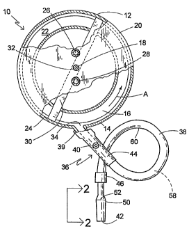
RefeiTixig now to FIG.1, a mixing apparatus for mixing and
dispensing a slurry is generally designated 10 and includes a mixer 12
having a housing 14 configured for receiving and mixing the slurry. The
housing 14 defines a mixing chamber 16 which is preferably generally
cylindrical in shape, has a generally vertical axis i8, and upper radial wall
20, a lower radial wall 22 and an annular peripheral wall 24. An inlet 26
for calcined gypsum and an inlet 28 for water are both positioned the
upper radial wall 20 proximate the vertical axis 18. It should be
appreciated that the inlets 26, 28 are connected to gypsum and water
supply containers respectively (not shown), such that gypsum and water
can be supplied to the mixing chamber 16 by simple gravity feed. Also, as
is well lrnown in the art, other materials or additives in addition to gypsum
and water, often employed in slurries to prepare gypsum products (e.g.~.
accelerators, retarders, fillers, starch, binders, strengtheners, etc.) can
also
be supplied through these or other inlets similarly positioned.
CA 02446672 2003-11-05
WO 03/008167 PCT/US02/21263
An agitator 30 is disposed in the mixing chamber 16 and has
a generally vertical drive shaft 32 positioned concentrically with the
vertical axis 1 ~ and extends through the upper radial wall 20. The shaft 32
is connected to a conventional drive source such as a motor for rotating the
shaft at whatever speed is appropriate fox agitatiug the agitator 30 to mix
the contents of the mixing chamber 16. Speeds in the range of 275-300
rpm are common. This rotation directs the resulting aqueous slurry in a
generally centrifugal direction, such as in a counter-clockwise outward
spiral indicated by the arrow A. It should be appreciated that this
depiction of an agitator is relatively simplistic and meant only to indicate
the basic principles of agitators commonly employed in gypsum slurry
mixing chambers known in the art. Alternative agitator designs, including
those employing pins or paddles, are contemplated.
An outlet 34, also referred to as a mixer outlet, a discharge
gate or a slot, is provided in the peripheral wall 24 for the discharge of the
major portion of the well-mixed slurry into what is generally referred to
herein as a mixing and dispensing apparatus 36. While conventional
outlets are typically rectangular in cross-section, the present outlet 34 is
preferably circular in cross-section, however other shapes are
contemplated depending on the application. Also, while it is contemplated
that the specific configuration of the mixer 12 may vary, it is preferred that
the present mixer is of the centrifugal type commonly used in the
i1
CA 02446672 2003-11-05
WO 03/008167 PCT/US02/21263
manufacture of gypsum wallboard, and also of the type in which the outlet
34 dispenses the slurry tangentially to the housing 14. While conventional
mixers typical provide a cutoff block at the outlet 34 to mechanically
adjust the flow of slurry for the desired thickness of wallboard, typically
ranging from'/a" to 1 ", it has been found that such a block often provides a
site for the premature setting of gypsum, resulting in slurry buildup and
eventual clogging and disruption of the production line.
Another drawback of conventional cutoff blocks is that
when the gate is set for thick wallboard and a conversion is made to thin
wallboard, where the block is disposed to permit relatively free flow of
slurry from the outlet, insufficient backpressure is provided in the mixing
chamber 16 which results in an incomplete and nonuniform mixing of
slurry constituents. Also, inadequate backpressure results in dead spots or
slow spots in the centrifugal internal flow in the mixing chamber 16,
1 S causing premature setup of the slurry and unwanted lumps in the mixture.
In such instances, the wallboard line must be shut down for maintenance,
causing inefficiencies in production.
'Fhe mixing and dispensing apparatus 36 includes an
elongate, preferably cylindrical tube or conduit 3~ and having a main inlet
39 in slurry receiving communication with the mixer outlet 34, and has an
additive inlet 40 such as a nipple for the introduction of aqueous foam or
other desired additive, such as retarders, accelerators, dispersants, starch,
12
CA 02446672 2003-11-05
WO 03/008167 PCT/US02/21263
binders, and strength-enhancing products such as poly- phosphates,
typically sodium trimetaphosphate, all of which are known in the
wallboard art, after the slurry has been substantially mixed. It is desired
that when foam is the additive, it is uniformly mixed in the slurry but not
excessively agitated to the extent that it is broken down. As such, it is
common to introduce the foam into the additive inlet 40 just after or
downstream of, yet close to the outlet 34 and the main inlet 39 to prolong
mixing time with the slurry. However, depending on the particular
application, it is contemplated that the additive such as foam may be
introduced at other places along the apparatus 36.
It is preferred that the mixing and dispensing apparatus 36
be in the range of at least 48 inches (120 cm), however it is contemplated
that the length may vary depending on the particular application and the
constraints of the particular gypsum wallboard production line. The
extended length of the mixing and dispensing apparatus 36 is desirable for
providing time for the foam to rnix uniformly with the slurry after the
point of additive introduction, and prior to dispensing the slurry upon a
wallboard forming area such as the web ofwallboard paper or upon a
previously dispensed layer of relatively denser gypsum slurry, also
deposited upon a web of wallboard paper. Since the preferred application
for the present invention is a gypsum wallboard production line, the
13
CA 02446672 2003-11-05
WO 03/008167 PCT/US02/21263
gypsum slurry with additives is commonly dispensed or discharged upon
such a web.
A feature of the present mixing apparatus 10 is that the
conduit 38 is placed in fluid communication with the outlet 34
downstream from the introduction of foam at the inlet 40, and includes a
discharge spout 42 for dispensing the slurry upon the web as described
above. The conduit 38 is preferably a flexible hose of rubber or rubber-
like material (although rigid conduits are contemplated) and is of
sufficient length to provide extra time for the foam or other additive to
become more uniformly mixed within the slurry. While rigid conduits are
also contemplated, best results have been obtained using hoses which are
double reinforced to avoid kinldng, preferably having a smooth inner
surface, and being dimensioned in the range of 11/2-3 inches (3.75 - 7.5
cm) inner diameter. Other diameters are contemplated to suit the
application. In the present invention, a preferably relatively rigid additive
inlet portion 44 bearing the inlet nipple 40 is in the approximate range of
6-24 inches (15-60 cm), and with the preferably flexible conduit 38, has a
total length at least in the approximate range of 50 to 168 inches (125 -
420 cm), while longer lengths are contemplated, such as when increased
slurry residence time is desired for more complete mixing. It is
contemplated that in some applications, the additive inlet portion 44 is also
made of flexible, rubber-like material and is in the shape of a hose. When
14
CA 02446672 2003-11-05
WO 03/008167 PCT/US02/21263
the additive inlet portion 44 and the conduit 3~ are made of dissimilar
materials, they are joined to each other with adhesives, clamps, ultrasonic
welding or other known fastening technologies in a way which will
provide a smooth transition and which minimizes internal obstructions
which might provide a site for the collection and premature setting of
slurry.
As discussed above, another drawback of conventional
gypsum slurry mixing apparatuses is that a canister is required
downstream of the discharge gate to evenly mix the foam with the slurry
and to reduce the slurry pressure . Another goal of the present invention is
to eliminate the canister and its inherent problems. Accordingly, the
present mixing and dispensing apparatus 36 is configured to maintain a
generally laminar flow of the slurry from the main inlet 39 to the discharge
spout 42 without a flow disrupter in the nature of the prior canisters. In.
the present invention, "laminar flow" is understood to mean a smooth,
non-spiraling pipe flow that maintains full cross-sectional area of the
conduit 3~ through which it passes. This is in contrast to the turbulent
flow of the prior canisters, in which uneven mixing of additives and slurry
often occurred.
As will be described below, the flexibility of the present
mixing and dispensing apparatus 36, and specifically the conduit 38
permits coiled or serpentine configurations that extend the length of the
CA 02446672 2003-11-05
WO 03/008167 PCT/US02/21263
mixing chamber 16, and thus increase the residence time in which the
foam and/or other additive can completely mix with the slurry without
requiring a longer production line. Unlike conventional wallboard mixing
apparatuses, in the present invention the conduit 38 of the mixing and
dispensing apparatus 36 is dixectly connected to the gate portion 44, and
ultimately to the outlet 34 without intervening devices such as a canister.
Also, the preferably flexible construction of at least a portion of the
conduit 38 reduces the tendency for gypsum to prematurely set up in the
interior and cause undesirable clogging.
.Another feature provided in some embodiments of the
present mixing apparatus 10 is at least one flow restrictor 46 associated
with the mixing and dispensing apparatus 36 for creating backpressure in
the gate and ultimately in the mixing chamber i6, for controlling the flow
of slurry from the spout 42 and for at least reducing and generally
preventing the buildup of slurry in the gate and the mixer. In the preferred
embodiment, the restrictor 46 is of the type which exerts an even, circular
or concentric clamping force on the flexible conduit 38. Also, the
preferred restrictor 46 exerts its clamping force on the exterior of the
conduit 38, so that an internal passageway of the conduit is not obstructed
by valve components.
The preferred restrictor 46 is a dynamically adjustable valve,
i.e., is adjustable while the mixer 12 is in operation and slurry is being
16
CA 02446672 2003-11-05
WO 03/008167 PCT/US02/21263
emitted from the spout 42, and is taken from the group consisting of pinch
valves, muscle valves, concentric valves, iris-action valves and butterfly
valves. In some low-pressure applications, simple hose clamps are also
suitable. It is contemplated towse a transition between a larger diameter
hose to a smaller diameter hose section as the restrictor 46 for reducing the
volume of dispensed slurry, and for creating backpressure. For best
results, the valve 46 is located on the conduit 38 near the spout 42 to
provide the most efficient use of the length of the conduit for complete
mixing of the foam into the slurry, however other locations farther from
the spout are contemplated depending on the application.
Referring now to FIGS. 1-3, a further feature of the present
mixing apparatus 10 is a pressure reducing apparatus 50 in the mixing and
dispensing apparatus 36 for reducing the pressure or force of the slurry
being dispensed from the spout 42. A typical mixer 12 of the type used
with the present invention generates a slurry velocity in the approximate
range of 700-2200 ft/min, measured at the discharge gate or outlet 34 with
a corresponding force or pressure. Unless this force or pressure is reduced
significantly, the force of the output of the spout 42 will disrupt the
distribution of the previously deposited slurry, causing the above-
described "washout", and will result in uneven wallboard. Thus, the
pressure reducer 50 is needed so that the discharge from the spout 42 is
acceptably slow and even.
17
CA 02446672 2003-11-05
WO 03/008167 PCT/US02/21263
In the preferred embodiment, the pressure reducer 50 is
disposed in close association with the spout 42 and generally defines a pair
of right angle bends 52, 54 in the conduit 38. It is also contemplated that
approximate right angles may be suitable in certain applications, such as
where the mixer outlet pressure is relatively lower. While the present
pressure reducer 50 is generally "S"-shaped when viewed from the side
(the opposite side shown in FIG. 2), it may also be "C"-shaped (FIG. 10),
the objective is to cause the flow of slurry in the conduit 38 to undergo at
least one and preferably at least two approximate right angle deflections
prior to exiting the spout 42. Each successive right angle deflection will
further reduce the output pressure of the slurry measured at the spout 42.
It has also been found that positioning the conduit 38 to have an upwardly
extending portion causes gravitational forces to reduce the pressure of the
slurry.
Between the right angle portions 52, 54 is a preferably
vertical transition leg 56. It has been found that slurry buildups between
the portions 52, 54 are reduced when the transition leg 56 is more vertical.
If the transition leg 56 is oriented at more than a 10° angle from
vertical,
the potential for slurry buildup will increase.
As seen in FIG. 3, the spout 42 is slightly flared from the
diameter of the hose 40. It is recommended that the diameter of the
pressure reducer 50 is at least equivalent to the diameter of the conduit 38
18
CA 02446672 2003-11-05
WO 03/008167 PCT/US02/21263
to facilitate even slurry flow. In addition, sufficient brackets 57 (best seen
in FIG. 10) should be provided to support the conduit 38 as well as the
pressure reducer SO to prevent buildups and premature setting of slurry in
the pressure reducer due to the resulting backpressure intentionally caused
S by this pressure reducer shape.
Referring now to FIG. 4, an alternate pressure reducer
configuration is designated 50', and basically represents a structure where
the angled portions 52' and 54' are greater than right angles to form a
"hump" shape for reducing slurry flow pressure.
It is contemplated that the pressure reducer 50 is made of a
flexible polymeric material which is compatible with the conduit 38 and is
securely and sealingly fastenable thereto by chemical adhesives, epoxy,
sonic welding, heat staking or equivalent polymeric fastening technology.
For best results, the pressure reducer 50 is located downstream of the
valve 46, with the valve behveen the pressure reducer and the outlet 34,
although other arrangements are contemplated depending on the
application.
Referring now to FIGS. l and 5-10, it will be seen that the
present mixing apparatus 10 may be provided in a variety of mixing and
dispensing apparatus 36 configurations, particularly in the arrangement
and length of the conduit 38. In all of the embodiments described below,
identical components are designated with corresponding reference
19
CA 02446672 2003-11-05
WO 03/008167 PCT/US02/21263
numbers. Factors which influence the particular configuration of the
conduit 38 employed include, among other things, the thickness of the
wallboard being produced, the distance between the mixer 12, the mixer
outlet 34 and the wallboard forming plate, and the particular
S characteristics of the slurry formulation, including the setting rate, the
water/stucco ratio, glass fiber usage and the percentage of foam desired.
Some of the present embodiments may be more successful than others,
depending on the particular wallboard production line.
In all embodiments, it is preferred that any transitions or
joints between hoses or components in the interior passageway 58 of the
gate,portion 44, the conduit 38 and or the pressure reducer 50 should be
smooth and minimize steps or obstructions which tend to encourage slurry
buildup. Also, during operation, it has been found that periods of low
slurry flow volume tend to increase the potential for slurry buildup, and
this can be regulated by restricting or closing down the valve 46, or using
a smaller diameter conduit 38 and/or additive inlet portion 44.
In FIG. l, the additive inlet portion 44 is relatively rigid and
includes the inlet nipple 40. The flexible portion of the conduit 38 is
secured to the additive inlet portion 44 in a way which minimizes internal
obstructions, as is known in the art, and forms a loop 60 to provide a
satisfactory amount of time for mixing in the foam into the slurry in
applications where length is at a premium on the wallboard forming table
CA 02446672 2003-11-05
WO 03/008167 PCT/US02/21263
62 (best seen in FIG. 10) between the mixer 12, the mixer outlet 34 and
the board forming plate (not shown) of the wallboard forming area.
Referring now to FIG. 5, the apparatus is generally
designated 36a, features a curved gate portion 44a, and foam is introduced
through an injection ring ox block 64 (best seen in FIGS. 8 and 9). A
plurality and preferably three foam injection ports 66 (best seen in FIG. 9)
are employed for injecting foam into the main slurry flow passageway 58.
A pressure sensor 70 is used to trigger the pinch valve 46, which is
contemplated as being~automatically or manually adjustable while the
apparatus 10 is dispensing slurry. A wide mouthed bell formation 72 may
be used to reduce slurry pressure;"either alone or in conjunction with the
pressure reducer 50 (FIG. 2).
Referring now to FIG. 6, a variation of the configuration of
FiG. 1 is shown, and the apparatus is generally designated 36b, which
features a conduit 38b fashioned into a zig-zag or "S"-shape when viewed
from above. Note that in this embodiment, the spout 42 is approximately
equidistant from an end 74 of the gate portion 44b. An advantage of the
configuration of the conduit 38b over the conduit 38 is that additional
length can be provided in a shorter distance from the mixer 12, which is
useful in board lines in which space is at a premium. Also, in this
embodiment it will be appreciated that the spout 42 is vertically displaced
below the gate portion 44b and also below a main leg 76 of the conduit
21
CA 02446672 2003-11-05
WO 03/008167 PCT/US02/21263
38b. In developing space-saving configurations for the conduits 38, 38a,
38b, etc., care must be taken to avoid creating kinks which can cause flow
disruptions or collect slurry and cause premature setting and clogging.
Referring now to FIG. 7, the apparatus is generally
designated 36c and the conduit 38c is provided in a loop formation 60c
which spirals up above the mixer 12. It will be appreciated that the loop
formation 60c can as easily be spiraled below the mixer 12, depending on
the application. It is contemplated that in some applications the conduit
38 may be bifurcated, with a pair of legs 78 provided prior to the
attachment of the pressure-reducing portion 50.
Referring now to FIGs. 8 and 9, a mixing and dispensing
apparatus 36d having a conduit 38d is shown with a relatively flexible gate
portion 44d, feeding into. the foam injection block 64 and then into the
pressure sensor 70 and the .concentric valve 46. A feature of the mixing
i5 and dispensing apparatus 36d is that the pressure reducer SOd, in defining
its "S"-shape, has both a vertical and a horizontal displacement from the
valve 46.
Referring now to FIG. i0, a mixing and dispensing
apparatus 36e is shown disposed above a conventional gypsum wallboard
line 80 including a conveyor table 82 upon which a web of face paper 84
is moved upon a conveyor in a direction designated by the arrow D.
The mixer 12 is shown supported by a frame member 86, which can be
22
CA 02446672 2003-11-05
WO 03/008167 PCT/US02/21263
any sort of frame or platform sufficient fox supporting the mixer and other
associated equipment as is known in the art.
The mixing and dispensing apparatus 36e is shown having
sufficient length to wrap at least partially around the mixer 12. A feature
of this embodiment is that the spout 42e is located upstream on the
wallboard production line or table 82 of the mixer outlet 34, for
applications with extremely limited space between the mixer 12 and the
forming plate. When running the conduit hose 38e around the mixer 12,~ it
is important to adequately support the hose, such as with the brackets 57,
so that there are no dips or low areas along its path. As depicted in the
embodiment of FIG. 7, a bifurcated pressure reducer 50e is shown with the
pair of legs 78 and a 90 ° angle 54e. The other angle 54e is located
above
and to the rear of the mixer 12. This embodiment also lacks the valve 46.
Slurry S is shown being dispensed from the spout 42e upon the web of
paper 84, which may be provided with a layer of previously deposited
denser gypsum slurry 88 (shown fragmentarily). In all of the
embodiments, to ensure that slurry buildups are not occurring, it is
recommended that operators periodically squeeze the conduit 38 and/or
the spout 42, such as every 15 minutes or so.
In. operation, it will be seen that a system for providing an
evenly mixed slurry to a web is provided, including inserting calcined
gypsum and water into the mixing chamber 16 through one or more inlets
23
CA 02446672 2003-11-05
WO 03/008167 PCT/US02/21263
26, 28 of the mixing chamber, agitating the contents of the mixing
chamber to form an aqueous dispersion of the calcined gypsum, emitting
the agitated contents from the outlet 34 of the mixer 12, passing the
agitated contents into the main inlet 39 of the mixing and dispensing
apparatus 36, 36a-e, introducing an aqueous foam into the mixture at the
gate, preferably through the inlet nipple 40, creating a backpressure on the
mixture in the gate by constricting the area of mixture being emitted from
the flexible conduit 38, 38a-a of the gate, the backpressure being created
by constricting the conduit 38, such as with the valve 46, and controlling
the pressure of slurry and additive dispensed from the spout 42, 42c, 42e
such as by the pressure reducer 50 in its various configurations. In the
preferred embodiment, the slurry pressure is reduced by being forced to
change direction approximately 90° at least once and preferably twice.
Where possible, the flexible conduit 38 extends generally
directly down the board line. The longer the conduit 38, the more even is
the mixing of the foam with the slurry. It is contemplated that the conduit
38 may extend linearly at least as much as 60 inches (150 cm) past the
mixer 12. For board line applications where there is insufficient space
before the forming plate is encountered, a set-up as depicted in FIG. 10 is
recommended. The benefits of improved foam/slurry mixing achieved by
the present invention include: reduction and/or elimination of blisters in
the boaxd; uniformity of the board, leading to improved strength; and
24
CA 02446672 2003-11-05
WO 03/008167 PCT/US02/21263
potential water reduction from the board formulation, which in turn will
led to energy savings in the kiln or an increase in line speed.
While specific embodiments of the slurry mixer outlet of the
pxesent invention have been shown and described, it will be appreciated by
those skilled in the art that changes and modifications may be made
thereto without departing from the invention in its broader aspects and as
set forth in the following claims.