Note: Descriptions are shown in the official language in which they were submitted.
CA 02446834 2003-10-27
, 4
TOROIDAL WAVEGUIDE FOR A
MICROWAVE COOKING APPLIANCE
BACKGROUND OF THE INVENTION
1. Field of Invention
The present invention pertains to the art of cooking appliances and,
more particularly, to a microwave energy delivery system including a
toroidal waveguide which efficiently delivers a substantially uniform
microwave energy field into a cooking chamber.
2. Discussion of Prior Art
l0 Cooking appliances utilizing directed microwave energy fields to
cook food items have existed for some time. In general, a cooking
process is performed by heating the food item by directing a standing
microwave energy field into an oven cavity such that the microwave
energy field reflects about the oven cavity and impinges upon the food
1
CA 02446834 2003-10-27
i
item. As the microwave energy field impinges upon the food item, the
field is converted into heat through two mechanisms. The first, ionic
heating is caused by the liner acceleration of ions, generally in the form
of salts present within the food item. The second is the molecular
excitation of polar molecules, primarily water, present within the food
item. However, the nature of the standing waves results in localized areas
of high and low energy which cause the food to cook unevenly. This is
especially true in larger ovens where the size of the cavity requires a
more uniform energy distribution in order to properly cook the food. To
attain an even or uniform energy distribution, the microwave energy must
be introduced into the oven cavity in a manner which creates a
constructive standing wave front which will propagate about the oven
cavity in a random fashion.
Various methods of directing microwaves into cooking chambers
to minimize hot and cold areas resulting from the existence of high and
low energy fields have been proposed in the prior art. These methods
range from altering the pattern of the standing waves by varying the
frequency of the microwave energy field, to incorporating a stationary
mode stirrer which simulates change in the geometric space of the
cooking chamber. Methods of changing the wave pattern have also
included the incorporation of a rotating blade stirrer which functions to
deflect microwave energy into a cooking cavity in various patterns.
Traditionally, stirrers have been located in various points in the
microwave feed system, ranging from adjacent to a microwave energy
source to a position within the cooking chamber itself. Some stirrers
include various openings which are provided to disperse standing waves,
and others have various surface configurations designed to reflect the
2
CA 02446834 2003-10-27
standing waves. Stirrers are either driven by a motor or by air currents
supplied by a blower. In any event, all of these methods share a common
theme, i.e., to reflect and/or deflect the microwave energy into a cooking
cavity such that a uniform distribution of standing wave patterns can be
achieved.
Other methods of controlling the standing waves include
modifying the structure of the waveguide itself. The prior art provides
examples of waveguides shown as cylinders, square boxes, and a variety
of other configurations designed to cause the standing waves to interfere
l0 with one another in a manner which results in a randomized wave front
such that a maximum energy field is directed into the cooking chamber.
Other designs include matching the dimensions of the waveguide to the
wavelengths of the standing wave pattern. However, these designs, while
effective to a point, have failed to adequately address the problem of
15 energy loss due to energy absorption on the waveguide surface.
As the desire to increase the sizes of oven cavities has risen, and
microwave technology has been combined into conventional or
convection ovens, the uniform distribution of the standing waves has
become of even greater concern. For this reason, manufacturers have
20 modified their designs to include multiple magnetrons, multiple stirrers,
and motor driven, variable speed stirrers, all of which are intended to
create a random wave pattern thought to be of a more uniform character.
Still other designs include structure for rotating or moving food within
the cooking chamber. Ovens employing this method, position the food
25 on a platter which is rotated through the standing wave patterns such that
the food is more uniformly exposed to the microwaves.
CA 02446834 2003-10-27
While these methods are fine for smaller ovens, they are hardly
practical for larger, conventional, ovens where space is more of a
concern. Certainly, in an age where energy consumption is of particular
concern, the need for an energy efficient cooking appliance is desired.
Based on the above, there exists a need for a microwave delivery system
which will direct a uniform standing wave pattern into a cooking chamber
in a manner that minimizes energy losses within a waveguide, yet
provides a uniform, maximum energy field to the cooking chamber.
SUMMARY OF THE INVENTION
to The present invention is directed to a microwave cooking appliance
including a toroidal-shaped waveguide preferably having a ring diameter
equal to twice the standing wavelength, and a cross-sectional diameter
equal to one-half the standing wavelength. The design of the waveguide
causes a standing wave to impinge upon an inner surface of the
waveguide at points of zero energy such that energy absorbed by the
waveguide is minimized. Additionally, the design of the ring diameter
causes constructive interferences within the waveguide, thereby a high
energy node about the circumference of the waveguide. Furthermore, a
plurality of cavity excitation ports are arranged about the bottom portion
of the waveguide.
In accordance with a preferred embodiment, the microwave
delivery system of the present invention further includes a mode stirrer
having a plurality of openings evenly spaced about the periphery of the
stirrer. Specifically, when rotated, the openings operate as shutters. As
4
CA 02446834 2003-10-27
the openings align with the cavity excitation ports, passages are created to
allow the microwave energy field into the cooking chamber. The
operation of the stirrer creates a uniform pattern of microwave energy to
be directed onto a food item placed within the cooking chamber.
In any event, additional objects, features and advantages of the
invention will become more readily apparent from the following detailed
description of a preferred embodiment of the invention, when taken in
conjunction with the drawings wherein like reference numerals refer to
corresponding parts in the several views.
l0 BRIEF DESCRIPTION OF THE DRAWINGS
Figure 1 is a perspective view of a combination
microwave/convection wall oven including a toroidal waveguide
constructed in accordance with the present invention;
Figure 2 is a perspective view of the toroidal waveguide mounted
in accordance with the present invention;
Figure 3 is a partial cross-sectional view of the toroidal waveguide
of Figure 2; and
Figure 4 is a cross-sectional view of the toroidal waveguide of
Figure 3 inverted.
5
CA 02446834 2003-10-27
r
DETAILED DESCRIPTION OF THE INVENTION
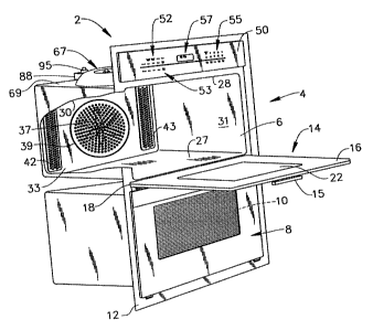
With initial reference to Figure 1, a microwave cooking appliance
constructed in accordance with the present invention is generally
indicated at 2. Although the form of cooking appliance 2 in accordance
with the present invention can vary, the invention is shown in connection
with cooking appliance 2 depicted as a wall oven. More specifically, in
the embodiment shown, cooking appliance 2 constitutes a dual oven wall
unit including an upper oven 4 having upper cooking chamber 6 and a
lower oven 8 having a lower cooking chamber 10. In the embodiment
shown, upper oven 4 is adapted to perform a rapid cook or combination
microwave/convection cooking process, and lower oven 8 is provided to
perform a standard convection and/or radiant heat cooking operation. As
shown, cooking appliance 2 includes an outer frame 12 for supporting
upper and lower cooking chambers 6 and 10.
In a manner known in the art, a door assembly 14 is provided to
selectively provide access to upper cooking chamber 6. As shown, door
assembly 14 is provided with a handle 15 at an upper portion 16 thereof.
Door assembly 14 is adapted to pivot at a lower portion 18 to enable
selective access to within cooking chamber 6. In a manner also known in
the art, door 14 is provided with a transparent zone 22 for viewing
cooking chamber 6 while door 14 is closed.
As best seen in Figure 1, cooking chamber 6 is defined by a bottom
portion 27, an upper portion 28, opposing side portions 30 and 31, and a
rear portion 33. Bottom portion 27 is preferably constituted by a flat,
smooth surface designed to improve the cleanability, serviceability, and
6
CA 02446834 2003-10-27
reflective qualities of cooking chamber 6. In the embodiment shown,
arranged on rear portion 33 is a convection fan 37 having a perforated
cover 39 through which heated air can be withdrawn from cooking
chamber 6. Heated air is re-introduced into cooking chamber 6 through
vents 42 and 43 arranged on either side of fan 37. Although cooking
appliance 2 is depicted as a wall oven, it should be understood that the
present invention is not limited to this model type and can be
incorporated into various types of oven configurations, e.g., cabinet
mounted ovens, as well as slide-in and free standing ranges.
Further shown in Figure 1, cooking appliance 2 includes an upper
control panel SO incorporating first and second rows of oven control
button rows 52 and 53. Control buttons 52 and 53, in combination with a
numeric pad 55 and a display 57, enable a user to establish particular
cooking operations for upper and lower ovens 4 and 8 respectively. Since
the general programming and operation of cooking appliance 2 is known
in the art and does not form part of the present invention, these features
will not be discussed further here. Instead, the present invention is
particularly directed to the incorporation and construction of waveguide
67 for delivering a microwave energy field into cooking chamber 6,
which provides for at least a portion of the cooking operation, as will be
detailed fully below.
With reference to Figures 2-4, waveguide 67 is shown mounted on
an exterior upper portion 69 of cooking chamber 6. More specifically,
waveguide 67 includes an annular toroidal ring cover 71 having an upper
surface 73 defining a central depression 75, and a bottom surface 80. In a
preferred form of the invention, waveguide 67 further includes a hollow
CA 02446834 2003-10-27
interior portion 84 having a defined torus ring or cross-sectional diameter
and a defined centerline diameter. Waveguide 67 is preferably formed
from coated aluminum which provides enhanced reflective qualities,
while also decreasing any IR emissivity. As such, energy loses due to the
absorption of microwave energy are minimized. In a preferred
arrangement, the torus ring diameter of waveguide 67 is set equal to '/2 ~,,
and the centerline diameter of waveguide 67 is equal to 2~,, where ~, is
defined as the wavelength of the microwave energy field transmitted into
waveguide 67.
to As best shown in Figure 2, a launching zone 88 is provided which
includes a first end defining an exit 90 opening into waveguide 67, and a
second, terminal end 92. Mounted on an upper portion of terminal end 92
is a magnetron or microwave emitter 95. In a manner known in the art,
magnetron 95 emits microwaves of a defined wavelength (~,) into
15 launching zone 88. In a preferred configuration, magnetron 95 emits
microwave energy at a wavelength of 2.45 GHz. However, it should be
noted that waveguide 67 of the present invention is adaptable to any
acceptable wavelength used for cooking.
Refernng further to Figure 2, arranged about a front portion of
2o waveguide 67 are a plurality of inlet openings 98. More specifically, inlet
openings 98 are positioned to allow a flow of cooling air to enter interior
portion 84. Additionally, a plurality of exhaust openings 99 are arranged
on a rear portion of waveguide 67, adjacent to launching zone 88, to
allow heated air to escape from interior portion 84. In this manner,
25 waveguide 67 also serves as an air duct, further eliminating the amount of
insulation required over cooking chamber 6. Inlet openings 98 and
CA 02446834 2003-10-27
exhaust openings 99 are sized and positioned such that the reflected
microwave energy field will not escape from interior portion 84.
As best seen in Figures 3 and 4, a plurality of cavity excitation
ports 103 are arranged about bottom surface 80 of waveguide 67.
Specifically, cavity excitations ports 103 are located about bottom surface
80 at each point where a maximum energy node will occur. As such, in
the most preferred form of the invention, three equally spaced excitation
ports are positioned at'/z ~, points located about bottom surface 80.
Refernng back to Figures 2 and 3, a stirring plate 110 is shown
rotatably mounted within interior portion 84. In a preferred form of the
invention, a plurality of openings 115 are arranged about stirring plate
110. In the most preferred form of the invention, the number of openings
115 correspond to the number of cavity excitation ports 103. Stirring
plate 110 is driven by a motor 120 arranged within central depression 75,
with motor 120 being drivingly connected to stirring plate 110 through
shaft 123. Shaft 123 is formed from a dielectric material such that it does
not interfere with the microwave energy field. Alternatively, in place of
using a dielectric material, shaft 123 can be grounded to cooking
appliance 2 to avoid interference with the microwave energy field.
Reference will now be made to Figures 1-4 is describing a
preferred method of operation of cooking appliance 2. Although the
described method will be focused on the microwave aspects of the
cooking process, it should be understood that the present invention is
equally applicable to a combination microwave/convection oven and can
even include a radiant heating feature. Prior to initializing a cooking
9
CA 02446834 2003-10-27
operation, a food item is placed within cooking chamber 6. Control 52 is
operated, either individually or in combination with control 55, to select a
desired cooking operation. Upon activation, magnetron 95 begins to emit
a microwave energy field into waveguide 67 through launching zone 88.
Most preferably, motor 120 begins to rotate stirring plate 110 to influence
the microwave energy field emitted by magnetron 95. In general, stirring
plate 110 acts to control, shift and modify the microwave energy field.
As stirring plate 110 rotates, openings 115 come into alignment with
cavity excitation ports 103. In this manner, cavity excitation ports 103
1 o are intermittently opened and closed such that one, two or all three of
ports 103 are opened at any given time. The opening pattern of excitation
ports 103 influences the pattern of microwave energy as the energy field
is transmitted into cooking chamber 6 to cook the food item.
In a preferred form of the invention, a plurality of microwave
windows 135 are positioned below the cavity excitation ports 103
respectively. Therefore, microwave energy is transmitted from
waveguide 67 through microwave windows 135 and into cooking
chamber 6 whereupon the microwave energy impinges upon the food
item undergoing the selected cooking operation. As the microwave
2o energy is released through each cavity excitation port 103 into cooking
chamber 6, constructive wave interferences are generated within cooking
chamber 6. In this manner, the microwave energy field is caused to move
about cooking chamber 6 in such a random fashion so as to establish a
highly uniform RF energy field. Accordingly, the food item is subjected
to a uniform cooking process, such that localized hot and cold spots are
substantially eliminated.
to
CA 02446834 2003-10-27
In further accordance with the invention, a waveguide cover or
protective plate 140 is arranged between waveguide 67 and microwave
windows 135. In the embodiment shown, waveguide cover 140 is
designed to withstand the highest temperatures developed within the
oven. Additionally, waveguide cover 140 is formed from a material
which is transparent to microwave energy. Examples of acceptable
materials for waveguide cover 140 are: Pyrex glass, ceramic sheets,
mica, silicon mica and the like. However, it should be understood that a
wide variety of other materials are also acceptable. In general,
l0 microwave cover 140 functions to prevent cooking byproducts, such as
grease, oil, fats and the like, released from the food item during the
cooking process from entering waveguide 67.
Based on the above, it should be readily apparent that the present
invention provides an microwave energy delivery system in the form of a
toroidal waveguide that creates a uniform cooking environment for a food
item. Although described with reference to a preferred embodiment of
the invention, it should be readily understood that various changes and/or
modifications can be made to the invention without departing from the
spirit thereof. Particularly, it should be recognized that the use of terms
such as top, bottom, left and right have been presented for illustrative
purposes only and should not be considered to limit the scope of the
present invention. For example, although waveguide 67 has be described
as being arranged above cooking chamber 6, waveguide 67 could be
repositioned, such as on bottom portion 27 or rear portion 33 without
departing from the invention. Instead, the invention is only intended to
be limited by the scope of the following claims.
11