Note: Descriptions are shown in the official language in which they were submitted.
CA 02446914 2003-11-14
WO 02/092158 PCT/US02/13656
DRAINING BODILY FLUID
Technical Field
[001] The invention generally involves urethral prostheses and related methods
for draining
bodily fluid from a patient.
Background Information
[002] Normal voiding of urine can be controlled through a patient's sphincter
muscles,
including voluntary control through the external sphincter. When functions of
sphincter muscles
are temporarily compromised, for example, due to anesthesia, a patient's
control over normal
urine voiding is likewise temporarily compromised.
[003] Medical professionals that treat patients undergoing an anesthetic
procedure currently
Io have limited options for addressing urinary retention during and after the
procedure. These
include the use of a Foley catheter. In many cases, because post-operation
assistance in voiding
is needed (such as in the case of a urethrah stenosis), the Foley catheter
will remain in the
patient's urethra. However, there are disadvantages in the use of a Foley
catheter after an
anesthetic procedure. For example, because the Foley catheter provides
constant drainage
15 through the urethra by maintaining the internal sphincter open, it does not
allow the patient to
control voiding even after the patient recovers normal sphincter function.
This has brought
inconvenience and emotional distress to the patient. Also, the Fohey catheter
extends outside the
body, again causing the patient emotional distress and discomfort. The
extracorporeal portion of
the Foley catheter also subjects the patient to risks of infection.
2o Summary of the Invention
[004] It is an object of the invention to provide a patient (e.g., a human
male) with assisted
urinary voiding, while also allowing the patient to control the external
sphincter muscle as it
regains functionality, such as after an anesthetic procedure. It is another
object of the invention
CA 02446914 2003-11-14
WO 02/092158 PCT/US02/13656
-2-
to provide the patient with such assisted and controllable release without the
discomfort,
emotional distress, or infection rates associated with conventional
treatments.
[OOSj In one aspect, the invention relates to a urethral prosthesis capable of
adopting at least
two configurations depending on the functioning or non-functioning of a
patient's external
sphincter muscles. When the external sphincter muscles are not functioning or
malfunctioning,
the prosthesis may assume a compact configuration (locked or tied), and be
placed in the urethra
and adjacent the external sphincter muscles to provide constant drainage. When
the external
sphincter regains its function, the prosthesis may be transformed into an
extended configuration.
Reconfiguration will allow reposition of portions of the prosthesis away from
the external
1o sphincter muscles so that the muscles can contract and control urinary
voiding.
[006] An embodiment in accordance with these aspects of the invention includes
a first
segment, a second segment, and an adjustable tie connecting the two segments.
The first
segment includes a distal portion with at least one distal opening for
receiving fluids such as
urine, and a proximal portion with at least one proximal opening. A lumen
extends from the at
least one distal opening to the at least one proximal opening. The second
segment similarly
includes a distal portion, a proximal portion, and a lumen extending from at
least one distal
opening to at least one proximal opening. The connecting tie is adjustable
with a variety of inter-
segmental lengths; such adjustments result in a variety of corresponding
distances between the
segments. The tie may be adjusted to shorten the distance between the segments
so that the
2o proximal portion of the first segment directly contacts the distal portion
of the second segment.
This "compact" configuration of the prosthesis is useful when patient's
external sphincter is
malfunctioning because the sphincter muscles may be held open by the
prosthesis, resulting in
constant drainage. When the external sphincter regains its function and
voluntary control over
the assisted voiding is desired, the prosthesis can be adjusted to assume an
"extended"
configuration. To do so, the inter-segmental distance is lengthened to allow
insertion of an
obj ect, such as a portion of the external sphincter, which intercepts fluid
communication between
the lumens of the two segments. Under this extended configuration, the
prosthesis permits
functional sphincter muscles to contract and block, or extend and open fluid
communication
between the lumens, and therefore, aclueving voluntary control over assisted
urine voiding.
CA 02446914 2003-11-14
WO 02/092158 PCT/US02/13656
-3-
[007] The adjustable tie in this embodiment may comprise a thread with two-
ends. The ends
may be connected or unconnected. In a preferred embodiment, the thread forms
at Least one loop
between the proximal portion of the first segment and the distal portion of
the second segment.
In a particularly preferred embodiment, the thread forms a one-and-a half loop
between the
segments. The ends of the thread may be lcnotted together. Upon pulling the
knot in a
substantially proximal direction, the tie tightens the connection between the
two segments, i.e., it
shortens the inter-segmental distance.
[008] The prosthesis, in accordance with another aspect of the invention, may
further include a
second tie connecting the proximal portion of the f rst segment and the distal
portion of the
l0 second segment. This second tie has a pre-determined inter-segmental length
between the first
and the second segments of the prosthesis. The pre-determined inter-segmental
length in turn
sets the maximum value for the distance between the first and the second
segments of the
prosthesis. Such a maximum inter-segmental distance may be sufficient for the
insertion of at
least a portion of the functional external sphincter to effect voluntary
control over fluid drainage.
15 To reach this maximum inter-segmental distance, a retrieval piece may be
connected to the
proximal portion of the second segment. This retrieval piece may be a thread
that can be pulled
upon to help adjust the distance between the prosthetic segments, e.g., by
pulling substantially
away from the first prosthetic segment. Furthermore, a third segment may be
removably
connected to the proximal portion of the second segment. The third segment
includes a distal
20 portion, a proximal portion, and a lumen extending from at least one distal
opening to at least
one proximal opening. Fluid flowing from the lumens of the f rst and second
segment can be
relayed through the Lumen of the third segment and emptied into a drainage bag
connected to the
proximal portion of the third segment.
[009J An embodiment according to another aspect of the invention includes a
first and a second
25 segments similar to the ones described above. At least two ties connect the
segments. The f rst
tie engages the two segments by holding the two segments close enough to allow
fluid
communication between the lumens of the segments. In a preferred embodiment,
the first tie
holds the proximal portion of the first segment in direct contact with the
distal portion of the
second segment. The second tie connects the two prosthetic segments together
at an inter-
30 segmental distance upon disengagement of the first tie. This inter-
segmental distance may be
long enough to permit bodily control of fluid communication between the
tubular lumens (e.g.,
CA 02446914 2003-11-14
WO 02/092158 PCT/US02/13656
-4-
insertion of portions of a sphincter muscle). Again, a retrieval piece may be
connected to the
proximal portion of the second segment. This retrieval piece may be a thread
that can be pulled
upon to help increase the distance between the prosthetic segments.
Furthermore, a third
segment with a lumen may be removably connected to the proximal portion of the
second
segment. Again, fluid flowing from the lumens of the first and second segment
can be relayed
through the Lumen of the third segment and emptied into a further connected
drainage bag.
[0010) Embodiments of the invention may include additional features. For
instance, the first
segment may incorporate an inflatable balloon. The balloon may be used for
proper placement of
the prosthesis. The distal portion of the first segment may further comprise a
coude tip. The first
to and second tubular segments are preferably made of a biocompatible
material, such as silicone.
[0011] A method is provided for draining bodily fluid from a patient. ~
prosthesis having two
connected segments is inserted into the urethra of a patient, then the
distance between the
segments is adjusted in response to sphincter functionality. When the patient
has temporarily
lost his sphincter function, the distance between the two segments may be
shortened to allow
15 fluid communication between the lumens of the prosthetic segments. When the
patient regains
sphincter function, the two segments of the prosthesis can be adjusted further
apart to allow the
sphincter muscles to come in between the two segments. A prosthesis with an
adjustable tie as
described above is useful for these purposes. The prosthesis may include a
retrieval piece
connected to the second segment. Pulling the retrieval piece substantially
away from the first
20 segment may help lengthen the inter-segmental distance, while pulling both
ends of the
adjustable tie shortens the inter-segmental distance. Furthermore, a second
tie may be also
provided to connect the proximal portion of the first segment with the distal
portion of the
second segment. The second tie connects the two segments at a distance from
each other, limited
by a pxe-determined length. This pre-determined inter-segmental distance may
be long enough to
25 allow the patient's sphincter muscles to come in between the two segments
and control voiding.
[0012] Another method is provided for draining bodily fluid from a patient. A
prosthesis having
two segments is inserted into the urethra of a patient, and the two segments
are connected by at
least two ties. The first tie engages the two segments by holding the two
segments close enough
to allow fluid communication between the lumens of the segments. The second
tie has a longer
30 inter-segmental length. When the first tie is engaged, constant drainage is
provided. However,
CA 02446914 2003-11-14
WO 02/092158 PCT/US02/13656
-S-
when sphincter control over urine voiding is desired, the first tie is
disengaged from the
prosthesis andlor removed from the urethra while at least a portion of the
prosthesis remains in
the urethra. And the second segment may be pulled away from the first segment
through a
retrieval piece attached to the second segment, increasing the inter-segmental
distance. Because
the first tie is disengaged, only the second tie is holding the tubular
segments together, and its
inter-segmental length determines the distance between the prosthetic
segments. This distance
may be long enough for the sphincter muscles to assert control over fluid
communication
between the lumens.
[00I3] The foregoing and other objects, aspects, features, and advantages of
the invention will
to become more apparent from the following description including drawings and
from the claims.
Brief Descr~tion of the Drawings
In the drawings, lilce reference characters generally refer to the same parts
throughout the
different views. Also, the drawings are not necessarily to scale, emphasis
instead generally being
placed upon illustrating the principles of the invention.
15 FIG. 1 is a schematic view of one embodiment of a prosthesis according to
the invention.
FIG. 2a illustrates the prosthesis of FIG. 1 in a first and compact
configuration inside the
urethra of a patient.
FIG. 2b illustrates the prosthesis of FIG. 1 in a second and extended
configuration inside
the urethra of a patient.
2o FIG. 3 illustrates certain features of one disclosed embodiment of a
urethral prosthesis
according to the invention.
FIG. 4 illustrates a method of using some of the features shown in FIG. 3 to
assist
placement of a urethral prosthesis inside a patient's urethra. '
FIG. 5 shows a first and compact configuration of another embodiment of a
prosthesis
25 according to the invention.
FIG. 6 shows a second and extended configuration of the prosthesis of FIG. S.
CA 02446914 2003-11-14
WO 02/092158 PCT/US02/13656
-6-
FIG. 7 illustrates an embodiment of a part of the prosthesis shown in FIG. 5.
Description
The invention involves a urethral prosthesis for providing relief of urinary
retention, and
to related methods. Specifically, the invention provides devices and methods
for assisting
urinary release under different physiological conditions, namely, the
functioning or
nonfixnctioning of a patient's sphincter muscles in relation to controlling
urinary release. The
invention provides prostheses that each has at least two configurations
adapted for the different
conditions of the sphincter muscles.
An embodiment of a urethral prosthesis of the invention for use in treating
urinary
to retention is illustrated in FIG. 1. A prosthesis 9 includes a first segment
10 and a second segment
20, connected by at least one adjustable tie 5. Both segments may assume a
variety of shapes,
such as cylindrical, conical, or a combination of various shapes, formed by an
outer surface and a
lumen surface that may be smooth, ridged or pleated. The segments may have
cross sections that
are of any shape capable of maintaining an orifice open, including but not
limited to the
15 following geometric forms: circular, oval, elliptical, or crescent. Each
segment's cross section
may further change through its length in terms of size or shape. The segments
10 and 20 may be
composed of any biocompatible material, such as silicone, PTFE, polyurethane,
and so on. The
first tubular segment 10 has a distal portion 11 and a proximal portion 19,
and is sometimes
termed the "prostatic segment" as it is designed to reside in the prostatic
section of the urethra
2o when placed properly in the urethra. The distal direction, as used in this
application, is from the
perspective of an operator, and therefore, when the prosthesis is inserted
into the urethra of a
patient, its distal portion points into the patient's body. The distal portion
11 of the first segment
may be straight, rounded, or may assume the shape of a coude tip (a closed and
curved tip,
e.g., with a bent of about 40 degree angle) for ease of placement inside the
urethra. A coude tip
25 is well known in the art, and is described in literatures such as U.S. Pat.
Serial No. 4,292,270 to
FIannah et al., incorporated herein by reference. The distal portion 11 has at
least one opening 2
for receiving bodily fluids such as urine once inserted into the urethra or
further up into the
bladder. The opening 2 may be located at the distal tip or any other part of
the distal portion 11
as long as the opening 2 can receive urine once properly positioned. A
proximal opening 42 is
CA 02446914 2003-11-14
WO 02/092158 PCT/US02/13656
located at the proximal portion 19, preferably the proximal end. A lumen
extends from the distal
opening 2 to the proximal opening 42.
The second segment 20 is sometimes termed the "bulbar segment" as it is
designed to
reside in the bulbar section of the urethra when the prosthesis 9 is placed
properly in the patient's
urethra. It also has a distal portion 21 and a proximal portion 29. A lumen
also extends through
the second segment ZO from a distal opening 46 in the distal portion 21,
preferably at the distal
end, to a proximal opening 48 in the proximal portion, preferably at the
proximal end.
The adjustable tie 5 connects the proximal portion 19 of the segment 10 with
the distal
portion 21 of the segmexit 20. The tie S may be a thread, a ribbon, a cord, a
wire, a tape, a line, or
~ the like, that engages, unites, linlcs or holds the two prosthetic segments
together. The tie 5 can
be made of strands of a polymeric material, of silicone, metal, plastic, or
rubber. The tie 5 may
also be braided or a monofilament. By adjusting the tie 5, an inter-segmental
distance 4 between
the proximal portion 19 of segment 10 and the distal portion 21 of segment 20
can be varied. In
one embodiment, the adjustable tie 5 is a thread or a medical-grade suture
wire that has two ends
6 and 7. The two ends may be tied together or otherwise connected, or not
connected at all. The
tie 5 may be adjusted through a variety of mechanisms. FIG. 1 illustrates one
possible
mechanism where the tie 5 forms at least one complete loop between portion 19
and portion 21.
More specifically, the tie 5 shown in FIG. 1 forms a one-and-half loop as the
two ends 6 and 7
are not connected here. The tie 5 may be of a sufficient length that both ends
6 and 7 extend
outside the patient's body when the prosthesis is in use. If the ends 6 and 7
are connected, the tie
S forms two loops of differing sizes between the portion I9 and portion 21.
The smaller loop 14
controls the inter-segmental distance 4 and the larger loop 85 may be partly
outside a patient's
body for extracorporeal manipulation during use.
In the particular embodiment illustrated in FIG. 1 where the two ends are not
connected,
pulling both ends 6 and 7 will shrink the smaller loop 14 connecting portion
19 and portion 21,
effectively shortening the inter-segmental distance 4. When the two ends are
connected at a
knot, the inter-segmental distance 4 can similarly be shortened by pulling the
knot or both sides
of the Ienot toward the knot. In a preferred compact configuration, the
adjustable tie S is
tightened to its foremost, and the proximal portion of the first segment
directly contacts the distal
portion of the second segment. The two lumens are in close alignment and the
inter-segmental
CA 02446914 2003-11-14
WO 02/092158 PCT/US02/13656
_g-
distance 4 essentially becomes null. The inter-segmental distance 4 can also
be lengthened. One
mechanism to lengthen the distance 4 is shown in FIG. 1, in which at least one
retrieval piece 25
is attached to segment 20, preferably to its proximal portion 29, and the
smaller loop 14 of the tie
is enlarged by pulling the retrieval piece 25 substantially away from the
first segment 10. The
retrieval piece 25 may be a thread, a ribbon, a wire, a tape, a suture, or the
like, and may be made
of similar material as the adjustable tie 5.
At least one second tie 18 may also connect the proximal portion 19 of the
segment 10
and the distal portion 21 of the segment 20. Like the adjustable tie 5, the
second tie 18 may be a
thread, a ribbon, a cord, a wire, a tape, a line, or the like, that engages,
unites, links or holds the
to two prosthetic segments together. The second tie 18 may also be made of
similar materials as the
tie 5. The second tie 18 has a pre-determined inter-segmental length, i.e.,
the length of the
second tie 18 between the two prosthetic segments, once the second tie I8 is
fully extended, is
fixed. In the particular embodiment shown in FIG. l, the second tie 18 is
fixedly fastened to the
first segment 10 at point 31, and to the second segment 20 at point 32.
Because the second tie 18
is fixedly fastened at both ends in this case, its length between the first
and second prosthetic
segments 10 and 20, i.e., its inter-segmental length, is pre-determined. When
the second tie 18 is
fully extended, its inter-segmental length becomes the inter-segmental
distance 4. In the
particular embodiment shovm in FIG. l, as the segment 20 is pulled away from
the segment 10
by the retrieval piece 25, the inter-segmental distance 4 gradually increases
until stopped by a
2o fully-extended second tie 18. Therefore, the inter-segmental length of the
second tie 18 sets the
maximum value for the inter-segmental distance 4. However, the invention also
contemplates
using other structures known to a skilled artisan to set the maximum value of
the inter-segmental
distance 4. One example is to use a closed loop between the segments 10 and 20
as shown in
FIG. 6 in which the loop engages the two prosthetic segments at points 31 and
32 and the second
tie 44 may be able to slide through the points 31 and 32. There may also be
multiple adjustable
ties 5 and multiple second ties 18 in a prosthesis 9 connecting the two
segments 10 and 20.
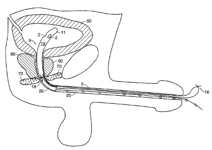
FTGS. 2a-2b illustrate how the embodiment of FIG. 1 can be used to assist
urinary
voiding. The prosthesis 9 is inserted, through the penile urethra, fiuther up
into the urethra of a
patient, until the distal portion 11 of the prostatic segment 10 is disposed
in the bladder 50 where
3o the distal opening 2 can receive urine. Proper positioning of the
prosthesis can be confirmed
through a cystoscope or other means, one of which will be discussed later in
association with
CA 02446914 2003-11-14
WO 02/092158 PCT/US02/13656
-9-
FIGS. 3-4. Once properly positioned, a portion of the prostatic segment 10
should be inside the
prostatic urethra, which is adjacent to a prostate 60. The connection between
the prostatic
segment 10 and the bulbar segment 20 should be adjacent to an external urinary
sphincter 70.
When normal sphincter function is compromised, such as when the patient is
under anesthesia,
the inter-segmental distance 4 between segments 10 and 20 is shortened,
through ways described
in association with FIG. 1. As particularly shown in FIG. 2a, the adjustable
tie 5 connects the
first and second segments 10 and 20 of the prosthesis 9 in two loops, as the
two ends of the tie 5
are connected at a knot 16. Upon pulling the knot 16 substantially away from
the first segment
10, the smaller loop formed by tie 5 gets tightened, bringing the two segments
close enough to
to allow constant fluid communication between their lumens. Under this compact
configuration,
the prosthesis holds the urethra and the external sphincter muscles 70 open,
thereby providing
constant urine drainage through the aligned hunens.
When the patient regains voluntary control over the external sphincter 70,
such as when
the effects of anesthesia wears off, an extended configuration of the
prosthesis may be used to
i5 allow voluntary control over urine voiding. As shown in FIG. 2b, the inter-
segmental distance 4
between the prostatic segment 10 and bulbar segment 20 is lengthened, allowing
the insertion of
the external sphincter 70. If the prosthesis 9 is in the compact configuration
depicted in FIG. 2a,
an operator may transform the prosthesis 9 into an extended configuration by
increasing the
distance between the segments 10 and 20. The operator may pull the retrieval
piece 25, attached
2o to the proximal portion of the bulbar segment 20, substantially away from
the prostatic segment
10, until stopped by the second tie 18. In this case, the inter-segmental
distance 4 increases
toward its maximum value set by the second tie 18 that coimects the two
segments. Since the
extended configuration does not rely on the adjustable tie, the adjustable tie
may be cut Loose, if
knotted, and/or removed from the urethra while at least a portion of the
prosthesis 9 remains
25 inside the urethra. The removal can be achieved by simply pulling one loose
end of the
adjustable tie 5 out of the urethra. The rest of the tie S will follow. Under
this extended
configuration, the distance between the prostatic segment 10 and bulbar
segment 20 may be
designed to be long enough for the sphincter muscles 70 to contract between
the two tubular
segments and intercept or block fluid flow between the lumens of the segments
10 and 20.
3o The methods provided here are particularly useful for patients whose
external sphincter
function is temporarily compromised, as in the situation of undergoing an
anesthetic procedure
CA 02446914 2003-11-14
WO 02/092158 PCT/US02/13656
-10-
that affects the sphincter muscles. When the sphincter is under the influence
of anesthesia, the
prosthesis may assume a compact configuration, such as one depicted in FIG.
2a, to provide
constant urine drainage. When the effect of anesthesia is wearing off, the
prosthesis may be
transformed into an extended configuration, such as one depicted in FIG. 2b,
to allow voluntary
control over urine voiding through the external sphincter. There may be a
variety of reasons why
the patient needs the assistance of a urinary prosthesis, such as in the
situation of having enlarged
prostate 60, which obstructs the prostatic urethra. By using a prosthesis
described here, the
patient has the ability to control assisted voiding as soon as his external
sphincter regains its
function.
to A collecting device such as a condom catheter may be placed around the
patient's penis
for receiving drained fluid. Since the bulbar segment typically does not
extend outside the
patient's body, and only the ties and the retrieval piece extend that far, the
risk of infection is
minimized.
FIG. 3 shows some additional features that may be incorporated into various
15 embodiments of the invention. The prostatic segment 10 may include an
inflatable balloon 1
connected through a tube 3 to an inflation source 8 that can introduce fluid
(e.g., air, saline fluid)
into tube 3. The tube 3 may be made of a flexible material. In the particular
embodiment shown
in FIG. 3, the inflation source is a syringe with a checlc valve 22. Once the
balloon 1 is inflated,
the checlc valve 22 (or a one-way valve) ensures that the balloon stay
inflated by stopping fluid
2o from flowing back. Other auxiliary structures, such as a malecot, that can
be enlarged from
outside the patient's body once the prosthesis is inserted into the urethra
are also contemplated to
be useful here.
The balloon or its equivalent structure can be used to confirm proper
placement of the
prosthesis. Referring to FIG. 4, first, the prosthesis is inserted high up the
urethra where the
25 balloon portion most likely enters the bladder 50. Then a volume of fluid
is delivered through
the tube 3 to inflate the balloon 1. And the operator pulls on the retrieval
piece 25 to withdraw
the prosthesis until resistance is felt, meaning that the inflated balloon 1
has been stopped by the
bladder neck 51. The prosthesis is designed so that the portion from the
balloon to the proximal
end of the prostatic segment 10 corresponds to the length of the prostatic
urethra--once the
3o balloon hits the bladder neclc, the connection between the prostatic
segment and the bulbar
CA 02446914 2003-11-14
WO 02/092158 PCT/US02/13656
-11-
segment is substantially adjacent to the sphincter muscles 70. This means of
confirming the
proper placement of a urinary prosthesis does not require the use of a
cystoscope, permitting a
general practitioner or other medical staff to perform this procedure.
A third tubular segment may optionally be attached proximally to the bulbar
segment.
The third segment contains a lumen aligned with the lumen of the bulbar
segment. The third
segment may be removably connected to the bulbar segment (e.g. using an
adjustable tie similar
to the one used to connect the prostatic segment with the bulbar segment). The
third segment
may be long enough to extend outside the patient's body during use. A drainage
bag may be
connected to the proximal portion of the prosthesis (e.g., the proximal
portion of the third
1 o segment) to collect drained fluid.
A further embodiment of the invention is illustrated in FIGS. 5-6. A prostatic
segment 10
and a bulbar segment 20 similar to the ones described earlier are connected by
at least one first
tie 33 and at least one second tie 44. Both ties may be a thread, a ribbon, a
cord, a wire, a tape, a
line or the like, that engages, uutes, links or holds the two prosthetic
segments together. The
first tie 33 engages the two segments by holding them in close proximity to
allow fluid
communication between the lumens of the segments IO and 20. The second tie 44
connects the
two segments with a pre-determined inter-segmental length. In a preferred
embodiment, the first
tie 33 holds the proximal portion 19 of the segment 10 'in direct contact with
the distal portion 21
of the segment 20. The second tie 44 may be fixedly fastened, at both ends, to
the prosthesis, as
2o shown in FIGS. 5-6. Or, as also shown in FIG. 6, the second tie 44 may be a
closed loop
between the segments 10 and 20, and at points 31 and 32 where the second tie
44 engages the
prosthesis, the second tie 44 may be able to slide through the points 31 and
32. If the first tie 33
is disengaged from the prosthesis, as shown in FIG. 6, the segment 10 is
connected to the
segment 20 at a longer inter-segmental distance that is now limited by the
second tie 44.
FIG. 7 illustrates the details of a preferred embodiment of the first tie 33
shown in FIG. 5.
The first tie 33 forms a closed Loop between the prostatic segment 10 and the
bulbar segment 20.
At junction 66, a tape portion 35 of the first tie 33 extends out. The
junction 66 can adopt a
variety of geometric shapes. As shown in FIG. 7, the junction 66 assumes a "T"
shape.
Alternatively, the junction 66 can adopt a "Y" shape or other suitable shapes.
Two perforated
lines travel throughout the length of the tape portion 35, dividing the tape
portion 35 into three
CA 02446914 2003-11-14
WO 02/092158 PCT/US02/13656
-12-
longitudinal sections. A middle section 37 is further connected to an
actuation thread 77 at
junction 66. The actuation thread 77 may be of a length that, once the
prosthesis is properly
positioned inside the patient, the thread 77's end 76, which is opposite the
junction 66, extends
outside the patient's body. When the end 76 of the actuation thread 77 is
pulled with enough
strength, the perforated lines in the tape portion 35 will tear, starting from
junction 66, all the
way along the tape portion 35. Consequently, the middle section 37 is torn
away, effectively
disconnecting the loop formed by the first tie 33. Optionally, the tape
section 35 itself may be
long enough to extend outside the patient's body during use, and once the loop
of the first tie 33
is disconnected at the junction 66 by pulling the actuation thread 77, the
rest of the loop may be
1o removed from the urethra by simply pulling on the rest of the tape section
35.
To drain bodily fluid from a patient, the embodiment illustrated in FIGS. 5-7
is first
inserted into the urethra of a patient. Proper placement may be confirmed, for
example, through
the inflated balloon in the prostatic segment. The prosthesis may be inserted
in a compact
configuration where the prostatic segment 10 and the bulbar segment 20 are
held close enough,
by the first tie 33, to allow fluid communication between the lumens of the
prosthesis. In the
situation where patient is under anesthesia, the compact configuration
provides constant urinary
drainage for the patient. When the effect of anesthesia wears off, and the
patient regains
sphincter function, an operator can pull on the extra-corporeal end 76 of the
actuation thread 77,
disconnecting the first tie 33 at junction 66, as described above in
connection with FIG. 7. Once
2o the first tie 33 is disconnected, the operator may pull on the retrieval
piece 25 connected to the
proximal portion 29 of the bulbar segment 20 to further separate the two
segments into an
extended configuration. The second tie 44 now determines the maximum length of
the inter-
segmental distance, which may be designed to allow the sphincter muscles to
contract between
the two prosthetic segments and to intercept or block fluid communication
between the lumens
of the segments.
The invention contemplates the combination of the prosthesis as described
above with
other auxiliary devices used during treatment or surgical procedure of the
urinary tract such as
treating urinary retention. The use of the prosthesis may be combined with an
insertion sleeve, a
pusher, a stylet, an endoscope, and so on. A pusher may be used to advance the
prosthesis up the
3o urethra and into the bladder. A stylet may reside within the lumens of both
the prostatic segment
CA 02446914 2003-11-14
WO 02/092158 PCT/US02/13656
-13-
and the bulbar segment to maintain the overall connection between the
segments, especially in
the extended configuration.
Variations, modifications, and other implementations of what is described
herein will
occur to those of ordinary slcill in the art without departing from the spirit
and the scope of the
invention as claimed. Accordingly, the invention is to be defined not by the
preceding
illustrative description but instead by the spirit and scope of the following
claims.