Note: Claims are shown in the official language in which they were submitted.
8
CLAIMS
1. A method of controlling rock drilling, the method comprising:
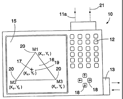
drilling rock with a rock drilling apparatus including a carrier, a feeding
beam, a rock drill movable with respect to the feeding beam, and a control
unit
for controlling the rock drilling, and the rock drilling having adjustable
operating
parameters including at least one of impact power, impact pressure, feed
force,
feed pressure, feed flow, feed rate, rotation torque, rate of rotation,
rotation
pressure, rotation flow, flushing pressure, and flushing flow,
providing a memory of the control unit with default settings for drilling,
measuring an operation of the apparatus during drilling, said operation
comprising at least one said parameter, and
adjusting at least one operating parameter of drilling to accomplish a
desired control operation, said adjusting step including:
providing an operating system of the control unit with at least two
simultaneously active control modes with different control strategies, each
control
mode determining at least one target criterion to be measured during drilling,
said
target criterion comprising the effect of adjusting at least one parameter, a
threshold value for a measurement result of said at least one target
criterion, and
at least one adjustable operating parameter,
prioritizing one control mode over the other control modes such that an
affect of the prioritized control mode increases and simultaneously affects of
the
other control modes diminish, and
calculating, based on the measurement results of said at least one target
9
criterion, control values for the operating parameters to be adjusted in the
control
unit in order to automatically control the drilling such that the control
strategy of
the prioritized control mode is weighted relative to the other control modes.
2. A method according to claim 1, comprising:
providing the control unit with a user interface,
arranging an operating area of the shape of a plane geometrical polygon
in the user interface,
selecting the operating point of the control by moving a control cursor in
the operating area,
placing one control mode in each corner of the operating area, and
calculating a weighting coefficient for each control mode by means of the
distance between the operating point and the corners.
3. A rock drilling apparatus comprising:
a carrier,
a feeding beam,
a rock drill movable with respect to the feeding beam, and
a control system including:
a control unit provided with a user interface for controlling the
drilling,
at least one sensor for measuring drilling operation, said operation
comprising at least one said parameter including at least one of impact power,
impact pressure, feed force, feed pressure, feed flow, feed rate, rotation
torque,
rate of rotation, rotation pressure, rotation flow, flushing pressure, and
flushing
10
flow,
and an operating system for the control unit, wherein the operating
system is provided with at least two simultaneously active preformed control
modes with different control strategies, and wherein each control mode
determines at least one target criterion to be measured during the drilling,
said
target criterion comprising the effect of adjusting at least one parameter, a
threshold value for a measurement result of said at least one target
criterion, and
at least one adjustable operating parameter, wherein one control mode can be
prioritized over the other control modes such that an affect of the
prioritized
control mode increases and simultaneously affects of the other control modes
diminish, and
the control unit is arranged to automatically adjust, based on the
measurement results of said at least one target criterion, the operating
parameters determined by the control modes such that the drilling result
according to the prioritized control mode is weighted over the other control
modes.
4. A rock drilling apparatus according to claim 3,
wherein the user interface of the control unit includes an operating area of
the shape of a plane geometrical polygon,
one control mode is placed in each corner of the polygon,
the user interface includes a control cursor whose location in the operating
area is arranged to represent a currently selected operating point of the
control,
and
11
the control unit is arranged to calculate the weighting of each control mode
depending on the distance from the operating point to the corners of the
polygon.
5. A rock drilling apparatus according to claim 4, wherein the operating
system includes a triangular operating area.
6. A rock drilling apparatus according to claim 5, wherein the first corner of
the triangular operating area is provided with a control mode optimizing the
penetration rate of the drilling,
the second corner of the triangle is provided with a control mode
optimizing the straightness of the hole to be drilled, and the third corner of
the
triangle is provided with a control mode optimizing the service life of the
drilling
equipment.
7. A rock drilling apparatus according to claim 3, wherein the control unit
includes a graphical user interface.
8. A method of controlling rock drilling, the method comprising:
drilling rock with a rock drilling apparatus including a carrier, a feeding
beam, a rock drill movable with respect to the feeding beam, and a control
unit
for controlling the rock drilling,
providing a memory of the control unit with default settings for drilling,
measuring an operation of the apparatus during drilling, said operation
comprising at least one said parameter including at least one of impact power,
impact pressure, feed force, feed pressure, feed flow, feed rate, rotation
torque,
rate of rotation, rotation pressure, rotation flow, flushing pressure, and
flushing
12
flow, and
adjusting at least one operating parameter of drilling to accomplish a
desired control operation, said adjusting step including:
providing an operating system of the control unit with at least two
simultaneously active control modes with different control strategies, each
control
mode determining at least one target criterion to be measured during drilling,
said
target criterion comprising the effect of adjusting at least one parameter, a
threshold value for a measurement result of said at least one target
criterion, and
at least one adjustable operating parameter, the at least two simultaneously
active control modes being at least two of a control mode to optimize a
penetration rate of drilling, a control mode to optimize the straightness of a
drill
hole, a control mode to optimize the service life of drilling equipment, a
control
mode to ease unscrewing threaded connections between drilling components,
and a control mode to minimize vibration occurring in the rock drilling
apparatus,
prioritizing one control mode over the other control modes such that an
affect of the prioritized control mode increases and simultaneously affects of
the
other control modes diminish, and
calculating, based on the measurement results of said at least one target
criterion, control values for the operating parameters to be adjusted in the
control
unit in order to automatically control the drilling such that the control
strategy of
the prioritized control mode is weighted relative to the other control modes.
9. A method of controlling rock drilling, the method comprising:
drilling rock with a rock drilling apparatus including a carrier, a feeding
13
beam, a rock drill movable with respect to the feeding beam, and a control
unit
including a user interface and a memory with default settings for drilling,
controlling the rock drilling with the control unit, including:
arranging an operating area of the shape of a plane geometrical polygon
in the user interface,
selecting the operating point of the control by moving a control cursor in
the operating area,
placing one control mode in each corner of the operating area, and
calculating a weighting coefficient for each control mode by means of the
distance between the operating point and the corners,
measuring an operation of the apparatus during drilling, said operation
comprising at least one said parameter including at least one of impact power,
impact pressure, feed force, feed pressure, feed flow, feed rate, rotation
torque,
rate of rotation, rotation pressure, rotation flow, flushing pressure, and
flushing
flow, and
adjusting at least one operating parameter of drilling to accomplish a
desired control operation, said adjusting step including:
providing an operating system of the control unit with at least two
simultaneously active control modes with different control strategies, each
control
mode determining at least one target criterion to be measured during drilling,
said
target criterion comprising the effect of adjusting at least one parameter, a
threshold value for a measurement result of said at least one target
criterion, and
at least one adjustable operating parameter,
14
prioritizing one control mode over the other control modes, and
calculating, based on the measurement results of said at least one target
criterion, control values for the operating parameters to be adjusted in the
control
unit in order to automatically control the drilling such that the control
strategy of
the prioritized control mode is weighted relative to the other control modes.
10. A control system for a rock drilling apparatus comprising:
a carrier,
a feeding beam,
a rock drill movable with respect to the feeding beam,
at least one sensor for measuring drilling operation, said operation
comprising at least one said parameter including at least one of impact power,
impact pressure, feed force, feed pressure, feed flow, feed rate, rotation
torque,
rate of rotation, rotation pressure, rotation flow, flushing pressure, and
flushing
flow,
a control unit including:
an operating system including at least two simultaneously active
preformed control modes with different control strategies, and wherein each
control mode determines at least one target criterion to be measured during
the
drilling, said target criterion comprising the effect of adjusting at least
one
parameter, a threshold value for a measurement result of said at least one
target
criterion, and at least one adjustable operating parameter, wherein one
control
mode can be prioritized over the other control modes, and
a user interface for controlling the drilling, the user interface including:
15
an operating area of the shape of a plane geometrical polygon,
one control mode is placed in each corner of the polygon,
the user interface includes a control cursor whose location in the operating
area is arranged to represent the currently selected operating point of the
control,
and
the control unit is arranged to calculate the weighting of each control mode
depending on the distance from the operating point to the corners of the
polygon,
wherein the control unit is arranged to automatically adjust, based on the
measurement results of said at least one target criterion, the operating
parameters determined by the control modes such that the drilling result
according to the prioritized control mode is weighted over the other control
modes.
11. A control system according to claim 10, wherein the operating system
includes a triangular operating area.
12. A control system according to claim 11, wherein the first corner of the
triangular operating area is provided with a control mode optimizing the
penetration rate of the drilling,
the second corner of the triangle is provided with a control mode
optimizing the straightness of the hole to be drilled, and
the third corner of the triangle is provided with a control mode optimizing
the service life of the drilling equipment.
16
13. A control system for a rock drilling apparatus comprising:
a carrier,
a feeding beam,
a rock drill movable with respect to the feeding beam,
at least one sensor for measuring drilling operation, said operation
comprising at least one said parameter including at least one of impact power,
impact pressure, feed force, feed pressure, feed flow, feed rate, rotation
torque,
rate of rotation, rotation pressure, rotation flow, flushing pressure, and
flushing
flow,
a control unit including
an operating system including at least two simultaneously active
preformed control modes with different control strategies, and wherein each
control mode determines at least one target criterion to be measured during
the
drilling, said target criterion comprising the effect of adjusting at least
one
parameter, a threshold value for a measurement result of said at least one
target
criterion, and at least one adjustable operating parameter, wherein one
control
mode can be prioritized over the other control modes, and
a user interface for controlling the drilling, the user interface including:
an operating area of the shape of a line segment, two control modes are
arranged at first and second end points of the line segment, and
a control cursor whose location on the line segment is arranged to
represent the currently selected operating point of the control,
wherein the control unit is arranged to calculate the weighting of the two
17
control modes depending on the distance from the operating point to the first
and
second end points of the line segment,
wherein the control unit is arranged to automatically adjust, based on the
measurement results of said at least one target criterion, the operating
parameters determined by the control modes such that the drilling result
according to the prioritized control mode is weighted over the other control
modes.
14. A control system for a rock drilling apparatus comprising:
a carrier,
a feeding beam,
a rock drill movable with respect to the feeding beam,
at least one sensor for measuring drilling operation, said operation
comprising at least one said parameter including at least one of impact power,
impact pressure, feed force, feed pressure, feed flow, feed rate, rotation
torque,
rate of rotation, rotation pressure, rotation flow, flushing pressure, and
flushing
flow,
a control unit including:
a user interface for controlling the drilling,
an operating system including at least two simultaneously active
preformed control modes with different control strategies, the at least two
simultaneously active control modes being at least two of a drilling
efficiency
mode, a quality mode, and a cost mode, and wherein each control mode
determines at least one target criterion to be measured during the drilling,
said
18
target criterion comprising the effect of adjusting at least one parameter, a
threshold value for a measurement result of said at least one target
criterion, and
at least one adjustable operating parameter, wherein one control mode can be
prioritized over the other control modes, and
wherein the control unit is arranged to automatically adjust, based on the
measurement results of said at least one target criterion, the operating
parameters determined by the control modes such that the drilling result
according to the prioritized control mode is weighted over the other control
modes.