Note: Descriptions are shown in the official language in which they were submitted.
CA 02447269 2003-11-13
1
SPECIFICATION
Fuel Battery Device and Method For Controlling Fuel Battery
Technical Field
The present invention relates to a fuel cell apparatus
having an electrolyte disposed between a fuel electrode and
an oxygen electrode , wherein a fuel , such as hydrogen , as well
as air are fed to the fuel cell to generate desired electromotive
force, and a method for controlling the fuel cell.
Background Art
A fuel cell is an apparatus in which an electricity
generator generates electric power by supplying fuel fluid,
such as hydrogen gas or methanol, and a solid polymer type
fuel cell generally has a structure such that a proton conductor
membrane is disposed between an oxygen-side electrode and a
fuel-side electrode. Air is fed to the oxygen-side electrode
for supplying oxygen thereto, and fuel fluid is supplied to
the fuel-side electrode. When the fuel cell generates
electricity, protons move an electrolyte membrane which is
an ion-exchange membrane, and reacts with oxygen on the
oxygen-side electrode to cause a current and form water on
the oxygen-side electrode. The electricity generator portion
of the fuel cell is called electrolyte membrane-electrode
composite or membrane and electrode assembly (MEA) , and a fuel
cell having a plane structure is constituted by the electrolyte
membrane-electrode composite solely or the composites
arranged in a plane, or a fuel cell having a stack structure
is constituted by the composites stacked on one another.
CA 02447269 2003-11-13
2
Recently, in the field of vehicles for transport and the
like, application of the fuel cell to electric car or hybrid
car is intensively expected, and, in addition, the fuel cell
is expected to be put into practical use as a household power
supply system and the like. Further, taking advantage of the
lightweight and small fuel cell, studies and development are
being made on application of the fuel cell to portable apparatus ,
small-size power supply, and the like.
As a fuel cell of one type, there is a fuel cell having
no moistening device for keeping humidity of the electrolyte
membrane or the like (hereinafter, the fuel cell of this type
is referred to as "self-moistening type fuel cell"). The
self-moistening type,fuel cell is constructed so that moisture
formed on the oxygen-side electrode causes the electrolyte
membrane to be wet to promote ion-exchange. In the fuel cell,
control of evaporation of the moisture formed leads to control
of the electricity generation performance of the fuel cell,
and the output voltage directly affects heat generation and
the output current directly affects water formed. Therefore,
it is necessary to operate the self-moistening type fuel cell
so that the electrolyte membrane is appropriately wet by
utilizing formed water, which is directly affected by the
output current , and excess water formed would not block the
feed passage of oxygen.
However, especially in the above-mentioned
self-moistening type fuel cell, when the load current is
decreased or the air feed rate is increased during the operation ,
the electrolyte membrane is reduced in moisture and dried.
In the fuel cell dried, the ion-exchange characteristics of
CA 02447269 2003-11-13
3
the electrolyte membrane become poor, so that the output of
the fuel cell is considerably lowered. In addition, not only
when the load current is decreased during the operation, but
also, for example, when the fuel cell is started again after
the fuel cell is allowed to stand for a long time, the electrolyte
membrane is in a dry state, and it is not easy to let the
electrolyte membrane be wet again after the start, and hence
it takes a period of time as long as several days to recover
the original performance of the fuel cell to obtain a desired
rated output. The problem of drying of the electrolyte
membrane is marked especially in an open-air type fuel cell
in which no compressed air feeding is conducted, and the problem
of drying arises merely if the fuel cell is allowed to stand
after the operation, causing a disadvantage in that the output
characteristics are lowered in a short time.
In view of the above technical problems, an object of
the present invention is to provide a fuel cell apparatus and
a method for controlling a fuel cell, which can prevent the
problems of the low output during the operation or at the start
of operation.
DISCLOSURE OF THE INVENTION
The fuel cell apparatus of the present invention has a
fuel cell having an electricity generator which includes an
oxygen electrode,afuel electrode,and an electrolyte disposed
between the oxygen electrode and the fuel electrode,
characterized in that the fuel cell apparatus has a bypass
circuit for electrically connecting the oxygen electrode and
the fuel electrode to let a current flow if an output voltage
of the fuel cell becomes equal to a first predetermined value
CA 02447269 2003-11-13
4
or less.
In the present invention, the bypass circuit is provided
and therefore, if, for example, the output characteristics
decreases due to drying of the oxygen electrode, the bypass
circuit is operated and controlled to permit a load current
on the fuel cell to vary depending on the output state , making
it possible to intentionally increase the amount of water
formed. The formed water can suppress drying of the oxygen
electrode and also let the oxygen electrode be in an appropriate
wet state. In one embodiment of the present invention, the
first predetermined value is in the range of, for example,
0.01 to 0.8 V per electricity generator, and set to be, for
example, 1 to 95 ~ of a usual electromotive force.
Alternatively, the first predetermined value may be set to
be a value by the amount lowered from the general electromotive
force .
In addition, a fuel cell apparatus of the present invention
is characterized by having: a fuel cell including an
electrolyte disposed between a fuel electrode and an oxygen
electrode,wherein thefuel cell generates electromotiveforce
by feeding a fuel to the fuel electrode and feeding air to
the oxygen electrode; and a load control portion, connected
to the fuel cell, for permitting a load on the fuel cell to
vary depending on the state of output or internal resistance
of the fuel cell.
In the fuel cell, air is fed to the oxygen electrode while
feeding a fuel to the fuel electrode to cause proton conduction
in the electrolyte . The amount of the proton conduction varies
CA 02447269 2003-11-13
. 5
in accordance with the load current connected to the fuel cell,
and, if the load current value is smaller, the output voltage
increases to reduce heat generation and, conversely, if the
load current is larger, the amount of the proton conduction
increases and an amount of formed water increases . The reason
for this is that the reaction on the oxygen electrode is promoted.
For example, if the output characteristics are lowered due
to drying of the oxygen electrode, the load control portion
is operated and controlled to permit a load current on the
fuel cell to vary depending on the output state, making it
possible to intentionally increase the amount of water formed.
The water formed can suppress drying of the oxygen electrode
as well as let the oxygen electrode be in an appropriate wet
state.
Further, a method for controlling a fuel cell of the
present invention is characterized by comprising the steps
of : monitoring output characteristics or internal resistance
characteristics of a fuel cell; and controlling a current
flowing the fuel cell to be larger than usual if the output
characteristicsor internal resistance characteristicsof the
fuel cell change.
In the method for controlling a fuel cell of the present
invention, first, the output characteristics or internal
resistance characteristics of the fuel cell are monitored to
judge whether or not the output characteristics or internal
resistance characteristics of the fuel cell change: If the
output characteristics or internal resistance
characteristics of the fuel cell change, for example, the
output characteristics decreases due to drying of the oxygen
CA 02447269 2003-11-13
6
electrode, the current which flows the fuel cell is controlled
to be larger than usual so as to promote the reaction on the
oxygen electrode, so that the amount of water formed is
increased. Thus, not only can drying of the oxygen electrode
be suppressed, but also the oxygen electrode can be in an
appropriate wet state.
A fuel cell apparatus of the present invention is
characterized by having : a fuel cell comprising an electrolyte
disposed between a fuel.electrode and an oxygen electrode,
wherein the fuel cell generates electromotive force by feeding
a fuel to the fuel electrode and feeding air to the oxygen
electrode; and an air feeding control portion for permitting
a feed rate of air fed to the oxygen electrode of the fuel
cell to vary depending on the state of the output or internal
resistance of the fuel cell.
In the fuel cell, air is fed to the oxygen electrode while
feeding a fuel to the fuel electrode to cause proton conduction
in the electrolyte . The amount of the proton conduction varies
depending on the load current connected to the fuel cell, and,
if the load current becomes larger, the amount of the proton
conduction increases and an increased amount of water is formed.
The feed rate of air fed to the oxygen electrode of the fuel
cell is ideally operated so that, for example, during the
operation, the amount of water formed and the amount of moisture
evaporated which depends on the air feed rate are steadily
in equilibrium, but the air feed rate is changed by the air
feeding control portion and controlled so as to, for example,
suppress evaporation of moisture from the fuel cell surface,
thus making it possible to suppress drying of the oxygen
CA 02447269 2003-11-13
. 7
electrode and let the oxygen electrode be in an appropriate
wet state.
Further, a method for controlling a fuel cell of the
present invention is characterized by comprising the steps
of: monitoring output characteristics or internal resistance
characteristics of a fuel cell; and controlling a feed rate
of air fed to the fuel cell to be smaller than usual if the
output characteristics or internal resistance
characteristics of the fuel cell change.
If the output characteristics or internal resistance
characteristics of the fuel cell change, the feed rate of air
fed to the fuel cell is controlled to be smaller than usual,
and thus , not only can drying of the oxygen electrode in the
fuel cell be suppressed, but also the oxygen electrode can
be in an appropriate wet state, and monitoring the necessity
of this directly from the output characteristics or internal
resistance characteristics of the fuel cell makes it possible
to quickly deal with the matter even if a failure occurs in
the electricity generation. In the present specification,
the measurement of electromotive force encompasses
measurements and calculations of an output current and an
internal resistance of the fuel cell or similar parameters.
BRIEF DESCRIPTION OF THE DRAWINGS
Fig. 1 is a block diagram showing a fuel cell apparatus
according to one embodiment of the present invention.
Fig. 2 is a time chart showing the output voltage of the
fuel cell apparatus according to the above one embodiment.
Fig. 3 is a diagrammatic perspective view showing a fuel
CA 02447269 2003-11-13
8
cell apparatus according to an embodiment of the present
invention.
Fig. 4 is a perspective view showing that a fuel cell
card according to an embodiment of the present invention is
inserted to a laptop personal computer.
Fig. 5 is a perspective view showing the appearance of
the fuel cell card of Fig. 4.
Fig. 6 is a diagrammatic view showing an essential part
of the fuel cell main body of a fuel cell apparatus according
to an embodiment of the present invention.
Fig. 7 is a block diagram showing a fuel cell apparatus
according to the second embodiment of the present invention.
Fig. 8 is a time chart for explaining the operation of
the fuel cell apparatus of Fig. 7.
Fig. 9 is a flowchart for explaining the operation of
the fuel cell apparatus of Fig. 7.
Fig. 10 is a block diagram showing a fuel cell apparatus
according to the third embodiment of the present invention.
Fig. 11 is a block diagram showing a fuel cell apparatus
according to the fourth embodiment of the present invention.
Fig. 12 is a time chart showing the output voltage of
the fuel cell apparatus according to the fourth embodiment.
Fig. 13 is a block diagram showing a fuel cell apparatus
according to the fifth embodiment of the present invention.
Fig. 14 is a time chart for explaining the operation of
the fuel cell apparatus of Fig. 13.
Fig. 15 is a flowchart for explaining the operation of
the fuel cell apparatus of Fig. 13.
Fig. 16 is a block diagram showing a fuel cell apparatus
according to the sixth embodiment of the present invention.
Fig. 17 is a block diagram showing a fuel cell apparatus
CA 02447269 2003-11-13
9
according to the seventh embodiment of the present invention.
Fig . 18 is a block diagram showing a fuel cell apparatus
according to the eighth embodiment of the present invention.
BEST MODE FOR CARRYING OUT THE INVENTION
First embodiment
A preferred embodiment of a fuel cell apparatus of the
present invention will be described with reference to the
drawings. Fig. 1 is a block diagram showing a fuel cell
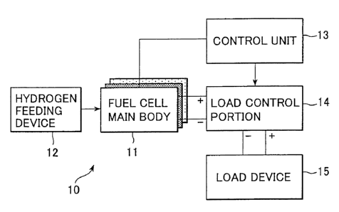
apparatus according to the present embodiment . A fuel cell
apparatus 10 of the present embodiment has a fuel cell main
body 11 for generating electromotive force, a control unit
13 for controlling a load, and a load control portion I4,
connected to the fuel cell main body 11, for permitting a value
of a load on the fuel cell main body 11 to vary. Electromotive
force is generally supplied to a load device 15 through the
load control portion 14, and a hydrogen feeding device 12 for
feeding fuel fluid is connected to the fuel cell main body
11.
The fuel cell main body 11 has a structure described below
as an example such that an electrolyte membrane in a
substantially flat plate form is disposed between a fuel-side
electrode (fuel electrode) and an oxygen-side electrode
( oxygen electrode ) , and fuel fluid, such as hydrogen gas or
methanol, is fed to the fuel-side electrode from the hydrogen
feeding device 12 having a hydrogen storage function. The
oxygen-side electrode is an electrode for drawing oxygen
contained in air, and it faces the fuel-side electrode through
the electrolyte membrane. The oxygen-side electrode may be
CA 02447269 2003-11-13
~ 1~
of an open-air type, and may have a structure to which air
is fed by means of a compressor, a pump, or a fan. The fuel
cell main body 11 may be either in a stack laminate form obtained
by stacking on one another a plurality of structures, each
of which includes the electrolyte membrane in a substantially
flat plate form disposed between the fuel-side electrode and
the oxygen-side electrode, or in a flat plate form consisting
of one structure or two structures stacked.
The hydrogen-feeding device 12 is a device for feeding
fuel fluid, such as hydrogen gas or methanol, to the fuel cell
main body 11 and, as an example, a hydrogen high-pressure tank
or a cartridge containing an alloy having hydrogen absorbed
therein may be used. The hydrogen feeding device 12 may be
detachable from the fuel cell main body 11 as mentioned below,
and may be of a structure such that transmission and reception
of information about the fuel conditions are conducted at a
joint portion.
The control unit 13 is a controller for controlling the
fuel cell apparatus 10, and it monitors the state of the output
or internal resistance of the fuel cell in the fuel cell main
body 11 and outputs signals for controlling in accordance with
the state of the output or internal resistance to the load
control portion 14. The control unit 13 consists of desired
electronic circuits, CPU (central processing unit), and the
like . The control unit 13 and the fuel cell main body 11 do
not necessarily be unified, but may be individually fitted,
or part of the data processing unit of an electronic appliance
having the fuel cell main body 11 mounted may be utilized.
In the present embodiment , the control unit 13 monitors the
CA 02447269 2003-11-13
11
output voltage or internal resistance value of the fuel cell.
However, the monitoring is not limited to this, and the output
current may be monitored or the conditions including a
temperature, a humidity, and an atmospheric pressure may also
be monitored simultaneously.
The load control portion 14 is a bypass circuit for
permitting a load on the fuel cell main body 11 to vary depending
on the state of the output or internal resistance of the fuel
cell main body 11, and, in order to let the fuel cell main
body 11 be in an overcurrent state, a switch element may be
disposed between the output terminals of the fuel cell main
body 11 to cause short-circuiting so that the switch element
is in an ON-state. Alternatively, in order to let the fuel
cell main body 11 be in an overcurrent state, the output
terminals of the fuel cell main body 11 may be connected by
a low-resistance element. The load control portion 14 may
be of a s tructure such that a primary current of a DC-DC converter
or the like is in an overcurrent state as mentioned below.
When the fuel cell main body 11 is in an overcurrent state ,
the output voltage of the fuel cell main body 11 rapidly lowers .
Therefore , as a compensating means for making up for the lowered
output voltage, e.g., a floating battery or a capacitor may
be provided in the subsequent load device 15.
The load device 15 is a device to which the electromotive
force generated in the fuel cell apparatus 10 is fed, and,
when an apparatus onto which the fuel cell apparatus 10 is
mounted is, for example, a personal computer, the fuel cell
apparatus 10 is used as a power supply for the personal computer,
and therefore the load device 15 corresponds to an internal
CA 02447269 2003-11-13
12
circuit or a peripheral device . On the other hand , when the
fuel cell apparatus 10 is mounted on a transport machine , such
as an automobile, the load device corresponds to a device for
causing thrust force, such as a motor. Further, if the fuel
cell apparatus 10 is used as a household small-size power supply ,
an electric bulb or a household electric appliance corresponds
to the load device.
Next , one example of the operation of the load control
portion 14 will be described with reference to Fig. 2. In
Fig. 2, an output voltage Vout of the fuel cell main body,
in which the air feed rate and the load current are constant,
is taken as the ordinate, and a time t is taken as the abscissa.
In the fuel cell apparatus 10 of Fig. 1, the voltage Vout is
maintained at a relatively large value at first, but, as the
operation continues, drying of the electrode on the surface
of the fuel cell main body 11 may be promoted due to the operation
environment . As a result , the output voltage Vout of the fuel
cell main body 11 gradually decreases and becomes lower than
a threshold voltage Vth at a point in time to . The threshold
voltage Vth is a reference level indicating that the output
of the fuel cell in the fuel cell main body 11 becomes low.
If it is recognized that the output voltage Vout of the fuel
cell main body 11 is lower than the threshold voltage Vth on
the control unit 13 side, the control unit 13 detects that
the output of the fuel cell in the fuel cell main body 11 is
low, and an operation for recovery of the function is performed.
Specifically, a signal is transmitted from the control unit
13 to the load control portion 14 to, for example, let the
load control portion 14 be in a low-resistance state.
CA 02447269 2003-11-13
13
By letting the load control portion 14 be in a
low-resistance state, an overcurrent flows the fuel cell main
body 11, so that the dried surface of the fuel cell main body
11 can be in a wet state in a short time. When an overcurrent
flows , the load electric power of the output means is smaller
as viewed from the fuel cell side and therefore the output
voltage becomes small, but a large amount of a current flows
in turn , and thus drawing of oxygen atoms by ion-exchange is
activated to cause moisture in a large amount to form. For
this reason, the surface of the fuel cell main body 11 can
be in a wet state in an extremely short time. While the load
control portion 14 is in a low-resistance state as mentioned
above, electric power supply to the subsequent load device
is unsatisfactory as it is. However, temporary use of an
15 electric power compensating means, such as a floating battery
or a capacitor, provided in the load control portion 14 can
prevent the load device 15 from suffering interruption of the
electric power supply.
When the load control portion 14 is in a low-resistance
state, the output voltage Vout of the fuel cell main body 11
rapidly decreases , and the output voltage Vout becomes lower
than a voltage Vs at a point in time t1 in Fig. 2, so that
the lowering of the output voltage Vout to this point is detected
by the control unit 13 side . As a result , the control unit
l3transmitssignalsfor terminatingthe operationfor recovery
of the function of the fuel cell to the load control portion
14. According to the signals, the load control portion 14
changes the circuit state from the low-resistance state to
a general state.
CA 02447269 2003-11-13
14
As a parameter for detecting the dry state of the fuel
cell main body 11, instead of the above-mentioned output
voltage Vout of the fuel cell main body when the air feed rate
and the load current are constant , an internal resistance value
r may be used in accordance with, for example, a current
interrupt method. In this case, if the internal resistance
value r exceeds a certain value, similar control to the one
described above causes an overcurrent to flow the fuel cell
main body 11, enabling the dried surface of the fuel cell main
body 11 to be in a wet state in a short time. In this case,
the control unit 13 corresponds to an output characteristics
or internal resistance characteristics monitoring means for
monitoring the output characteristics or internal resistance
characteristics of the fuel cell.
Thus, in the fuel cell apparatus 10 of the present
embodiment , the control is made in such a way that the fuel
cell main body 11 becomes in an overcurrent state if the output
voltage Vout from the fuel cell main body 11 decreases to the
threshold voltage Vth or less ( or the internal resistance value
increases to the internal resistance value rth or more) , and
this control forcibly and temporarily recovers the moisture
retaining state of the electrode. For this reason, even if
a rated output voltage cannot be obtained due to unsatisfactory
moisture on the surface of the fuel cell main body 11 during
a long operation or at the start of operation, the output
characteristics of the fuel cell can be recovered in a
relatively short time . In addition, in the fuel cell apparatus
10 of the present embodiment , while the fuel cell main body
11 is controlled to be in an overcurrent state, temporary use
of an electric power compensating means, such as a floating
CA 02447269 2003-11-13
battery or a capacitor, provided in the load control portion
14 can prevent the load device 15 from suffering interruption
of the electric power supply.
5 Fig . 3 shows an example of a fuel cell apparatus in which
airflow means using fans are formed on one sidewall. A
substantially rectangular card-form housing 21 is provided,
and in the housing 21 is placed an electricity generator portion
23. Here, the size of the housing 21 for card-form fuel cell
10 may be a size standardized as PC card as an example, and,
specifically, a size standardized by JEIDA/PCMCIA may be
applied. A standardized size is such that one side (long side)
is 85 . 610 . 2 mm and another side ( short side ) is 54 . 0t0 .1 mm.
The thickness of a card is specified individually with respect
15 to type I and type II. Specifically, with respect to type
I, the thickness of a connector portion is 3.310.1 mm, and
the thickness of a base portion is 3.310.2 mm. With respect
to type II, the thickness of a connector portion is 3.310.1
mm, and the thickness of a base portion is 5.0 mm or less and
10.2 mm of the standard dimension of the thickness. The
card-form housing 21 may be constructed by stacking an upper
housing on a lower housing.
To the card-formhousing 21 is connected ahydrogen storage
cartridge 22 having substantially the same size as that of
the housing in the plane perpendicular to the longitudinal
direction of the card-form housing 21 and being capable of
being continuously attached to the housing. In the hydrogen
storage cartridge 22 is disposed, e.g., a hydrogen storage
portion, such as an alloy having hydrogen absorbed therein,
and it is detachable from the housing 21 for fuel cell. The
CA 02447269 2003-11-13
. , 16
hydrogen storage cartridge 22 has a mechanism such that , if
being attached, the outlet for fuel is connected to the
connector portion to enable the fuel fluid to flow, and, if
the hydrogen storage cartridge 22 is detached, the fuel flow
from the hydrogen storage cartridge 22 is stopped.
The card-form housing 21 has therein an electricity
generating portion 23 comprising four electricity generators
combined, a connector portion 24 for introducing the fuel fluid
from the hydrogen storage cartridge 22 into the card-form
housing 21, an electricity generation-side connector portion
25 for connection to which the connector portion 24 is inserted,
a flow control portion 27 connected to the electricity
generation-side connector portion 25 through a pipe 26 , a pipe
28 for connecting the flow control portion 27 to the electricity
generating portion 23 , a control circuit portion 29 comprising
electronic parts 30 mounted on a wiring board 31, for conducting
output control and the like using the electronic parts.
Further, in the card-form housing 21, a pair of fans 32, 33
as airflow means are disposed so as to extend along the sidewall
of the housing. The fans 32, 33 are driven by, respectively,
motors 34, 35, so as to rotate. The fan 32 and the fan 33
are disposed in parallel, especially in the present embodiment ,
the fan 32 and the fan 33 are disposed in parallel in the vertical
direction, and they feed air, respectively, to the upper
electricity generator and to the lower electricity generator.
The fans 32, 33 individually have a structure consisting
of blade portions provided on the periphery of a cylindrical
rotating shaft , and each blade portion is formed so that it
extends linearly in the direction of the rotating shaft and
CA 02447269 2003-11-13
17
radially in the direction of the diameter of the rotating shaft .
Therefore, the fans 32, 33 rotate around the rotating shaft
as a center by driving of the motors 34, 35 to feed air to
a space in the housing along not shown grooves in a direction
perpendicular to the rotating shaft. The fans 32, 33 may be
used for evaporation of water formed on the oxygen-side
electrode as mentioned below, and may be used for heat
dissipation by feeding air. The fans 32, 33 are connected
to the motors 34, 35, respectively, through connectors 36,
37, but the motors 34, 35 may be directly connected,
respectively, to the fans 32 , 33 without providing connectors
36, 37.
The electricity generating portion 23 is a structure
consisting of four electricity generators combined, and each
electricity generator hasastructure including an electrolyte
membrane,e.g.,a proton conductor disposedbetween afuel-side
electrode and an oxygen-side electrode, and each of the
oxygen-side electrode and the fuel-side electrode consists
of a conductive material , such as a metallic plate , a porous
metallic material, or a carbon material, and a current
collector is connected to the oxygen-side electrode and the
fuel-side electrode. The current collector is an electrode
material for taking out electromotive force generated in the
electrode, and it is constituted using a metallic material,
a carbon material, or nonwoven fabric having conductivity.
In the four electricity generators, two sets of two stacked
electricity generators are arranged in the housing. When two
electricity generators are stacked on one another, they may
be stacked so that the surfaces of the fuel-side electrodes
face to each other and, in this case, fuel fluid is fed to
CA 02447269 2003-11-13
I8
a space between the fuel-side electrodes stacked to enable
the electrodes to be activated, and the surfaces which require
feeding of oxygen are the oxygen-side electrode surfaces on
the surface and back surface of the electricity generators
stacked.
The electricity generation-side connector portion 25 is
a mechanism portion connected to the connector portion 24 for
the hydrogen storage cartridge 22, for introducing fuel fluid
into the fuel cell while maintaining the airtightness of the
hydrogenstorage cartridge 22. Specifically, the electricity
generation-side connector portion 25 has a mechanism such that
the tip of the connector portion 24 is inserted to the
electricity generation-side connector portion 25 and further
insertion locks the connector portion to prevent gas leakage
during the fitting operation. In a direct methanol system
such that the fuel fluid is not hydrogen gas but liquid, a
detachable fuel fluid storage tank may be used instead of the
hydrogen storage cartridge 22.
A mechanical flow control mechanism may be provided in
the electricity generation-side connector portion 25, but,
in the fuel cell of the present embodiment, the flow control
portion27isdisposed between the electricity generation-side
connector portion 25 and the electricity generating portion
23. The flow control portion 27 is a device for electrically
or mechanically keeping the f low rate of the fuel fluid constant ,
and it may control the pressure using a valve body provided
or the like.
The control circuit portion 29 is a circuit for controlling
CA 02447269 2003-11-13
19
the electromotive force output from the
electricity-generating portion 23, and, in the example shown
in Fig. 3, the control unit 13 and load control portion 14
having the construction in Fig. 1 are formed. The control
circuit portion 29 further may monitor the state of connection
to the hydrogen storage cartridge 22 which is the fuel feeding
side, and control the output while detecting the state of the
load of something to which the output is supplied, for example,
control the output voltage according to a mode ( a . g . , active
mode, waiting mode, or sleep mode) of the appliance utilizing
the electromotive force.
In addition, a circuit portion for controlling the motors
34 , 35 for driving the fans 32 , 33 may be provided in the control
circuit portion 29. As power supply used for the control
circuit portion 29 , part of the electric power generated in
the electricity-generating portion 23 may be used. A pair
of output terminals 38 , 39 protrude from the control circuit
portion 29, and tips of the output terminals 38, 39 protrude
outward from the card-form housing 21.
In the fuel cell apparatus of the present embodiment having
the above structure, the fans 32, 33 for feeding oxygen to
the fuel cell and for promoting evaporation of water formed
on the surface of the oxygen-side electrode are disposed on
one sidewall of the card-form housing 21. By rotating the
fans 32 , 33 to guide air along not shown grooves , efficient
removal of water formed on the surface of the oxygen-side
electrode can be achieved, making it possible to prevent
lowering of the output voltage.
CA 02447269 2003-11-13
In addition, in the fuel cell apparatus of the present
embodiment , the control circuit portion 29 in which the control
unit 13 and load control portion 14 having the construction
in Fig. 1 are formed is incorporated to the same card-form
5 housing 21, and therefore optimization of the output voltage
and control according to the conditions or environment can
be easily practiced. Further, the fuel cell apparatus of the
present embodiment is not only merely an electricity generation
device but also a useful battery having a data processing
10 function. Furthermore, the fuel cell apparatus has a
structure such that an occurrence of fluid leakage, such as
gas leakage , is prevented at the connector portion , and hence
safety of the device is satisfactory.
15 Next, an example of a fuel cell apparatus of an open-air
type will be described with reference to Figs . 4 and 5 . The
fuel cell apparatus of the present invention may be, as one
example, a fuel cell card 40 of a flat plate type having a
card form, and the fuel cell card 40 may be, as shown in Fig.
20 4 , attached to a laptop personal computer ( PC ) 41, which is
an apparatus main body, by inserting through a slot 42 for
card. Here, the slot 42 may be either a hole which is exclusive
to the fuel cell card 40 and formed in the housing of the
apparatus main body or a slot having a size standardized by
JEIDA/PCMCIA. Specifically, a size standardized by
JEIDA/PCMCI is such that one side ( long side ) is 85 . 610 . 2 mm
and another side (short side) is 54.010.1 mm. The thickness
of a card is specified individually with respect to type I
and type II. Specifically, with respect to type I, the
thickness of a connector portion is 3.310.1 mm, and the
thickness of a base portion is 3.310.2 mm. With respect to
CA 02447269 2003-11-13
21
type II, the thickness of a connector portion is 3.3~0.1 mm,
and the thickness of a base portion is 5. 0 mm or less and t0.2
mm of the standard dimension of the thickness . A portion having
hydrogen absorbed therein (hydrogen absorption portion) 44
as a portion for feeding a fuel is detachable from the fuel
cell card 40.
In Fig. 4, the slot 42 is formed in the sidewall portion
of the keyboard-side main body of the laptop PC 41 which is
an apparatus main body. Alternatively, a portion in which
the slot 42 is formed may be part of a selectable bay 43 indicated
by a broken line in Fig. 4. The selectable bay 43 consists
of a plurality of functional members detachable from the laptop
PC 41. When the extended function of the personal computer
is changed, the members incorporated into the selectable bay
43 are exchanged. When using the fuel cell card 40, an
exclusive adopter may be externally attached, or a plurality
of fuel cell cards 40 may be simultaneously incorporated into
a data processing apparatus, e.g., laptop PC 41.
Fig. 5 is a perspective view of the fuel cell card 40
assembled, and the fuel cell card 40, which is formed so that
the corner portions are rounded, taking portability into
consideration, has a structure such that an upper housing 46
in a flat plate form is combined with a lower housing 45, and,
in Fig. 5, the upper housing 46 is fixed to the lower housing
4 5 by means of , a . g . , not shown screws . In the upper housing
46, a plurality of rectangular opening portions 47 is formed
as gas inlets for introducing oxygen into the housing.
In this example, each opening portion 47 is a through
CA 02447269 2003-11-13
22
hole in a substantially rectangular form, and two sets of 15
opening portions consisting of 5 columns x 3 rows are formed
side by side, and the upper housing 46 has 30 opening portions
47 in total. The opening portions 47 cause the oxygen-side
electrode to be open to air as described below, and thus
effective drawing of oxygen is realized without any special
air suction apparatus, simultaneously with removal of excess
moisture.
In the present embodiment , the form of the opening portions
47 is the same as the lattice pattern corresponding to the
lattice form of the pattern of the current collectors.
Alternatively, it may be other forms, and the form of the
individual opening portions may be various forms , such as a
circular form, an elliptic form, a stripe form, and a polygonal
form. Further, in this example, the opening portions 47 are
formed by cutting out the upper housing 46 in a plate form,
and, for preventing contaminant or dust from entering or
depositing so that the oxygen-side electrode can be surely
open to air, net or nonwoven fabric may be provided on the
opening portions 47 . In the lower housing 45 , opening portions
corresponding to the opening portions 47 in the upper housing
46 are formed, and their forms are similar and net or nonwoven
fabric may be similarly provided.
The hydrogen absorption portion 44 capable of supplying
hydrogen is connected to the fuel cell card 40 by fitting a
pair of pins 48 formed on the connection-side sidewall of the
hydrogen absorption portion 44 into a pair of fitting holes
50 formed in the connection-side sidewall of the lower housing
45. In this instance, a protrusion portion 49 which is a
CA 02447269 2003-11-13
~ , 23
hydrogen feeding inlet of the hydrogen absorption portion 44
is inserted to a rectangular fitting hole 51 formed in the
connection-sidesidewall of the lowerhousing45, and connected
to the end portion of a not shown fuel pipe portion extending
to the position of the fitting hole 51 in the housing. The
hydrogen absorption portion 44 is detachable from the fuel
cell card 40, and, for example, when the amount of hydrogen
stored in the hydrogen absorption portion 44 is small, the
hydrogen absorption portion 44 is detached from the fuel cell
card 40 and replaced by another hydrogen absorption portion
44 having satisfactory hydrogen stored therein, or the detached
hydrogen absorption portion 44 may be reused by injecting
hydrogen thereinto. In this example, the pins 48 of the
hydrogen absorption portion 44 are fitted into the fitting
hole 51 to attach the hydrogen absorption portion 44 to the
fuel cell card 40 , but other connection elements may be used
and, for example, a structure using insertion to a key groove
or a structure using a sliding member which slides against
a spring or using a magnet may be employed.
Fig. 6 is a diagrammatic view showing one example of the
fuel cell main body portion. Fig. 6 shows that two electrolyte
membrane-electrode composites i.e., MEAs (membrane and
electrode assemblies) 67, 68 are stacked, and fuel-side
electrodes 63, 64 and oxygen-side electrodes 65, 66 are formed
so that proton conductor membranes 61, 62, which are
ion-exchange membranes,are individually disposed between the
respective electrodes. In the fuel-side electrodes 63, 64
and the oxygen-side electrodes 65, 66, a catalyst material,
such as platinum, is formed, and further not shown current
collectors for taking out charges are formed. A pair of
CA 02447269 2003-11-13
24
fuel-side electrodes 63, 64 faces to each other so that they
have a desired space between them for introducing hydrogen
or the like as a fuel.
Fuel fluid, such as hydrogen gas, is fed from the outside
to the fuel-side electrodes 63, 64, and the fuel fluid reaches
a reaction region through small holes in the electrodes , and
is adsorbed on a catalyst present in the electrodes to form
active hydrogen atoms. The hydrogen atoms become hydrogen
ions and move to the oxygen-side electrode which is the counter
electrode, and feed electrons formed upon ionization to the
fuel-side electrodes 63 , 64 , and the electrons as electromotive
force move through a circuit connected to the outside and then
reach the oxygen-side electrodes 65, 66.
Each of the oxygen-side electrodes 65, 66 and fuel-side
electrodes 63, 64 consists of a conductive material, such as
a metallic plate, a porous metallic material, or a carbon
material, and a current collector is connected to the
oxygen-side electrodes 65, 66 and the fuel-side electrodes
63, 64. The current collector is an electrode material for
taking out electromotive force generated in the electrode,
and it is constituted using a metallic material, a carbon
material, or nonwoven fabric having conductivity. In the
present embodiment, the two MEAs 67, 68 are stacked so that
the fuel-side electrodes 63, 64 are positioned inside, and
thus the oxygen-side electrodes 65, 66 are respectively
positioned on the surface and back surface of the stacked two
MEAs 67, 68. As one example, when using a card-form housing,
the MEAs 67 , 68 may be individually formed in a substantially
rectangularflat plateform of which the longitudinal direction
CA 02447269 2003-11-13
, 25
corresponds to the direction of the long side , but they may
be in other forms. In addition, the structure of the MEAs
67, 68 is not limited to one including two MEAs stacked, but
4, 6, 8, or more MEAs may be combined. Further, when the
individual MEAs have the same form, the same MEAs may be mounted
in the fabrication, but it is not limited to this and MEAs
having different forms may be combined. For example, an MEA
having a larger size and an MEA having a smaller size may be
disposed on the same surface , or an MEAhaving a larger thickness
and an MEA having a smaller thickness may be disposed on the
same surface. Alternatively, for achieving excellent
capacity or efficiency, different types of MEAs having
different performance may be mounted in combination in the
housing. Further, in the present embodiment, the MEAs 67,
68 disposed in the housing have desired stiffness, and each
MEA may have flexibility, and in this case, the housing may
be constituted by a material having flexibility. In addition,
a structure may be such that the MEA itself is of a desired
cartridge type and replaceable. Further, an MEA is shifted,
for example, an MEA is slid in the housing and shifted to change
the conditions of connection between the MEAs.
Second embodiment
Next, a more detailed embodiment of a fuel cell apparatus
of the present invention will be described with reference to
Figs. 7 to 10. First, the fuel cell apparatus according to
the present embodiment has , as shown in Fig . 7 , a fuel cell
main body 71 having a structure formed by stacking on one another
a plurality of electricity generators , a . g . , MEAs , and further
has a control unit 73 for controlling a load and, as a load
control portion, connected to the fuel cell main body 71, for
CA 02447269 2003-11-13
26
permitting the value of a load on the fuel cell main body 71
to vary, a resistance lowering circuit portion including a
switching element 78 and a resistance element 77 , and a power
supply compensating circuit portion including a diode 79 and
a floating battery 80. To the fuel cell main body 71 is
connected through the load control portion a load device 75
to which the electromotive force generated in the fuel cell
main body 71 is fed, and further, to the fuel cell main body
71 is connected a hydrogen feeding device 72 for feeding fuel
fluid. In addition, to the fuel cell main body 71 is connected
an air feeding compressor 76 for feeding air and evaporating
excess moisture.
The fuel cell main body 71 is, as mentioned above, formed
by stacking on one another MEAs each including an electrolyte
membrane disposed between a fuel-side electrode and an
oxygen-side electrode, and hydrogen is fed to the fuel-side
electrode and air is fed to the oxygen-side electrode to
generate electromotive force between a pair of output terminals .
Fuel fluid, such as hydrogen, is fed to the fuel cell main
body 71 from the hydrogen-feeding device 72 via a gas feeding
passage 81, and the fuel fluid is fed to the fuel-side electrode
of the fuel cell main body 71.
The air feeding compressor 76 is a device which changes
an atmospheric pressure , a . g . , a f an or a pump , and it is a
device for feeding oxygen contained in air to the surface of
the oxygen-side electrode of the fuel cell main body 71 and
for feeding air to evaporate moisture generated on the surface
of the oxygen-side electrode. The air feeding compressor 76
and the fuel cell main body 71 may either unify or be detachable
CA 02447269 2003-11-13
27
from each other as individual members. The air feeding
compressor 76 is connected to the fuel cell main body 71 through
an air feeding pipe 82 , and near the outlet of the air feeding
pipe 82 is located the oxygen-side electrode of the fuel cell
main body 71. When the oxygen-side electrode is covered with
water, the electrode cannot draw oxygen any more, so that the
electricity generation characteristics become poor. However,
by virtue of the air-feeding compressor 76 provided,
unnecessary moisture is evaporated and removed. Therefore,
a problem that excess moisture on the oxygen-side electrode
lowers the output is prevented. In addition, in the fuel cell
main body 71, at the start of operation or during a long operation ,
there is a concern that the fuel cell main body 71 is
disadvantageously dried and the efficiency of ion-exchange
in the electrolyte membrane is decreased. However, in the
fuel cell apparatus of the present embodiment , it is possible
to temporarily allow an overcurrent to flow the fuel cell main
body 71, and hence a problem of the dry state of the fuel cell
main body 71 can be solved. Air fed to the fuel cell main
body 71 is exhausted from the fuel cell main body 71 via an
air exhaust pipe 83.
The load device 75 is a device to which the electromotive
force generated in the fuel cell apparatus is fed, and, if
an apparatus onto which the fuel cell apparatus is mounted
is, for example, a personal computer, the fuel cell apparatus
is used as a power supply for the personal computer, and
therefore the load device 75 corresponds to an internal circuit
or a peripheral device. On the other hand, if the fuel cell
apparatus is mounted on a transport machine, such as an
automobile , the load device corresponds to a device for causing
CA 02447269 2003-11-13
. 28
thrust force, such as a motor. Further, if the fuel cell
apparatus is used as a household small-size power supply, an
electric bulb or a household electric appliance corresponds
to the load device 75.
In Fig. 7, the control unit 73 is a device for controlling
the below-described resistance lowering circuit portion and
power supply compensating circuit portion in the load control
portion while monitoring the state of the output or internal
resistance of the fuel cell main body 71. The state of the
output or internal resistance of the fuel cell main body 71
is monitored by information as signals from the output terminal
of the fuel cell, i.e., MEA. In the apparatus of Fig. 7, a
method of monitoring the state of the output or internal
resistance of the fuel cell main body 71 is employed, but the
monitoring method is not limited to this , and the wet degree
of each electrode or electrolyte membrane may be directly
monitored or a temperature or atmospheric pressure sensor may
be used or an output sensor may also be used.
In the present embodiment , the control unit 73 may monitor
the operating conditions of the air-feeding compressor 76 or
control the action of the air-feeding compressor 76. When
controlling the action of the air-feeding compressor 76, by
stopping the action of the air-feeding compressor 76 while
an overcurrent flows the fuel cell main body 71 to form moisture
and recover the electricity generation function, evaporation
of moisture may be avoided . In addition, by stopping the action
of the air-feeding compressor 76, water formed may rapidly
penetrate the electrolyte membrane, thus making it possible
to quickly recover the electricity generation performance.
CA 02447269 2003-11-13
29
Further, the control unit 73 receives information about the
electric power consumption state or electric power required
in the load device 75 , and it can realize electricity generation
at high efficiency according to the information.
The fuel cell apparatus of the present embodiment has,
as a load control portion for permitting the value of a load
current on the fuel cell main body 71 to vary, the resistance
lowering circuit portion including the switching element 78
and the resistance element 77, and the power supply
compensating circuit portion including the diode 79 and the
floating battery 80. The switching element 78 and the
resistance element 77 constituting the resistance lowering
circuit portion are circuits which act according to signals
from the control unit 73, and, for example, as the switching
element 78 , a semiconductor device in the present embodiment ,
such as an insulated gate bipolar transistor ( IGBT) , or a relay
or the like may be used. The resistance element 77 has an
extremely small resistance value, as compared to the load
device 75, and a potential difference generated between the
terminals of the element when a current flows has a small value.
The switching element 78 and the resistance element 77 are
connected in series between a plus terminal and aminus terminal
of the output terminals of the fuel cell main body 71, and,
when the gate electrode of the switching element 78 is
controlled to be on-side, the switching element 78 is in a
conduction state, so that the load current on the output
terminals of the fuel cell main body 71 increases.
The power supply compensating circuit portion in the load
control portion has the diode 79 and the floating battery 80,
CA 02447269 2003-11-13
and the diode 79 serves as a rectifier when the output of the
fuel cell main body 71 is decreased. The floating battery
80 is an element which serves as a power supply for the load
device 75 instead of the fuel cell main body 71 a.f in-between
5 a plus terminal and a minus terminal of the output terminals
of the fuel cell main body 71 is lowered in resistance according
to the action of the resistance lowering circuit portion
including the switching element 78 and the resistance element
77. The plus terminal of the floating battery 80 is connected
10 to the plus terminal of the output terminal of the fuel cell
main body 71 through the diode 79 and connected to the plus
terminal side of the load device 75, and the minus terminal
of the floating battery 80 is connected to the minus terminal
of the output terminal of the fuel cell main body 71 and connected
15 to the minus terminal side of the load device 75 . The floating
battery 80 drives the load device 75 by its electromotive force
when the switching element 78 is in an on-state. Instead of
the floating battery 80, a capacitor or the like may be used.
20 Fig . 8 is one example of a time chart for explaining the
operation of the fuel cell apparatus of Fig. 7, and it is an
example in which an output voltage when the air feed rate and
the load current of the fuel cell are constant is detected
as a parameter of the dry state. A time t is taken as the
25 abscissa, and a cell current i~ell or a cell voltage V~el when
the load current is constant is taken as the ordinate. The
cell voltage V~ell corresponds to the output voltage Vout of
the fuel cell main body 71. In this fuel cell apparatus , when
lowering of the output voltage of the fuel cell main body 71
30 becomes remarkable, the control unit 73 detects the lowering
of the output voltage. If it is recognized that the output
CA 02447269 2003-11-13
31
voltage is not higher than a certain value (Vth in Fig. 2,
for example), the switching element 78 is controlled to be
in a conduction state according to signals from the control
unit 73, so that the resistance lowering circuit portion
including the switching element 78 and the resistance element
77 is changed from a general load state or a non- conduction
state to a low-resistance state. Then, the fuel cell main
body 71 is in a state such that a resistance between the output
terminals is lowered or short-circuiting occurs between the
output terminals, so that a large cell current i~ell~ i.e.~
an overcurrent flows the fuel cell main body 71. The
overcurrent which f lows the fuel cell main body 71 causes oxygen
atoms to vigorously bond to hydrogen atoms on the oxygen-side
electrode to form water in a large amount temporarily, and,
if the output is decreased due to drying, the electrolyte
membrane is rapidly in a wet state , making it possible to quickly
recover the output.
When an overcurrent flows the fuel cell main body 71,
a potential difference between the output terminals, i.e..
cell voltage V~ell rapidly becomes smaller . Therefore , as shown
in Fig. 8, the voltage becomes lower than a predetermined
voltage (voltage Vs in Fig. 2, for example) in a relatively
short time, and the control unit 73 detects the fact that the
output voltage is lower than a predetermined voltage , letting
the switching element 78 be in an off-state . Then ~ the circuit
state of the load control portion changes to a general state,
so that the current passage via the switching element 78 and
the resistance element 77 is shut out. As a result, the cell
voltage V~el~~ i.e., output voltage Vout rapidly increases
conversely. The output voltage Vout of the fuel cell main
CA 02447269 2003-11-13
32
body 71 becomes higher again and exceeds the voltage of the
flaating battery 80, so that electric power is supplied again
to the load device 75 from the fuel cell main body 71. In
this stage, when an overcurrent flows the fuel cell main body
71, a large amount of water is formed and the electrolyte
membrane rapidly becomes in awet state, thus making it possible
to quickly recover the output.
Fig. 8 also shows the case where operation of the fuel
cell apparatus is started again, and, when similar output
voltage lowering occurs at the start of operation, an
overcurrent may similarly flow the fuel cell main body 71 for
recovery of the function and the output voltage may be increased
similarly. In addition, when the load on the fuel cell main
body 11 is at a level such that the self-moistening state can
be maintained, the output voltage keeps a predetermined value
and electricity generation may be made for a long time while
maintaining the output voltage at that value.
The example of Fig. 8 shows the case where the air feeding
from the air-feeding compressor 76 is constant. In addition
to the above-mentioned control of permitting an overload
current to flow the fuel cell main body 71 for recovery of
the output function, the air feeding from the air feeding
compressor 76 may be controlled, and, for example, while an
overcurrent is controlled to flow the fuel cell main body 71
toform moisture to recover the electricity generationfunction,
control of temporarily terminating the action of the air
feeding compressor 76may be made. The temporary termination
of the air-feeding compressor 76 may prevent evaporation of
moisture and permit the water formed to rapidly penetrate the
CA 02447269 2003-11-13
~ , 33
electrolyte membrane. The suppression of evaporation of
moisture and penetration of water formed into the electrolyte
membrane make it possible to quickly recover the electricity
generation performance.
Next, one example of the flow of steps for operating the
fuel cell apparatus according to the present embodiment shown
in Fig. 7 will be described with reference to Fig. 9. If the
output characteristics or internal resistance
characteristics fall outside an acceptable range, the fuel
cell apparatus of the present embodiment operates so as to
recover them. In this example, the acceptable range
immediately after starting the operation of the fuel cell
apparatus , namely, at the start of operation and the acceptable
range after the operation of the fuel cell apparatus continues
for a while, namely, during the operation are different, and
therefore the flowchart is constructed so that the processing
goes through different flows of steps. These steps are shown
in terms of a judgement of the control unit and, for example,
steps for control made by the CPU of the control unit 73 in
Fig. 7 correspond to the flowchart of Fig. 9.
As a step for control, first, a step S11 judges whether
the current stage is immediately after starting the operation
of the fuel cell apparatus, i.e., at the start of operation
or after the operation of the fuel cell apparatus continues
for a while, i . a . , during the operation . This may be monitored
using a clock or a timer in the control unit 73, and other
data, for example, data from the load device side may be used.
When the judgement of the step S11 is "at the start of
CA 02447269 2003-11-13
~ . 34
operation" , the processing goes to a step S12 and the control
unit 73 takes in data of a voltage, a current , and a temperature
from the fuel cell main body 71. Then , the voltage-current
characteristicsor internal resistance characteristicsof the
fuel cell main body 71 upon taking in the data are detected
or calculated by these parameters , and a step S13 judges whether
or not the voltage-current initial characteristicsor internal
resistance characteristics fall within the acceptable range.
When the voltage-current initial characteristics or internal
resistance characteristics of the fuel cell main body 71 upon
taking in the data fall within the acceptable range (YES),
the processing goes to a step S14, and it is recognized that
the present operating conditions are good and hence the present
load control is continued, so that the processing is
terminated.
When the voltage-current initial characteristics or
internal resistance characteristics of the fuel cell main body
71 upon taking in the data are judged to fall outside the
acceptable range (NO), the processing goes to a step Sl5,,and
the air feeding from the air feeding compressor 76 maintains
a feed rate suitable for a general load, and, in order to permit
an overload current to flow the fuel cell main body 71, a power
element , such as the switching element 78 , is controlled to
be changed from off to on to permit a current to flow the
resistance element 77 having a low resistance. Thus, a large
amount of oxygen is consumed on the oxygen-side electrode of
the fuel cell main body 71 to form moisture, and the water
formed causes the electrolyte membrane to be in a wet state.
Therefore, if the output is decreased due to drying, the
electrolyte membrane is rapidly in a wet state, making it
CA 02447269 2003-11-13
. 35
possible to quickly recover the output . Further, in this term,
electric power cannot be supplied from the fuel cell main body
71, but the load device 75 may temporarily use electric power
from the floating battery 80, and thus a problem of
instantaneous interruption caused by the control of electric
power may be effectively avoided.
After controlling a power element, such as the switching
element 78, to be on in order to permit an overload current
to flow the fuel cell main body 71, the processing goes to
a step S16 to judge whether or not the output voltage Vout
is lower than the voltage Vs (whether or not the internal
resistance value r is lower than rs ) . When the output voltage
Vout is not judged to be lower than the voltage Vs ( the internal
resistance value r is not judged to be lower than rs)(NO),
the processing goes to a step S18 and the overload current
which flows the fuel cell main body 71 is maintained as it
is, so that the processing goes back to the step S16 to judge
the conditions again.
When the processing goes to the step S16 and the output
voltage Vout is judged to be lower than the voltage Vs (the
internal resistance value r is judged to be lower than rs ) ( YES ) ,
it is recognized that recovery of the function has already
been achieved by the water formed in the fuel cell main body
71, so that the overload current which flows the fuel cell
main body 71 is shut out. Therefore, a power element, such
as the switching element 78, is controlled to be in an off-state
from an on-state. Thus, the controlling of the switching
element 78 to be in an off-state shuts out the current which
flows the resistance element 77 ( step S17 ) and the overload
current which flows the fuel cell main body 71 simultaneously.
CA 02447269 2003-11-13
36
As a result , the load on the fuel cell main body 71 becomes
a general load, and the output voltage Vout, as shown in, for
example, Fig. 2 or Fig. 8, becomes an initial value.
Next, when a predetermined period of time lapses from
the start of operation, that is, the stage is during the
operation, the step S11 judges "during the operation" and the
processing goes to a step S19 , and the control unit 73 takes
in data of a voltage, a current, and a temperature from the
fuel cell main body 71. Then, the voltage-current
characteristicsor internal resistance.characteristics of the
fuel cell main body 71 upon taking in the data are detected
or calculated by these parameters , and a step S20 judges whether
or not the voltage-current lowering characteristics or
internal resistance increase characteristics during the
operation fall within the acceptable range. When the
voltage-current lowering characteristics or internal
resistance increase characteristics of the fuel cell main body
71 upon taking in the data fall within the acceptable range
( YES ) , the processing goes to a step S21, and it is recognized
that the present operating conditions are good and hence the
present load control is continued, so that the processing is
terminated.
When the voltage-current lowering characteristics or
internal resistance increase characteristics of the fuel cell
main body 71 upon taking in the data fall outside the acceptable
range (NO) , the processing goes to the step S15, and the air
feeding from the air feeding compressor 76 maintains a feed
rate suitable for a general, and, in order to permit an overload
current to flow the fuel cell main body 71, a power element ,
CA 02447269 2003-11-13
~ . 37
such as the switching element 78 , is controlled to be changed
from off to on to permit a current to flow the resistance element
77 having a low resistance. Thus, a large amount of oxygen
is consumed on the oxygen-side electrode of the fuel cell main
body 71 to form moisture, and the water formed causes the
electrolyte membrane to be in a wet state. Therefore, when
the output is lowered due to drying , the electrolyte membrane
is rapidly in a wet state , making it possible to quickly recover
the output . Further, in this term, electric power cannot be
supplied from the fuel cell main body 71, but the load device
75 may temporarily use electric power from the floating battery
80 , and thus a problem of instantaneous interruption caused
by the control of electric power may be effectively avoided.
Like at the start of operation, after controlling a power
element , such as the switching element 78 , to be on in order
to permit an overload current to flow the fuel cell main body
71, the processing goes to the step S16 to judge whether or
not the output voltage Vout is lower than the voltage Vs (whether
or not the internal resistance value r is lower than rs ) . When
the output voltage Vout is not judged to be lower than the
voltage Vs ( the internal resistance value r is not judged to
be lower than rs)(NO), the processing goes to the step 518
and the overload current which flows the fuel cell main body
71 is maintained as it is , so that the processing goes back
to the step S16 to judge the conditions again.
When the processing goes to the step S16 and the output
voltage Vout is judged to be lower than the voltage Vs ( the
internal resistance value r is judged to be lower than rs ) ( YES ) ,
it is recognized that recovery of the function has already
CA 02447269 2003-11-13
38
been achieved by the water formed in the fuel cell main body
71, so that the overload current which flows the fuel cell
main body 71 is shut out. Therefore, a power element, such
as the switching element 78, is controlled to be in an off-state
from an on-state. Thus, the controlling of the switching
element 78 to be in an off-state shuts out the current which
flows the resistance element 77 ( step S17 ) and the overload
current which flows the fuel cell main body 71 simultaneously.
As a result , the load on the fuel cell main body 71 becomes
a general load, and the output voltage Vout, as shown in, for
example, Fig. 2 or Fig. 8, becomes an initial value.
According to the flow of steps described above, the fuel
cell apparatus of the present embodiment judges whether or
not the voltage-current characteristics or internal
resistance characteristics, which are the output
characteristics from the fuel cell main body, fall within an
acceptable range, and, when the characteristics fall outside
the acceptable range , the switching element is controlled to
be in an on-state to permit an overload current to flow the
fuel cell main body. After permitting an overload current
to flow, the output voltage or internal resistance value is
similarly checked, and, when the value is lower than a certain
level , the switching element is controlled to be in an off-state
to stop the overload current into the fuel cell main body.
Therefore, the output characteristics of the fuel cell main
body may be recovered in a relatively short time , and its control
is conducted while monitoring the output characteristics or
internal resistance increase characteristics and hence no
unnecessary operation for recovery is made. Particularly,
the voltage-current characteristics or internal resistance
CA 02447269 2003-11-13
39
increase characteristics, which are the output
characteristics from the fuel cell main body, and which fall
within or outside an acceptable range, are controlled in
different ways at the start of operation and during the
operation and thus, even when the state of the electrolyte
membrane isslightly changed,controlssuitablefor respective
cases may be conducted.
Third embodiment
Next, a fuel cell apparatus according to. the third
embodiment will be described with reference to Fig. 10. The
apparatus of Fig. 10 has a fuel cell main body 91 having a
structure formed by stacking on one another a plurality of
electricity generators , a . g . , MEAs , and further has a control
unit 93 for controlling a load and, as a load control portion,
connected to the fuel cell main body 91, for permitting the
value of a load on the fuel cell main body 91 to vary, a DC-DC
transducer 97, and a power supply compensating circuit portion
including a diode 99 and a floating battery 98. The power
supply compensating circuit portion serves as a bypass circuit
which electrically connects the electrodes when the output
voltage is not higher than a threshold voltage. To the fuel
cell main body 91 is connected through the load control portion
a load device 95 to which the electromotive force generated
in the fuel cell main body 91 is fed, and further, to the fuel
cell main body 91 is connected a hydrogen feeding device 92
for feeding fuel fluid via a fuel feeding pipe 101. In addition,
to the fuel cell main body 91 is connected an air feeding
compressor 96 for feeding air and evaporating excess moisture.
Air from the air feeding compressor 96 is fed to the fuel cell
main body 91 via an air feeding pipe 102 , and exhausted via
CA 02447269 2003-11-13
an air exhaust pipe 103, together with excess moisture and
the like.
In the apparatus of Fig . 10 , the fuel cell main body 91,
5 the hydrogen feeding device 92, the control unit 93, the load
device 95 , and the air feeding compressor 96 have, respectively,
the same constructions as those of the corresponding devices
shown in Fig. 7, and overlapping description is omitted for
simplifying the descriptions . The apparatus of Fig . 10 has
10 substantially the same construction as that of the apparatus
of Fig . 7 except that the DC-DC transducer 97 is provided instead
of the resistance lowering circuit , and the DC-DC transducer
97 may increase the primary input current according to the
control signals from the control unit 93. Specifically, the
15 DC-DC transducer 97 has a function of remarkably increasing
the primary input current when the voltage-current
characteristics or internal resistance increase
characteristics, which are the output characteristics from
the fuel cell main body, fall outside an acceptable range,
20 thus letting an overcurrent flow the fuel cell main body. The
overcurrent consumes a large amount of oxygen on the
oxygen-side electrode of the fuel cell main body 91 to form
moisture, so that the water formed causes the electrolyte
membrane to be in a wet state. Therefore, when the output
25 is lowered due to drying, the electrolyte membrane is rapidly
in a wet state , making it possible to quickly recover the output .
Further, in this term, electric power cannot be supplied from
the fuel cell main body 91, but the load device 9 5 may temporarily
use electric power from the floating battery 98 , and thus a
30 problem of instantaneous interruption caused by the control
of electric power may be effectively avoided.
CA 02447269 2003-11-13
41
In the above embodiment , the apparatus has a construction
such that short-circuiting is caused between a pair of output
terminals by an electric circuit or the resistance between
the output terminals is lowered in order to allow an overcurrent
to flow the fuel cell main body, but the method is not limited
to the one operating the resistance value between the output
terminals,and ameansfor causingshort-circuitingor lowering
of the resistance between the fuel-side electrode and the
oxygen-side electrode may be formed in the MEA itself or current
collector or the like, and either a single or a plurality of
means for causing short-circuiting or lowering of the
resistance may be formed. Further, for achieving uniform
function recovery treatment in the electrolyte membrane,
wiring for letting an overcurrent flow the fuel cell main body
may be provided.
In addition, in the present embodiment, an explanation
is made on an example in which a predetermined operation for
recovery of the output characteristics is conducted while
monitoring the output voltage or internal resistance of the
fuel cell main body, but the operation is not limited to this,
and a predetermined operation for recovery of the output
characteristics may be made automatically using a timer or
the like, and especially at the start of operation, excellent
results may be obtained using a timer. When the fuel cell
main body consists of a plurality of electricity generators ,
all the electricity generators may be subjected to overcurrent
treatment at the same time, but the electricity generators
may be successively subjected to treatment so that an
overcurrent is applied to the individual electricity
CA 02447269 2003-11-13
42
generators with a time lag.
Further, the control unit 93 may be used for both the
control of a load and the air feeding as mentioned below.
Fourth embodiment
A preferred embodiment of a fuel cell apparatus of the
present invention will be described with reference to the
drawings. Fig. 11 is a block diagram showing a fuel cell
apparatus according to the present embodiment . A fuel cell
apparatus 110 of the present embodiment has a fuel cell main
body 111 for generating electromotive force, a control unit
113 for controlling a load, and an air feeding control portion
116 for feeding air to the fuel cell main body 111, and
electromotive force is generally supplied to a load device
115 from an output terminal of the fuel cell main body 111,
and a hydrogen feeding device 112 for feeding fuel fluid is
connected to the fuel cell main body 111.
The fuel cell main body 111 has a structure described
below as an example such that an electrolyte membrane in a
substantially flat plate form is disposed between a fuel-side
electrode and an oxygen-side electrode, and fuel fluid, such
as hydrogen gas or methanol, is fed to the fuel-side electrode
from the hydrogen feeding device 112 having a hydrogen storage
function. The oxygen-side electrode is an electrode for
drawing oxygen contained in air, and it is opposite to the
fuel-side electrode through the electrolyte membrane. The
oxygen-side electrode may be of an open-air type, and may have
a structure to which air is fed by means of a compressor, a
pump, or a fan. The fuel cell main body 111 may be either
CA 02447269 2003-11-13
~ 43
in a stack laminate form obtained by stacking on one another
a plurality of structures each including the electrolyte
membrane in a substantially flat plate form disposed between
the fuel-side electrode and the oxygen-side electrode, or in
a flat plate form consisting of one structure or two structures
stacked.
The hydrogen feeding device 112 is a device for feeding
fuel fluid, such as hydrogen gas or an alcohol, e. g. , methanol,
to the fuel cell main body 111 and, as an example, a hydrogen
high-pressure tank or a cartridge containing an alloy having
hydrogen absorbed therein may be used. The hydrogen feeding
device 112 may be detachable from the fuel cell main body 111
as mentioned below, and may be of a structure such that
transmission and reception of information about the fuel
conditions are conducted at a joint portion.
The control unit 113 is a controller for controlling the
fuel cell apparatus 110, and it monitors the state of the output
or internal resistance of the fuel cell in the fuel cell main
body 111 and outputs signals for control according to the state
of the output or internal resistance to the air feeding control
portion 116. The control unit 113 consists of desired
electronic circuits, CPU (central processing unit) and the
like, and the control unit 113 and the fuel cell main body
111 do not necessarily unify, but may be individually fitted,
or part of the data processing unit of an electronic appliance
having the fuel cell main body 111 mounted may be utilized.
In the present embodiment , the control unit 113 monitors the
output voltage or internal resistance value of the fuel cell ,
but monitoring is not limited to this , and the output current
CA 02447269 2003-11-13
~ 44
may be monitored or the conditions including a temperature,
a humidity, and an atmospheric pressure may be monitored
simultaneously.
The air feeding control portion 116 is a control portion
for permitting air fed to the fuel cell main body 111 to vary
depending on the state of the output or internal resistance
of the fuel cell main body 111. It is a device which changes
an atmospheric pressure, e. g. , a compressor, a fan, or a pump,
and is a device for feeding oxygen contained in air to the
surface of the oxygen-side electrode of the fuel cell main
body 111 and for feeding air to evaporate moisture generated
on the surface of the oxygen-side electrode. The air feeding
control portion 116 and the fuel cell main body 111 may either
unify or be detachable from each other as individual members .
The load device 115 is a device to which the electromotive
force generated in the fuel cell apparatus 110 is fed, and,
when an apparatus onto which the fuel cell apparatus 110 is
mounted is, for example, a personal computer, the fuel cell
apparatus 110 is used as a power supply f or the personal computer,
and therefore the load device 115 corresponds to an internal
circuit or a peripheral device. On the other hand, when the
fuel cell apparatus 110 is mounted on a transport machine,
such as an automobile , the load device corresponds to a device
for causing thrust force, such as a motor. Further, when the
fuel cell apparatus 110 is used as a household small-size power
supply, an electric bulb or a household electric appliance
corresponds to the load device.
In order to let the fuel cell main body 111 be in an
CA 02447269 2003-11-13
overcurrent state , a switching element may be disposed between
the output terminals of the fuel cell main body 111 to cause
short-circuiting so that the switch element is in an ON-state.
Alternatively, in order to let the fuel cell main body 111
5 be in an overcurrent state, the output terminals of the fuel
cell main body 111 may be connected by a low-resistance element .
Next, one example of the operation of the air feeding
control portion 116 will be described with reference to Fig.
10 12 . In Fig . 12 , an output voltage Vout of the fuel cell main
body when the load current is constant is taken as the ordinate,
and a time t is taken as the abscissa. In the fuel cell apparatus
110 of Fig. 11, the voltage Vout is maintained at a relatively
large value at first , but , as the operation continues , drying
15 of the electrode on the surface of the fuel cell main body
111 may proceed due to the environment for use. As a result,
the output voltage Vout of the fuel cell main body 111 gradually
decreases and becomes lower than a threshold voltage Vth at
a point in time to. The threshold voltage Vth is a reference
20 level indicating that the output of the fuel cell in the fuel
cell main body 111 is low, and, when it is recognized that
the output voltage Vout of the fuel cell main body 111 is lower
than the threshold voltage Vth on the control unit 113 side,
the control unit 113 detects that the output of the fuel cell
25 in the fuel cell main body 111 is low, performing an operation
for recovery of the function. Specifically, signals are
transmitted from the control unit 113 to the air feeding control
portion 116 to, for example, temporarily stop air feeding from
the air feeding control portion 116.
By letting the air feeding control portion 116 be in an
CA 02447269 2003-11-13
46
air feeding termination state, evaporation of moisture on the
surface of the fuel cell main body 111 is suppressed, so that
the dried surface of the fuel cell main body 111 may be in
a wet state in a short time. When the air feeding control
portion 116 is in an air feeding termination state, a load
current flows the fuel cell, and drawing of oxygen atoms by
ion exchange causes moisture to form. For this reason, the
surface of the fuel cell main body 111 may be in a wet state
in an extremely short time. While the air feeding control
portion 116 is in an air feeding termination state as mentioned
above, electric power supply to the subsequent load device
115 is unsatisfactory as it is , but temporary use of an electric
power compensating means described below, such as a floating
battery or a capacitor, prevents the load device 115 from
suffering interruption of the electric power supply:
When the air feeding control portion 116 is in an air
feeding termination state, the output voltage Vout of the fuel
cell main body 111 rapidly decreases , and the output voltage
Vout becomes lower than a voltage Vs at a point in time t1
in Fig. 12, so that the decreasing of the output voltage Vout
to this point is detected by the control unit 113 side. As
a result, the control unit 113 transmits signals for
terminating the operation for recovery of the function of the
fuel cell to the air feeding control portion 116. According
to the signals , the air feeding control portion 116 changes
the mode of the apparatus from the air feeding termination
state to a general air feeding operation state.
As a parameter for detecting the dry state of the fuel
cell main body 111, instead of the above-mentioned output
CA 02447269 2003-11-13
~ , 47
voltage Vout of the fuel cell main body when the load current
is constant, an internal resistance value r may be used in
accordance with, for example, a current interrupt method. In
this case, when the internal resistance value r exceeds a
certain value, similar control to the one described above
causes the fuel cell main body 111 to be in an air feeding
termination state, enabling the dried surface of the fuel cell
main body 111 to be in a wet state in a short time.
Thus, in the fuel cell apparatus 110 of the present
embodiment , control is made so that the air feeding control
portion 116 becomes in an air feeding termination state to
let the fuel cell main body 111 be in an overcurrent state
when the output voltage Vout from the fuel cell main body 111
decreases to the threshold voltage Vth or less ( or the internal
resistance value increases to the internal resistance value
rth or more), and this control forcibly and temporarily
recovers the moisture retaining state of the electrode. For
this reason , even when a rated output voltage cannot be obtained
due to unsatisfactory moisture on the surface of the fuel cell
main body 111 during a long operation or at the start of operation,
the output characteristics of the fuel cell may be recovered
in a relatively short time. In addition, in the fuel cell
apparatus 110 of the present embodiment , while the air feeding
control portion 116 is in an air feeding termination state,
the output voltage is lowered, and therefore an electric power
compensating means described below, such as a floating battery
or a capacitor, may be temporarily used.
Fifth embodiment
Next , a more detailed embodiment of a fuel cell apparatus
CA 02447269 2003-11-13
48
of the present invention will be described with reference to
Figs . 13 to 15 . First , the fuel cell apparatus according to
the present embodiment has , as shown in Fig . 13 , a fuel cell
main body 171 having a structure formed by stacking on one
another a plurality of electricity generators, e.g., MEAs,
and further has a control unit 173 for controlling a load and,
as a load control portion, connected to the fuel cell main
body 171, for permitting the value of a load on the fuel cell
main body 171 to vary, a resistance lowering circuit portion
including a switching element 178 and a resistance element
177 , and a power supply compensating circuit portion including
a diode 179 and a floating battery 180. To the fuel cell main
body 171 is connected through the load control portion a load
device 175 to which the electromotive force generated in the
fuel cell main body 171 is fed, and further, to the fuel cell
main body 171 is connected a hydrogen feeding device 172 for
feeding fuel fluid. In addition, to the fuel cell main body
171 is connected an air feeding compressor 176 as an air feeding
control portionforfeeding air and evaporating excessmoisture.
The air-feeding compressor 176 serves as the air feeding
control portion 116 of Fig. 11.
The fuel cell main body 171 is, as mentioned above, formed
by stacking on one another MEAs each including an electrolyte
membrane disposed between a fuel-side electrode and an
oxygen-side electrode, and hydrogen is fed to the fuel-side
electrode and air is fed to the oxygen-side electrode to
generate electromotive force between apair of output terminals .
Fuel fluid, such as hydrogen, is fed to the fuel cell main
body 171 from the hydrogen-feeding device 172 via a gas feeding
passage 181, and the fuel fluid is fed to the fuel-side electrode
CA 02447269 2003-11-13
49
of the fuel cell main body 171.
The air feeding compressor 176 is a device which serves
as an air feeding control portion, and which consists of a
mechanism for changing an atmospheric pressure, e. g. , a fan
or a pump, and it is a device for feeding oxygen contained
in air to the surface of the oxygen-side electrode of the fuel
cell main body 171 and for feeding air to evaporate moisture
generated on the surface of the oxygen-side electrode. The
air feeding compressor 176 and the fuel cell main body 171
may either unify or be detachable from each other as individual
members . The air feeding compressor 176 is connected to the
fuel cell main body 171 through an air feeding pipe 182 , and
near the outlet of the air feeding pipe 182 is located the
oxygen-side electrode of the fuel cell main body 171. When
the oxygen-side electrode is covered with water, the electrode
cannot draw oxygen any more , so that the electricity generation
characteristics become poor. However, by virtue of the
air-feeding compressor 176 provided, unnecessary moisture is
evaporated and removed. Therefore, a problem that excess
_ moisture on the oxygen-side electrode lowers the output is
prevented. In addition, in the fuel cell main body 171, at
the start of operation or during a long operation, there is
a concern that the fuel cell main body 171 is disadvantageously
dried and the efficiency of ion-exchange in the electrolyte
membrane is decreased, but, in the fuel cell apparatus of the
present embodiment , the fuel cell main body 171 may temporarily
be in an air feeding termination state, and hence a problem
of the dry state of the fuel cell main body 171 may be solved.
Air fed to the fuel cell main body 171 is exhausted from the
fuel cell main body 171 via an air exhaust pipe 183.
CA 02447269 2003-11-13
~ , 50
The load device 175 is a device to which the electromotive
force generated in the fuel cell apparatus is fed, and, when
an apparatus onto which the fuel cell apparatus is mounted
is, for example, a personal computer, the fuel cell apparatus
is used as a power supply for the personal computer, and
therefore the load device 175 corresponds to an internal
circuit or a peripheral device . On the other hand , when the
fuel cell apparatus is mounted on a transport machine , such
as an automobile, the load device corresponds to a device for
causing thrust force, such as a motor. Further, when the fuel
cell apparatus is used as a household small-size power supply,
an electric bulb or a household electric appliance corresponds
to the load device 175.
In Fig . 13 , the control unit 173 is a device for controlling
the below-described air-feeding compressor 176, and the
resistance lowering circuit portion and power supply
compensating circuit portion in the load control portion while
monitoring the state of the output or internal resistance of
the fuel cell main body 171. The state of the output or internal
resistance of the fuel cell main body 171 is monitored by
information as signals from the output terminal of the fuel
cell, i.e., MEA. In the apparatus of Fig. 13, a method of
monitoring the state of the output or internal resistance of
the fuel cell main body 171 is employed, but the monitoring
method is not limited to this, and the wet degree of each
electrode or electrolyte membrane may be directly monitored
or a temperature or atmospheric pressure sensor may be used
or an output sensor may also be used. The control unit 173
may directly monitor the operating conditions of the
CA 02447269 2003-11-13
51
air-feeding compressor 176.
When controlling the action of the air-feeding compressor
176 in order to recover the electricity generation function,
a current is allowed to flow the fuel cell main body 171 to
form water. Specifically, by stopping the action of the
air-feeding compressor 176, evaporation of moisture may be
prevented and further the water formed may rapidly penetrate
the electrolyte membrane. The air feeding from the
air-feeding compressor 176 may be stopped in a relatively short
term to quickly recover the electricity generation performance .
Further, the control unit 173 receives information about the
electric power consumption state or electric power required
in the load device 175, and it may realize electricity
generation at high efficiency according to the information.
In addition to the control of the air feeding operation
of the air feeding compressor 176, the fuel cell apparatus
of the present embodiment has , as a load control portion for
permitting the value of a load current on the fuel cell main
body 171 to vary, the resistance lowering circuit portion
including the switching element 178 and the resistance element
177, and the power supply compensating circuit portion
including the diode 179 and the floating battery 180. The
switching element 178 and the resistance element 177
constituting the resistance lowering circuit portion are
circuits which act according to signals from the control unit
173, and, for example, as the switching element 178, a
semiconductor device in the present embodiment, such as an
insulated gate bipolar transistor (IGBT), or a relay or the
like may be used. The resistance element 177 has an extremely
CA 02447269 2003-11-13
52
small resistance value, as compared to the load device 175,
and a potential difference generated between the terminals
of the element when a current flows has a small value. The
switching element 178 and the resistance element 177 are
connected in series between a plus terminal and a minus terminal
of the output terminals of the fuel cell main body 171, and,
when the gate electrode of the switching element 178 is
controlled to be on-side, the switching element 178 is in a
conduction state, so that the load current on the output
terminals of the fuel cell main body 171 increases.
The power supply compensating circuit portion in the load
control portion has the diode 179 and the floating battery
180, and the diode 179 serves as a rectifier when the output
of the fuel cell main body 171 is lowered. The floating battery
180 is an element which serves as a power supply for the load
device 175 instead of the fuel cell main body 171 when in-between
a plus terminal and a minus terminal of the output terminals
of the fuel cell main body 171 is lowered in resistance according
to the action of the resistance lowering circuit portion
including the switching element 178 and the resistance element
177 . The plus terminal of the floating battery 180 is connected
to the plus terminal of the output terminal of the fuel cell
main body 171 through the diode 179 and connected to the plus
terminal side of the load device 175, and the minus terminal
of the floating battery 180 is connected to the minus terminal
of the output terminal of the fuel cell main body 171 and
connected to the minus terminal side of the load device 175.
The floating battery 180 drives the load device 175 by its
electromotive force when the switching element 178 is in an
on-state. Instead of the floating battery 180, a capacitor
CA 02447269 2003-11-13
53
or the like may be used.
Fig. 14 is one example of a time chart for explaining
the operation of the fuel cell apparatus of Fig. 13, and it
is an example in which an output voltage when the load current
of the fuel cell is constant is detected as a parameter of
the dry state. A time t is taken as the abscissa, and a cell
voltage Vcell when the load current is constant is taken as
the ordinate . The cell voltage Vcell corresponds to the output
voltage Vout of the fuel cell main body 171. In this fuel
cell apparatus, when lowering of the output voltage of the
fuel cell main body 171 becomes remarkable, the control unit
173 detects the lowering of the output voltage, and, when it
is recognized that the output voltage is not higher than a
certain value ( Vth in Fig . 12 , for example ) , the air feeding
compressor 176 is controlled to be in an air feeding termination
state according to signals from the control unit 173.
In order to recover the electricity generation
performance, first, the air feeding from the air feeding
compressor 176 is controlled. For example, when the fuel cell
main body 171 is in a state such that the output voltage is
decreased, the action of the air feeding compressor 176 may
be controlled to be temporarily terminated to stop the air
feeding. The temporary termination of the air feeding
compressor 176 may prevent evaporation of moisture and permit
the waterformed to rapidly penetrate the electrolyte membrane,
and thus the suppression of evaporation of moisture and
penetration of water formed into the electrolyte membrane make
it possible to quickly recover the electricity generation
performance.
CA 02447269 2003-11-13
. 54
In addition, when the resistance lowering circuit portion
is lowered in resistance, the fuel cell main body 171 is in
a state such that a resistance between the output terminals
is lowered or short-circuiting occurs between the output
terminals, so that a large overcurrent flows the fuel cell
main body 171. The overcurrent which flows the fuel cell main
body 171 causes oxygen atoms to vigorously bond to hydrogen
atoms on the oxygen-side electrode to form water in a large
amount temporarily, and, when the output is lowered due to
drying, the electrolyte membrane is rapidly in a wet state,
making it possible to quickly recover the output.
When the air feeding to the fuel cell main body 171 is
terminated, a potential difference between the output
terminals, i.e., cell voltage Vcell rapidly becomes smaller.
Therefore , as shown in Fig . 14 , the voltage becomes lower than
a predetermined voltage ( voltage Vs in Fig . 12 , for example )
in a relatively short time, and the control unit 173 detects
the fact that the output voltage is lower than a predetermined
voltage, changing the control to general air feeding control.
Then, the air feeding control portion becomes in a general
state to feed air to~the oxygen-side electrode. As a result,
the cell voltage Vcell, i.e., output voltage Vout rapidly
increases conversely. The output voltage Vout of the fuel
cell main body 171 becomes higher again and exceeds the voltage
Vb of the floating battery 180, so that electric power is
supplied again to the load device 175 from the fuel cell main
body 171. In this stage, when the air feeding to the fuel
cell main body 171 is terminated, a large amount of water is
formed and the electrolyte membrane rapidly becomes in a wet
CA 02447269 2003-11-13
state , thus making it possible to quickly recover the output .
Fig. 14 also shows the case where operation of the fuel
cell apparatus is started again, and, if the similar output
5 voltage lowering occurs at the start of operation, the air
feeding to the fuel cell main body 171 may be similarly stopped
for recovery of the function and the output voltage may be
increased similarly. In addition, when the air feeding in
the fuel cell main body 111 is at a level such that the
10 self-moistening state may be maintained, the output voltage
keeps a predetermined value and electricity generation may
be made for a long time while maintaining the output voltage
at that value.
15 Next , one example of the flow of steps for operating the
fuel cell apparatus according to the present embodiment shown
in Fig. 13 will be described with reference to Fig. 15. When
the output characteristics or internal resistance
characteristics fall outside an acceptable range, the fuel
20 cell apparatus of the present embodiment operates so as to
recover them. In this example, the acceptable range
immediately after starting the operation of the fuel cell
apparatus , namely, at the start of operation and the acceptable
range after the operation of the fuel cell apparatus continues
25 for a while, namely, during the operation are different, and
therefore the flowchart is constructed so that the processing
goes through different flows of steps . These steps are shown
in terms of a judgment of the control unit and, for example,
steps for control made by the CPU of the control unit 173 in
30 Fig. 13 correspond to the flowchart of Fig. 15-.
CA 02447269 2003-11-13
56
As a step for control, first, a step S31 judges whether
the current stage is immediately after starting the operation
of the fuel cell apparatus, i.e., at the start of operation
or after the operation of the fuel cell apparatus continues
for a while , i . a . , during the operation . This may be monitored
using a clock or a timer in the control unit 173, and other
data, for example, data from the load device side may be used.
When the judgment of the step S31 is "at the start of
operation" , the processing goes to a step S32 and the control
unit 173 takes in data of a voltage , a current , and a temperature
from the fuel cell main body 171. Then, the voltage-current
characteristicsor internal resistance characteristicsof the
fuel cell main body 171 upon taking in the data are detected
or calculated by these parameters , and a step S33 judges whether
or not the voltage-current initial characteristicsor internal
resistance characteristicsfall within the acceptable range.
When the voltage-current initial characteristics or internal
resistance characteristics of the fuel cell main body 171 upon
taking in the data fall within the acceptable range (YES),
the processing goes to a step S34 , and it is recognized that
the present operating conditions are good and hence the present
load control is continued, so that the processing is
terminated.
When the voltage-current initial characteristics or
internal resistance characteristics of the fuel cell main body
171 upon taking in the data are judged to fall outside the
acceptable range (NO) , the processing goes to a step 535, and
the air feeding from the air feeding compressor 176 is
terminated. The termination of the air feeding from the air
CA 02447269 2003-11-13
57
feeding compressor 176 suppresses evaporation of moisture
generated on the oxygen-side electrode of the fuel cell main
body 111. Then, the processing goes to a step S36 to judge
whether or not the output voltage Vout is lower than the voltage
Vb. Here the voltage Vb is a nominal voltage Vb of the floating
battery 180, and it may be set to be a little higher voltage
or lower voltage, taking into consideration variation caused
by control or fine adjustment . When the output voltage Vout
is not lower than the voltage Vb ( NO ) , termination of the air
feeding from the air feeding compressor 176 is continued ( step
S41) and the processing goes back to the step S36 to judge
again whether or not the output voltage Vout is lower than
f
the voltage Vb.
The step S36 judges whether or not the output voltage
Vout is lower than the voltage Vb, and, when the output voltage
Vout is lower than the voltage Vb ( YES ) , control of exerting
an electric load on the load resistance is made ( step S37 ) ,
and a power element, such as the switching element 178, is
controlled to be changed from off to on to permit a current
to flow the resistance element 177 having a low resistance.
Thus, a large amount of oxygen is consumed on the oxygen-side
electrode of the fuel cell main body 171 to form moisture,
and the water formed causes the electrolyte membrane to be
in a wet state. Therefore, when the output is decreased due
to drying, the electrolyte membrane is rapidly in a wet state,
making it possible to quickly recover the output. Further,
in this term, electric power cannot be supplied from the fuel
cell main body 171, and the load device 175 may temporarily
use electric power from the floating battery 180, and thus
a problem of instantaneous interruption caused by the control
CA 02447269 2003-11-13
58
of electric power may be effectively avoided.
After controlling a power element, such as the switching
element 178, to be on in order to permit an overload current
to flow the fuel cell main body 171, the processing goes to
a step S38 to judge whether or not the output voltage Vout
is lower than the voltage Vs (whether or not the internal
resistance value r is lower than rs ) . When the output voltage
Vout is not judged to be lower than the voltage Vs ( the internal
resistance value r is not judged to be lower than rs)(NO),
the processing goes to a step S41, and termination of the air
feeding from the air feeding compressor 176 is continued and
the overload current which flows the fuel cell main body 171
is maintained as it is , so that the processing goes back to
the step S36 to judge the conditions again.
When the output voltage Vout is judged to be lower than
the voltage Vs ( the internal resistance value r is judged to
be lower than rs ) ( YES ) in the step S38 , it is recognized that
recovery of the function has already been achieved by the water
formed in the fuel cell main body 171, so that the overload
current which flows the fuel cell main body 171 is shut out
in a step 539. Therefore, a power element, such as the
switching element 178, is controlled to be in an off-state
from an on-state. Thus, the controlling of the switching
element 178 to be in an off-state shuts out the current which
flows the resistance element 177 and the overload current which
flows the fuel cell main body 171 simultaneously. As a result ,
the load on the fuel cell main body 171 becomes a general load.
Further, when the output voltage Vout is judged to be lower
than the voltage Vs ( the internal resistance value r is judged
CA 02447269 2003-11-13
59
to be lower than rs) (YES) , the air feeding from the air feeding
compressor 176 is started again (step S40), so that the
processing is terminated. Fig. 15 shows one example of the
flow of steps using the air feeding control and the load current
control in combination, but a flow of steps solely using the
air feeding control is involved in the present example. That
is, steps S36, 537, S39, S41 may be omitted in the flow of
steps.
Next, when a predetermined period of time lapses from
the start of operation, that is, the stage is during the
operation, the step S31 judges "during the operation" and the
processing goes to a step 542, and the control unit 173 takes
in data of a voltage, a current, and a temperature from the
fuel cell main body 171. Then, the voltage-current
characteristics or internal resistance characteristicsof the
fuel cell main body 171 upon taking in the data are detected
or calculated by these parameters , and a step S43 judges whether
or not the voltage-current lowering characteristics or
internal resistance characteristics during the operationfall
within the acceptable range. When the voltage-current
lowering characteristics or internal resistance
characteristics of the fuel cell main body 171 upon taking
in the data fall within the acceptable range (YES), the
processing goes to a step S44, and it is recognized that the
present operating conditions are good and hence the present
load control is continued, so that the processing is
terminated.
When the voltage-current lowering characteristics or
internal resistance characteristics of the fuel cell main body
CA 02447269 2003-11-13
171 upon taking in the data are judged to fall outside the
acceptable range (NO), the processing goes to the step S35
and the air feeding from the air feeding compressor 176 is
terminated. Thus, the termination of the air feeding from
5 the air feeding compressor 176 suppresses evaporation of
moisture generated on the oxygen-side electrode of the fuel
cell main body 111. Then, in order to permit an overload
current to flow the fuel cell main body 171, the processing
goes to the step S36 to judge whether or not the output voltage
10 Vout is lower than the voltage Vb. Here the voltage Vb is
a nominal voltage Vb of the floating battery 180, and it may
be set to be a little higher voltage or lower voltage, taking
into consideration variation caused by control or fine
adjustment. When the output voltage Vout is not lower than
15 the voltage Vb (NO) , termination of the air feeding from the
air feeding compressor 176 is continued (step S41) and the
processing goes back to the step S36 to judge again whether
or not the output voltage Vout is lower than the voltage Vb .
20 The step S36 judges whether or not the output voltage
Vout is lower than the voltage Vb, and, when the output voltage
Vout is lower than the voltage Vb ( YES ) , control of exerting
an electric load on the load resistance is made ( step S37 ) ,
and a power element, such as the switching element 178, is
25 controlled to be changed from off to on to permit a current
to flow the resistance element 177 having a low resistance.
Thus , a large amount of oxygen is consumed on the oxygen-side
electrode of the fuel cell main body 171 to form moisture,
and the water formed causes the electrolyte membrane to be
30 in a wet state. Therefore, when the output is decreased due
to drying, the electrolyte membrane is rapidly in a wet state,
CA 02447269 2003-11-13
- 61
making it possible to quickly recover the output . Further,
in this term, electric power cannot be supplied from the fuel
cell main body 171, and the load device 175 can temporarily
use electric power from the floating battery 180, and thus
a problem of instantaneous interruption caused by the control
of electric power may be effectively avoided.
After controlling a power element , such as the switching
element 178, to be on in order to permit an overload current
to flow the fuel cell main body 171, the processing goes to
the step S38 to judge whether or not the output voltage Vout
is lower than the voltage Vs (whether or not the internal
resistance value r is lower than rs ) . When the output voltage
Vout is not judged to be lower than the voltage Vs ( the internal
resistance value r is not judged to be lower than rs)(NO),
the processing goes to a step S41, and termination of the air
feeding from the air feeding compressor 176 is continued and
the overload current which flows the fuel cell main body 171
is maintained as it is , so that the processing goes back to
the step S36 to judge the conditions again.
Like at the start of operation, during the operation,
when the output voltage Vout is judged to be lower than the
voltage Vs ( the internal resistance value r is judged to be
lower than rs)(YES) in the step 538, it is recognized that
recovery of the function has already been achieved by the water
formed in the fuel cell main body 171, so that the overload
current which flows the fuel cell main body 171 is shut out
in the step 539. Therefore, a power element, such as the
switching element 178, is controlled to be in an off-state
from an on-state. Thus, the controlling of the switching
CA 02447269 2003-11-13
6a
element 178 to be in an off-state shuts out the current which
flows the resistance element 177 and the overload current which
flows the fuel cell main body 171 simultaneously. As a result,
the load on the fuel cell main body 171 becomes a general load.
Further, when the output voltage Vout is judged to be lower
than the voltage Vs ( the internal resistance value r is judged
to be lower than rs ) ( YES ) , the air feeding from the air feeding
compressor 176 is started again (step S40), so that the
processing is terminated.
According to the flow of steps described above, the fuel
cell apparatus of the present embodiment judges whether or
not the voltage-current characteristics or internal
resistance characteristics, which are the output
characteristics from the fuel cell main body, fall within an
acceptable range, and, when the characteristics fall outside
the acceptable range, the air feeding from the air feeding
compressor 176 is stopped and further the switching element
is controlled to be in an on-state to permit an overload current
to flow the fuel cell main body. After permitting an overload
current to flow, the output voltage or internal resistance
value is similarly checked, and, when the value is lower than
a certain level, the switching element is controlled to be
in an off-state to stop the overload current into the fuel
cell main body.
Therefore, the output characteristics of the fuel cell
main body may be recovered in a relatively short time, and
its control is conducted while monitoring the output
characteristics and hence no unnecessary operation for
recovery is made. Particularly, the voltage-current
CA 02447269 2003-11-13
63
characteristics or internal resistance characteristics,
which are the output characteristics from the fuel cell main
body, and which fall within or outside an acceptable range,
are controlled in different ways at the start of operation
and during the operation and thus, even when the state of the
electrolyte membrane is slightly changed, controls suitable
for respective cases may be conducted.
In the present embodiment , an explanation is made on the
case where the air feeding from the air feeding compressor
176 is stopped during recovery of the output, but the control
may be made not to stop the air feeding but to lower the air
feed rate for recovery of the output and then increase the
air feed rate to the original rate after the recovery. In
addition, in the flow of steps in Fig. 15, the air feeding
from the air feeding compressor 176 is controlled and then
the amount of the current which flows the fuel cell main body
is adjusted, but the amount of the current which flows the
fuel cell main body is adjusted and then the air feeding from
the air feeding compressor 176 may be controlled, or only the
air feeding from the air feeding compressor 176 may be
controlled.
Sixth embodiment
Next, a fuel cell apparatus according to the fourth
embodiment will be described with reference to Fig. 16. The
apparatus of Fig. 16 has a fuel cell main body 211 having a
structure formed by stacking on one another a plurality of
electricity generators , a . g . , MEAs , and further has a control
unit 213 for controlling air feeding and a load and, as a load
control portion, connected to the fuel cell main body 211,
CA 02447269 2003-11-13
~ 64
for permitting the value of a load on the fuel cell main body
211 to vary, a resistance lowering circuit portion including
a switching element 218 and a resistance element 217 , and a
power supply compensating circuit portion including a diode
219 and a floating battery 220.
To the fuel cell main body 211 is connected through the
load control portion a load device 215 to which the
electromotive force generated in the fuel cell main body 211
is fed, and further, to the fuel cell main body 211 is connected
a hydrogen feeding device 212 for feeding fuel fluid via a
fuel feeding pipe 223. In addition, to the fuel cell main
body 211 is connected an air feeding compressor 216 for feeding
oxygen and evaporating excess moisture. Air from the air
feeding compressor 216 is fed to the fuel cell main body 211
via an air feeding pipe 224 , and exhausted via an air exhaust
pipe 222, together with excess moisture and the like.
The air exhaust pipe 222 is a fluid passage which passes
through the oxygen-side electrode of the fuel cell main body
211 to evaporate excess moisture generated on the oxygen-side
electrode and exhaust it. The air exhaust pipe 222 is,
particularly in the present embodiment, provided with a
shut-off valve 221 which may shut out the air flow through
the air exhaust pipe 222. The shut-off valve 221 is in a
shut-out state or in a flow state according to signals from
the control unit 213, and, for example, when the output
characteristics of the fuel cell main body 211 are lowered,
the shut-off valve 221 is in a shut-out state to shut out the
air flow. By letting the shut-off valve 221 be in a shut-out
state, removal of moisture on the oxygen-side electrode of
CA 02447269 2003-11-13
the fuel cell main body 211 is suppressed, so that the water
formed rapidly causes the electrolyte membrane to be in a wet
state. Therefore, when the output is decreased due to drying,
it is possible to quickly recover the output . In the apparatus
5 of Fig. 16, the fuel cell main body 211, the hydrogen feeding
device 212 , the load device 215 , and the air feeding compressor
216 have, respectively, the same constructions as those of
the corresponding devices shown in Fig. 13, and overlapping
description is omitted for simplifying the descriptions.
In the apparatus of Fig. 16, the air feeding from the
air feeding compressor 216 may be controlled by the control
unit 213, and in addition, the air flow onto the oxygen-side
electrode surface may be controlled by the shut-off valve 221
formed in the air exhaust pipe 222, and hence, in an apparatus
in which stopping of the air feeding compressor 216 does not
go well, the shut-off valve 221 may surely control air feeding.
In the fuel cell apparatus of the present embodiment,
when the output is decreased due to drying, the electrolyte
membrane is rapidly in awet state, making it possible to quickly
recover the output. Further, in this term, electric power
cannot be supplied from the fuel cell main body 211, but the
load device 215 may temporarily use electric power from the
floating battery 220, and thus a problem of instantaneous
interruption caused by the control of electric power may be
effectively avoided.
Seventh embodiment
Next, a fuel cell apparatus according to the seventh
embodiment will be described with reference to Fig. 17. The
CA 02447269 2003-11-13
66
apparatus of Fig. 17 has a fuel cell main body 231 having a
structure formed by stacking on one another a plurality of
electricity generators , a . g . , MEAs , and further has a control
unit 233 for controlling air feeding and a load and, as a load
control portion, connected to the fuel cell main body 231,
for permitting the value of a load on the fuel cell main body
231 to vary, a resistance lowering circuit portion including
a switching element 238 and a resistance element 237, and a
power supply compensating circuit portion including a diode
239 and a floating battery 240.
To the fuel cell main body 231 is connected through the
load control portion a load device 235 to which the
electromotive force generated in the fuel cell main body 231
is fed, and further, to the fuel cell main body 231 is connected
a hydrogen feeding device 232 for feeding fuel fluid via a
fuel feeding pipe . In addition , to the fuel cell main body
231 is connected an air feeding compressor 236 for feeding
oxygen and evaporating excess moisture. Air from the air
feeding compressor 236 is fed to the fuel cell main body 231
via an air feeding pipe 242, and exhausted via an air exhaust
pipe 241, together with excess moisture and the like.
The air feeding pipe 242 is a fluid passage for feeding
air to the oxygen-side electrode of the fuel cell main body
231. The air feeding pipe 242 is, particularly in the present
embodiment, provided with a shut-off valve 243 which may shut
out the air flow through the air exhaust pipe 222 . The shut-off
valve 243 is in a shut-out state or in a flow state according
to signals from the control unit 233, and, for example, when
the output characteristics of the fuel cell main body 231 are
CA 02447269 2003-11-13
~ , 67
lowered, the shut-off valve 243 is in a shut-out state to shut
out the air flow. By letting the shut-off valve 243 be in
a shut-out state, removal of moisture on the oxygen-side
electrode of the fuel cell main body 231 is suppressed, so
that the water formed rapidly causes the electrolyte membrane
to be in a wet state. Therefore, when the output is decreased
due to drying, it is possible to quickly recover the output.
In the apparatus of Fig. 17, the fuel cell main body 231, the
hydrogen feeding device 232 , the load device 235 , and the air
feeding compressor 236 have, respectively, the same
constructions as those of the corresponding devices shown in
Fig . 13 , and overlapping description is omitted for simplifying
the descriptions.
In the apparatus of Fig. 17, the air feeding from the
air feeding compressor 236 may be controlled by the control
unit 233, and in addition, the air flow onto the oxygen-side
electrode surface may be controlled by the shut-off valve 243
formed in the air feeding pipe 242, and hence, in an apparatus
in which stopping of the air feeding compressor 236 does not
go well, the shut-off valve 243 may surely control air feeding.
In the fuel cell apparatus of the present embodiment,
when the output is decreased due to drying, the electrolyte
membrane is rapidly in awet state, making it possible to quickly
recover the output. Further, in this term, electric power
cannot be supplied from the fuel cell main body 231, but the
load device 235 may temporarily use electric power from the
floating battery 240, and thus a problem of instantaneous
interruption caused by the control of electric power may be
effectively avoided.
CA 02447269 2003-11-13
~ , 68
Eighth embodiment
Next, a fuel cell apparatus according to the eighth
embodiment will be described with reference to Fig. 18. The
apparatus of Fig. 18 has a fuel cell main body 251 having a
structure formed by stacking on one another a plurality of
electricity generators , a . g . , MEAs , and further has a control
unit 253 for controlling air feeding and a load and, as a load
control portion, connected to the fuel cell main body 251,
for permitting the value of a load on the fuel cell main body
251 to vary, a resistance lowering circuit portion including
a switching element 258 and a resistance element 257, and a
power supply compensating circuit portion including a diode
259 and a floating battery 260.
To the fuel cell main body 251 is connected through the
load control portion a load device 255 to which the
electromotive force generated in the fuel cell main body 251
is fed, and further, to the fuel cell main body 251 is connected
a hydrogen feeding device 252 for feeding fuel fluid via a
fuel feeding pipe. In addition, as shown above in Fig. 3 and
Fig. 5, the fuel cell main body 251 is constructed so that
it is contained in a housing, and draws air from the outside
of the housing through an opening portion 262 to achieve
electricity generation.
In the present embodiment, a shutter 264 is provided near
the opening portion 262, and the shutter 264 opens or closes
according to signals from the control unit 253 and is controlled
to feed or not to feed air to the oxygen-side electrode of
the fuel cell main body 251. For example, when the shutter
CA 02447269 2003-11-13
69
264 closes, the air flow to the air feeding pipe 263 adjacent
to the shutter 264 is stopped, and hence removal of moisture
on the oxygen-side electrode of the fuel cell main body 251
is suppressed, so that the water formed rapidly causes the
electrolyte membrane to be in a wet state. Therefore, when
the output is decreased due to drying, it is possible to quickly
recover the output. In the apparatus of Fig. 18, the fuel
cell main body 251, the hydrogen feeding device 252, and the
load device 255 have, respectively, the same constructions
as those of the corresponding devices shown in Fig . 13 , and
overlapping description is omitted for simplifying the
descriptions.
In the apparatus of Fig. 18, the air feeding from the
air feeding compressor 236 may be controlled by the control
unit 253, and in addition, the air flow onto the oxygen-side
electrode surface may be controlled by the shutter 264 provided
near the opening portion 262, and hence, in an apparatus in
which stopping of the air feeding compressor 236 does not go
well, the shutter 264 may surely control air feeding.
In the fuel cell apparatus of the present embodiment,
when the output is decreased due to drying, the electrolyte
membrane is rapidly in awet state , making it possible to quickly
recover the output. Further, in this term, electric power
cannot be supplied from the fuel cell main body 251, but the
load device 255 can temporarily use electric power from the
floating battery 260, and thus a problem of instantaneous
interruption caused by the control of electric power may be
effectively avoided.
CA 02447269 2003-11-13
' 70
In the above embodiment , the apparatus has a construction
such that short-circuiting is caused between a pair of output
terminals by an electric circuit or the resistance between
the output terminals is lowered in order to allow an overcurrent
to flow the fuel cell main body, but the method is not limited
to the one operating the resistance value between the output
terminals, and a meansfor causingshort-circuiting or lowering
of the resistance between the fuel-side electrode and the
oxygen- side electrode may be formed in the MEA itself or current
collector or the like , and either a single or a plurality of
means for causing short-circuiting or lowering of the
resistance may be formed. Further, for achieving uniform
function recovery treatment in the electrolyte membrane,
wiring for letting an overcurrent flow the fuel cell main body
may be provided.
In addition, in the present embodiment, an explanation
is made on an example in which a predetermined operation for
recovery of the output characteristics is conducted while
monitoring the output voltage of the fuel cell main body, but
the operation is not limited to this, and a predetermined
operation for recovery of the output characteristics may be
made automatically using a timer or the like, and especially
at the start of operation, excellent results may be obtained
using a timer. When the fuel cell main body consists of a
plurality of electricity generators, all the electricity
generators may be subjected to overcurrent treatment at the
same time, but the electricity generators may be successively
subjected to treatment so that an overcurrent is applied to
the individual electricity generators with a time lag.
CA 02447269 2003-11-13
71
In the present invention, an explanation is made on a
laptop PC as an apparatus onto which the fuel cell or fuel
cell card is mounted, and, as other examples of use, the present
invention may be used in applications, such as printer and
facsimile, peripheral apparatuses for personal computer,
telephone, television set, image display apparatuses,
communication apparatuses, portable terminal, camera,
audiovisual apparatuses, electric fan, radio set, clock,
refrigerator, hair dryer, iron, tea kettle, cleaner, rice
cooker,electromagnetic cooker,lighting apparatuses,tools,
such as game machines and radio-controlled cars , electric tools ,
medical apparatuses, measurement apparatuses, apparatuses
for automobile, office machines, apparatuses for health and
beauty, electronically controlled robot, clothes-form
electronic appliances, a variety of electric appliances,
transport machines, such as vehicle, ship, and aircraft,
household or business electricity generation apparatus, and
the like. Particularly, the present invention may have a
relatively simple mechanism, and therefore is preferably used
as a fuel cell for small-size portable apparatus . Examples
of small-size portable apparatuses include laptop computer;
PDA; portable phone; portable audio apparatuses, such as CD
and MD; and portable visual apparatuses , such as portable DVD,
digital camera, and portable video camera.
In the present invention, an explanation is made on
examples mainly using hydrogen gas as a fuel , but a construction
using an alcohol, such as methanol (liquid), as a fuel may
be employed in accordance with a so-called direct methanol
system.
CA 02447269 2003-11-13
72
In the fuel cell apparatus and the method for controlling
a fuel cell of the present invention, when a load on the fuel
cell is changed depending on the state of the output or state
of the internal resistance of the fuel cell to control the
output voltage to be lowered, the output current increases
to promote the reaction on the oxygen-side electrode, thus
forming water in an increased amount . The water formed may
suppress drying of the oxygen electrode as well as let the
oxygen electrolyte be in an appropriate wet state, thus making
it possible to quickly recover the output characteristics.
In addition, in the fuel cell apparatus and the method
for controlling a fuel cell of the present invention, the air
feed rate is changed by the air feeding control portion
depending on the state of the output or internal resistance
of the fuel cell and controlled to suppress evaporation of
moisture on the fuel cell surface, and thus, not only is drying
of the oxygen-side electrode suppressed, but also the
oxygen-side electrode may be in an appropriate wet state.
Therefore, by the fuel cell apparatus and the method for
controlling a fuel cell of the present invention, the output
characteristics may be recovered in a relatively short time.