Language selection

Search

Patent 2447316 Summary

Third-party information liability

Some of the information on this Web page has been provided by external sources. The Government of Canada is not responsible for the accuracy, reliability or currency of the information supplied by external sources. Users wishing to rely upon this information should consult directly with the source of the information. Content provided by external sources is not subject to official languages, privacy and accessibility requirements.

Claims and Abstract availability

Any discrepancies in the text and image of the Claims and Abstract are due to differing posting times. Text of the Claims and Abstract are posted:

  • At the time the application is open to public inspection;
  • At the time of issue of the patent (grant).
(12) Patent: (11) CA 2447316
(54) English Title: CREDIT CARD AND BAR CODE READER MODULE
(54) French Title: MODULE DE LECTURE DE CARTE DE CREDIT ET DE CODE A BARRES
Status: Deemed expired
Bibliographic Data
(51) International Patent Classification (IPC):
  • G06K 7/08 (2006.01)
  • G07F 7/10 (2006.01)
(72) Inventors :
  • SABELLA, PAUL (United States of America)
(73) Owners :
  • SABELLA, PAUL (United States of America)
  • CHARGE ANYWHERE LLC (United States of America)
(71) Applicants :
  • COMSTAR INTERACTIVE CORP. (United States of America)
  • SABELLA, PAUL (United States of America)
(74) Agent: MOFFAT & CO.
(74) Associate agent:
(45) Issued: 2007-09-11
(86) PCT Filing Date: 2002-05-17
(87) Open to Public Inspection: 2002-11-21
Examination requested: 2003-11-17
Availability of licence: N/A
(25) Language of filing: English

Patent Cooperation Treaty (PCT): Yes
(86) PCT Filing Number: PCT/US2002/015131
(87) International Publication Number: WO2002/093460
(85) National Entry: 2003-11-17

(30) Application Priority Data:
Application No. Country/Territory Date
60/291,317 United States of America 2001-05-17

Abstracts

English Abstract


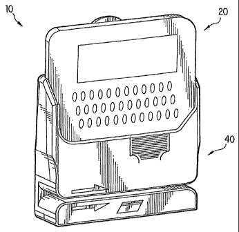
A caddy receivably retains a two-way messaging pager (20). The caddy has a
connector (65) for power and data transfer between the pager (20) and caddy.
The caddy is equipped with a magnetic strip card reader (40). This enables
remote transactions using a magnetic strip card such as a credit card or debit
card. The caddy has serial bus ports (58) for attaching the caddy to
peripheral
devices such as printers and taxi fare meters.


French Abstract

Cette invention concerne un boîtier pouvant recevoir un radiomessageur (20) à transmission bilatérale. Ce boîtier comporte un connecteur (65) permettant le transfert d'énergie et de données entre le radiomessageur (20) et le boîtier. Ce boîtier est pourvu d'un lecteur (40) de carte à bande magnétique. Ce dispositif permet d'effectuer des transactions à distance à l'aide d'une carte à bande magnétique telle qu'une carte de crédit ou de débit. Le boîtier comporte des ports de bus série (58) servant à relier le boîtier à des dispositifs périphériques tels que des imprimantes et des compteurs de taxi.

Claims

Note: Claims are shown in the official language in which they were submitted.


6
WHAT IS Claimed:

1. A pager caddy, comprising:
a housing, said housing having a cradle to
receivably retain a pager,
a magnetic strip reader, located in the housing,
and
a connector for engaging the pager to supply power
from the pager to said magnetic strip reader.

2. The pager caddy of claim 1, further comprising
serial bus ports for connecting said caddy to peripheral devices.
3. The pager caddy of claim 1, further comprising a
slot for receiving a card having a magnetic strip.

4. The pager caddy of claim 3, wherein said slot is in
a front face of said housing.

5. A pager caddy, comprising:
a housing receivably retaining a pager,
a magnetic strip reader, located in the housing,
a first connector for supplying power and data
transfer, and
a second connector for connecting the magnetic
strip reader to the pager, the second connector attached to the
first connector by a first cable.

6. The pager of claim 5, further comprising a serial
bus port in said housing, said serial bus port connected to the
first connector by a second cable.

Description

Note: Descriptions are shown in the official language in which they were submitted.


CA 02447316 2006-08-03

) 021093=160 PCT/US02/15131
CREDIT CARD AND BAR CODE READER MODULE
SACKGROUND OF THE INVENTION

Wireless communication allows people to create many
tasks without having to be near a computer or other device which
cannot be easily transported. The ability to send computer
generated voice messages, text messages, telefax messages, and
other information through a wireless device greatly enhances the
flexibility a person has in keeping in communication. The prior
art does not disclose a device that can be connected with an
existing pager to enable the reading of a card having a magnetic
strip.


CA 02447316 2003-11-17
WO 02/093460 PCT/US02/15131
2
SUtM4ARY OF THE INVENTION

A caddy receivably retains a two-way messaging pager.
The caddy has a connector for power and data transfer between the
pager and caddy. The caddy is equipped with a magnetic strip
card reader. This enables remote transactions using a magnetic
strip card such as a credit card or debit card. The caddy has
serial bus ports for attaching the caddy to peripheral devices
such as printers and taxi fare meters.


CA 02447316 2003-11-17
WO 02/093460 PCT/US02/15131
3

BRIEF DESCRIPTION OF THE DRAWINGS

FIGURE 1 is a front perspective view of the combined
pager and magnetic card reader;

FIGURE 2 is a rear perspective view of the combined
pager.and magnetic card reader;

FIGURE 3 is a front view of the combined pager and
magnetic card reader;

FIGURE'4 is a side view of the combined pager and
magnetic card reader;

FIGURE 5 is a top view of the combined pager and
,magnetic card reader;

FIGURE 6 is an exploded view of the combined pager and
magnetic card reader;

FIGURE 7 is a front view of the pager combined with an
optical code reader; and

FIGURE 8 is a bottom view of the caddy for the pager
having an optical code reader.


CA 02447316 2003-11-17
WO 02/093460 PCT/US02/15131
4
DETAILED DESCRIPTION OF THE INVENTION

The combined pager and magnetic card reader 10 is seen
in Figure 1. The device has a two way messenger pager 20
combined with a magnetic card reader 40 into one unit. The card
reader slot is in the front of the device and allows the user to
swipe the card either horizontally or vertically.
Turning now to Figure 2, the front view of the device
is seen. As is shown in the figure, the pager has a screen 24
for receiving and displaying messages and a keypad 22 for the
LO user to input commands and text. The front of the magnetic card
reader 40 has an upper portion 43 and a lower portion 44.
Between the two portions is the magnetic card slot 41. A card
having a magnetic strip is passed through the slot 41 in order
to be read. The front has a top edge 45 forming a cut-out
L5 portion for allowing continued access to the keyboard 22 when the
pager is connected to the magnetic card reader. A finger grip
portion 47 is formed in the front face for facilitating the
insertion and removal of the pager 20
Figure 3 is a rear perspective view of the device. The
20 back panel 55 supports a clip 57. The clip 57 can be of any
conventional design for attaching the device to a user's belt,
for instance. The side wall 52 of the magnetic card reader
connects the back wall 55 to the front wall upper portion 43. The
top edge 53 of the side wall 52 angles downwardly due to the
25 greater height of the rear wall 55 relative to the front wall 43.
Figure 4 is the side view of the combined pager and
magnetic card reader. The side wall 52 with the downwardly
angled top edge 53 is clearly seen, as is its position relative
to the pager 20. If desired, a serial port 58 is provided for
30 attaching printers, other computer hard drives, and the like.
Figure 5 shows the top view of the device. As can be
seen, when the two units of the pager 20 and magnetic card reader
40 are connected, they appear to be as one piece.
An exploded view of the device is shown in Figure 6.
35 Pager 20 is removably received within the card reading module 40.
The card reading slot 41 houses the magnetic strip reader 62.


CA 02447316 2003-11-17
WO 02/093460 PCT/US02/15131

The bottom front panel 44 extends below the card reading slot 41
and the upper front panel 43 extends above the card reading slot
41. The front panel 43 is formed as one piec'e with the side
panels 52. Rear panel 55 also has side panels formed as one
piece. When the front panel 43 and rear panel 55 are connected
to one another, the side panels complete channels for receiving
and retaining the pager 20. The pager 20 has a serial bus port
in its bottom surface. The serial bus port engages a connector
65 so that the magnetic strip reader 62 receives power from the
battery of the pager 20. The first connector 65 also provides
for data transfer between the pager 20 and the caddy. A second
connector 67 communicates between the magnetic strip reader and
first connector 65 via a cable(not shown). The magnetic card
reading module 40 can also have one or more serial bus port(s)
58 to connect the device to a peripheral device such as a
printer, bar code reader or personal computer. The serial bus
ports are connected to the first connector by a second cable 59.
There are many applications for the invention. It
allows for remote credit card transactions. One specific
application is the connection of the device to a taxi meter
through the serial bus port 58. The amount of the fare and
transaction approval can be communicated between the pager and
applicable financial institution.
. Figure 7 shows a similar device to that shown in
Figures 1-6 but having a caddy combinable to a pager having an
optical character reader (OCR) 75, commonly known as a bar code
reader, in the bottom of the caddy. The bar code reader 75 can
scan any bar code placed under the pager caddy when the bar code
reader is activated. The bar code reader would be connected to
the first connector 65 by a cable. Figure 8 shows the bottom of
the device with the bar code reader 75 clearly seen.
While the invention has been described with reference
to preferred embodiments, variations and modifications would be
apparent to one of ordinary skill in the art without departing
from the scope of the invention. Consequently, the appended
claims should not be limited to their literal terms, but should
be broadly construed in accordance with the scope of the
invention, as described above.

Representative Drawing
A single figure which represents the drawing illustrating the invention.
Administrative Status

For a clearer understanding of the status of the application/patent presented on this page, the site Disclaimer , as well as the definitions for Patent , Administrative Status , Maintenance Fee  and Payment History  should be consulted.

Administrative Status

Title Date
Forecasted Issue Date 2007-09-11
(86) PCT Filing Date 2002-05-17
(87) PCT Publication Date 2002-11-21
(85) National Entry 2003-11-17
Examination Requested 2003-11-17
(45) Issued 2007-09-11
Deemed Expired 2013-05-17

Abandonment History

There is no abandonment history.

Payment History

Fee Type Anniversary Year Due Date Amount Paid Paid Date
Request for Examination $200.00 2003-11-17
Registration of a document - section 124 $100.00 2003-11-17
Application Fee $150.00 2003-11-17
Maintenance Fee - Application - New Act 2 2004-05-17 $50.00 2004-04-08
Registration of a document - section 124 $100.00 2004-05-28
Maintenance Fee - Application - New Act 3 2005-05-17 $50.00 2005-02-17
Registration of a document - section 124 $100.00 2005-06-23
Maintenance Fee - Application - New Act 4 2006-05-17 $50.00 2006-02-07
Maintenance Fee - Application - New Act 5 2007-05-17 $100.00 2007-03-29
Final Fee $150.00 2007-06-29
Maintenance Fee - Patent - New Act 6 2008-05-19 $100.00 2008-04-03
Maintenance Fee - Patent - New Act 7 2009-05-18 $100.00 2009-04-21
Maintenance Fee - Patent - New Act 8 2010-05-17 $100.00 2010-04-21
Maintenance Fee - Patent - New Act 9 2011-05-17 $100.00 2011-05-17
Owners on Record

Note: Records showing the ownership history in alphabetical order.

Current Owners on Record
SABELLA, PAUL
CHARGE ANYWHERE LLC
Past Owners on Record
COMSTAR ACQUISITION, LLC
COMSTAR INTERACTIVE CORP.
Past Owners that do not appear in the "Owners on Record" listing will appear in other documentation within the application.
Documents

To view selected files, please enter reCAPTCHA code :


To view images, click a link in the Document Description column. To download the documents, select one or more checkboxes in the first column and then click the "Download Selected in PDF format (Zip Archive)" or the "Download Selected as Single PDF" button.

List of published and non-published patent-specific documents on the CPD .

If you have any difficulty accessing content, you can call the Client Service Centre at 1-866-997-1936 or send them an e-mail at CIPO Client Service Centre.


Document
Description 
Date
(yyyy-mm-dd) 
Number of pages   Size of Image (KB) 
Representative Drawing 2007-08-16 1 18
Cover Page 2007-08-16 1 46
Abstract 2003-11-17 1 12
Claims 2003-11-17 1 30
Drawings 2003-11-17 7 140
Description 2003-11-17 5 171
Representative Drawing 2003-11-17 1 25
Cover Page 2004-01-26 1 47
Description 2006-08-03 5 170
Claims 2006-08-03 1 28
Drawings 2006-08-03 7 144
Abstract 2007-02-14 1 12
Fees 2008-04-03 1 52
PCT 2003-11-17 2 116
Assignment 2003-11-17 6 169
Fees 2004-04-08 1 35
Assignment 2004-05-28 3 161
Correspondence 2004-07-06 1 14
Assignment 2004-08-30 1 34
Fees 2005-02-17 1 35
Assignment 2005-06-23 3 137
Prosecution-Amendment 2006-02-06 2 43
Fees 2006-02-07 1 36
Prosecution-Amendment 2006-08-03 5 125
Assignment 2006-08-04 1 41
Correspondence 2006-09-21 1 23
Fees 2007-03-29 1 55
Correspondence 2007-06-29 3 62
Fees 2009-04-21 1 50
Fees 2010-04-21 1 58
Fees 2011-05-17 1 44