Note: Descriptions are shown in the official language in which they were submitted.
CA 02447684 2003-11-14
WO 03/011767 PCT/US02/12924
IMPROVED KITCHEN GREASE REMOVAL SYSTEM
BACKGROUND OF THE INVENTION
The present invention relates to improvements in solids handling fox effluent
streams containing solids. The typical effluent stream for which the present
invention is
suitable is the discharge from a kitchen, particularly a restaurant kitchen.
Grease traps
and oil/grease separators for removal of the oil/grease components from such
effluents
are known. For example, the Lowe Engineering Company of Lincoln Park, N.J.
makes
products of this type, as shown in U.S. Pat. Nos. 4,051,024; 4,268,369 and
5,030,357. In
addition, Thermaco, Inc. of Asheboro, North Carolina, manufactures and sells
oil/grease
removal apparatus under the trademark BIG DIPPER. Exemplary of the patents
owned
by Thermaco are U.S. Pat. No. 4,235,726 to Shimko, U.S. Pat. No. 5,133,881 to
Miller et
al., and U.S. Patent No. 5,360,555 to Batten. The disclosures of these three
patents are
hereby incorporated by reference. The oil/grease separation devices marketed
by
I 5 Thermaco use various methods for the separation and removal of oil and
grease from
kitchen effluents, including the gravitational separation techniques and oil-
skimming
methods shown in the above patents.
Typically, oil/grease separators have infeed units including a straining
basket into
which the solids are directed and trapped to remove them from the flow so they
do not
interfere with the oil/grease removal process or with subsequent reprocessing
of the
removed oil/grease. It is up to a restaurant employee to periodically open the
unit and
remove the strainer basket and dump its contents. These strainers are
objectionable to
handle because the solids may have strong odors arid liquids may drip out of
the basket.
Since this is an unpleasant chore, sometimes it's not done. If the strainer
basket fills and
CA 02447684 2003-11-14
WO 03/011767 PCT/US02/12924
-18/6
is not emptied, the grease/oil separator unit may fail and cause the
associated plumbing
systems to backup.
Clearline Systems, Inc. of Asheboro, N.C. has.addressed these problems with
strainer baskets as shown in U.S. Patent No. 5,360,555 to the present
applicant by
providing a grinder/pump to periodically extract accumulated solids from an
oil/grease
separator device. The disclosure of this patent is hereby incorporated by
reference.
While this grinder/pump has proved effective to periodically remove separated
and
accumulated solids without the problems associated with strainer baskets, such
grinder/pumps have some limitations. Grinder/pumps require electric power and
periodic maintenance or replacement, and their moving parts may become jammed
by
certain kitchen solids such as bones, silverware, or rubber gloves. If
undetected, lodged
solids can cause grinder/pump motors to overheat and become damaged. A safety
hazard
exists when persons insert their hands into the inlets of such grinder/pumps
to remove .
lodged solids without taking proper safety precautions. Such grinder/pumps
often must
be removed and disassembled for servicing, typically by a manufacturer's
technician,
hired plumber or electrician.
Accordingly, there is a need in the art for an improvement in devices of this
nature to eliminate the problems caused by the presence of strainer baskets
and the
limitations of grinder/pumps or other similar mechanical pumps.
Eductors (also known as-"injectors", "jet pumps", or "ejectors") are known and
operate by taking advantage of the so-called "venturi effect" wherein
introduction of a
pressurized motive fluid into a cavity creates a suction in the cavity. This
suction in turn
draws another fluid or a mixture of another fluid and suspended solids into
and through
the cavity together with the motive fluid. Eductors are relatively simple and
inexpensive
compared to mechanical pumps. Eductors have no moving parts to wear or become
CA 02447684 2003-11-14
WO 03/011767 PCT/US02/12924
-17/6
damaged from use, and are therefore extremely durable in operation. In
addition,
eductors can be easily sized to suit a wide range of pumping demands.
Such eductors have been applied to address a number of needs. For example,
U.S. Patent No. 5,951,878 to Astrom discloses the use of eductors to clean
filtrate from a
disk filter apparatus. Similarly, U.S. Patent No. 6,083,384 to Al-AIi
discloses the use of
eductors to retrieve spilled oil. However, eductors have not been used
heretofore to
address the need for an improved method for removing solids from an oil/grease
separation device.
SUMMARY ~F THE INVENTION
The present invention fulfills this need in the art by providing an oil/grease
separation apparatus including an eductor system for extraction of accumulated
solids.
In a typical installation, the oil/grease separator includes a chamber having
an inlet
section for receiving a liquid flow containing water, oil/grease and gross
solids, a
downstream section for separating the oil or grease from the effluent, and an
outlet
section for discharge of the residual water through an outlet. The inlet
section is
provided with a water jet eductor having an extraction port in the lower
portion of the
inlet section. Gross solids entering the chamber settle in the inlet section
where they are
periodically removed by actuating the water jet eductor. The water jet eductor
is
actuated by opening a water supply valve to provide a flow of pressurized
water to the
eductor through a water supply line. The suction created by the water jet
eductor extracts
the accumulated solids from the inlet section through the extraction port.
Preferably, the inlet section has a bottom that slopes downwardly toward the
extraction port of the water jet eductor to direct accumulated solids toward
the extraction
port. The apparatus may also include a timer which automatically opens the
water
CA 02447684 2003-11-14
WO 03/011767 PCT/US02/12924
-16/6
supply valve to the eductor for a preset period at a preset time.
Alternatively, the water
supply valve may be opened by a weight-controlled switch in the inlet section
when a
preset weight of solids has been collected in the inlet section and closed
when the solids
have been depleted from the inlet section. The apparatus may also include a
grease trap
connected to receive the residual water exiting the chamber through the outlet
and piping
from the water jet eductor that bypasses the grease trap.
Preferably, the jet eductor includes an eductor pipe with a first end in
communication with the solids extraction port in a lower portion of the inlet
section. The
second end of the eductor pipe is connected to the outlet section of the
chamber. A jet
nozzle is provided in the inlet section of the oil/grease separation apparatus
and is
positioned to direct a j et of water into the first end of the eductor pipe in
the inlet section.
This jet of water creates a suction in the eductor pipe which causes a mixture
of water
and solids accumulated in the inlet section to be extracted from the inlet
section through
the eductor pipe.
Alternatively, the jet eductor may include an eductor housing in the inlet
section
of the chamber having a first opening forming a water injection port, a second
opening
forming a solids intake port, and a third opening in communication with the
solids
extraction port. A jet nozzle located inside the housing is connected to the
water
injection port to receive a supply of pressurized water through a supply line
and to direct
a jet of water through the discharge port. A discharge pipe connects the third
opening in
the eductor housing to the outlet section of the chamber. The jet of water
creates a
suction in the housing and discharge pipe, thereby causing the mixture of
water and
solids accumulated in the inlet section to be extracted from the inlet section
through the
discharge pipe. In a preferred arrangement, the eductor housing and discharge
pipe are
located internal to the chamber. Alternatively, the eductor housing and
discharge pipe
CA 02447684 2003-11-14
WO 03/011767 PCT/US02/12924
-15/6
may be external to the chamber. In this alternative installation, the solids
intake port in
the housing is connected to a penetration in an outer wall of the chamber in a
lower
portion of the inlet section.
In a typical installation, the oiI/grease separation apparatus includes a
chamber
for receiving a liquid flow containing water, oil/grease and gross solids.
The.chamber
has an inlet section, a downstream section and an outlet in an outlet section.
The inlet
section is separated from the downstream section by a weir which includes a
first wall
extending upwardly from the bottom of the chamber to a top above the outlet
and a
second wall extending downwardly from a height above the liquid level to a
submerged
level. The weir creates a higher static water level to be maintained in the
inlet section
than in the downstream section, and facilitates one-way passage of oil/grease
from the
inlet section to the downstream section. A water jet eductor is provided which
has an
extraction port in a lower portion of the inlet section for removal of
accumulated solids.
The inlet section includes an inlet port, a strainer separating the inlet port
and the top of
the first wall to inhibit the passage of solids to the downstream section, and
a bottom
which slopes downwardly toward the solids extraction port. An oil/grease
separator is
located in the downstream section for removing oillgrease from water held in
the
downstream section. Gross solids entering the chamber settle in the inlet
section for
periodic removal with some water by the water jet eductor. Oil/grease and
water
entering the chamber pass to the downstream section where the oil/grease is
removed
from the water, and the residual water exits the chamber through the outlet
section.
The invention also provides an oil/grease separation method that includes the
efficient removal of accumulated gross solids. The method includes introducing
a liquid
flow containing water, oil/grease and gross solids into a chamber having an
inlet section,
a downstream section and an outlet in an outlet section. The gross solids
entering the
CA 02447684 2003-11-14
WO 03/011767 PCT/US02/12924
-14/6
inlet section are permitted to settle in the inlet section where they are
periodically
removed with some water by actuating a water jet eductor. Oil/grease and water
are
permitted to pass from the inlet section to a downstream section where the
oil/grease is
removed from the water. Finally, the residual water is permitted to exit the
chamber
through the outlet.
Preferably, permitting oil/grease and water to pass from the inlet section to
the
downstream section includes passing the oil/grease and water over a weir that
maintains
a higher static water level in the inlet section than the downstream section.
The method
also preferably includes straining gross solids from the liquid flow by a
strainer in the
I O inlet section to prevent passage of solids to the downstream section.
Desirably, the
eductor is sized so that the periodic removal of solids creates a reverse flow
of water
through the strainer to backwash the strainer. 'The periodic removal of solids
may take
place for preset periods at a preset times. For example, this may take place
for thirty
seconds every thirty minutes. Alternatively, the periodic removal of solids
may take
place when a preset weight of solids has been collected in the inlet section
and end when
the solids have been depleted from the inlet section. In a typical
installation, the method
may include directing the residual water exiting the chamber through the
outlet section to
a grease trap and directing the solids and water removed from the inlet
section during the
periodic removal step to bypass the grease trap.
The invention may also include a focus plate to concentrate the oil/grease
atop
the water and a removal means to remove the concentrated oil/grease. The
focusing
plate may have a ridge aligned with a line between a receiving end and an exit
end of the
chamber.
CA 02447684 2003-11-14
WO 03/011767 PCT/US02/12924
-13/6
BRIEF DESCRIPTION OF THE DRAWINGS
The invention will be better understood from a reading of the detailed
description
of the preferred embodiments along with a review of the drawings in which:
FIG. 1 is side exterior view of a first embodiment of the invention;
FIG. 2 is a sectional view of the embodiment of FIG. l, taken along lines 2-2
and
looking in the direction of the arrows;
FIG. 3 is a sectional view of the embodiment of FIG. l, taken along lines 3-3
and
looking in the direction of the arrows;
FIG. 4 is a sectional view of the embodiment of FIG. 2, taken along lines 4-4
and
looking in the direction of the arrows;
FIG. 5 is a sectional view of the embodiment of FIG. 4, taken along lines 5-5
and
looking in the direction of the arrows;
FIG. 6 is a sectional view similar to the view of FIG. 5 showing an
alternative
piping arrangement;
FIG. 7 is a view similar to the view of FIG. 4 of a second embodiment of the
invention;
FIG. 8 is a sectional view of the embodiment of FIG. 7 taken along lines 8-8
and
looking in the direction of the arrows;
FIG. 9 is an enlarged detail view of the embodiment of FIG. 8;
FIG. 10 is a view similar to the view of FIG. 9 showing an alternative
arrangement for the eductor housing;
FIG. 11 is a side.view and partial section view of a third embodiment of the
invention having an eductor system external to the separator;
FIG. 12 is a plan view of the embodiment of FIG. 11;
FIG. 13 is an end view of the inlet and of the embodiment of Figures 11 and
12;
7
CA 02447684 2003-11-14
WO 03/011767 PCT/US02/12924
-12/6
FIG. 14 is a side sectional view of a fourth embodiment taken along line 14-14
in
FIG. 15;
FIG. 15 is a top view of the embodiment of FIG. 14 shown with the focusing
plate assembly removed;
FIG. 16 is a sectional view of the fourth embodiment taken along line 16-16 in
FIG. 15; and
FIG. 17 is a sectional view of the fourth embodiment taken along line 17-17 in
FIG. 15.
DETAILED DESCRIPTION OF THE PREFERRED EMBODIMENTS
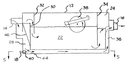
The present invention provides an oil/grease separator 10 including a water
jet
eductor for extraction and disposal of solids. As seen in Figures 1-S, a first
embodiment
includes a housing 12 having an inlet 14 and an outlet 16. As best seen in
FIG. 4, the
inlet 14, which can be connected to a discharge from a kitchen sink or the
like, deposits
kitchen effluent into an inlet chamber 28. The downstream edge of the inlet 28
is
defined by a weir 30 upstanding from the bottom portion of the housing 12. A
plate 32
extending down from the upper portion of the housing 12 cooperates with the
weir 30 to
provide a downwardly extending passage into a quiescent region 22. In the
quiescent
region 22, oil/grease and water reside for a long enough period of time so
that the
. ' oil/grease floats to the top of the water. The downstream edge of the
quiescent region 22
is defined by a baffle 34 extending downwardly from the housing 12. Water
passes from
the quiescent region 22 to an outlet chamber 24 by passing under the lower
edge of the
baffle 34. The water is then discharged from the outlet chamber 24 through the
outlet
16.
s
CA 02447684 2003-11-14
WO 03/011767 PCT/US02/12924
-11/6
The floating oil/grease can be removed in conventional fashion using any
desired
oil/grease separator such as those shown in the above-mentioned patents. For
example,
an oil-grease skimming device 38 may be provided to collect the floating
oil/grease from
the surface of the water. Alternatively, oil/grease removal methods or
apparatus as
disclosed in co-pending U.S. patent application 09/439,900 filed November 12,
1999, or
U.S. patent application 09/439,542 filed on November 12, 1999, the entire
disclosures of
which are hereby incorporated by reference, may be used.
As can be best seen in FIG. 4, the inlet chamber 28 is provided with a
downwardly extending strainer screen 46 attached to the housing 12 and the
weir 30.
Alternatively, a wedge-wire strainer basket may be used to prevent solids from
passing
out of the inlet chamber. As shown in FIG. 3, the inlet chamber 28 is provided
with a
sloping bottom 26. At the lower part of the sloping bottom is solids
extraction port 44 in
the weir 30. As best seen in FIG. 4, an eductor pipe 36 communicates with the
solids
extraction port 44 and extends to tie outlet 16. A water jet nozzle 40 in the
inlet
chamber 28 is positioned to direct a jet of water supplied through a water
supply line 18
into the solids extraction port 44. The supply of water to the nozzle 40 is
regulated by a
water supply valve 20 in the water supply line 18.
In operation, oil/grease and solids and water pass into the inlet chamber 28
from
the inlet 14. The oil/grease and water pass through the screen 46, over the
weir 30, and
into the quiescent region 22. However, solids are prevented from passing out
of the inlet
chamber 28 by the screen 46 and settle atop the sloping bottom 26 in the
region of the
solids extraction port 44. The accumulated solids are periodically removed
from the
inlet chamber by opening the water supply valve 18 to direct a jet of water
from the
nozzle 40 into the solids extraction port 44. The jet of water creates a
suction in the
eductor pipe 36 at the solids extraction port 44. The solids are thereby drawn
from the
CA 02447684 2003-11-14
WO 03/011767 PCT/US02/12924
-10/6
inlet chamber 28 into the eductor pipe 36 and pass through the eductor pipe 36
to the
outlet 16. The solids then pass together with the residual water exiting the
outlet 16 to a
grease trap. Alternatively, the solids may be directed to independent piping
152
connected to the eductor pipe 136 to bypass the grease trap, as shown in FIG.
6.
As discussed above, the water supply valve 20 is opened to supply water to the
nozzle 40 to activate the eductor system to periodically extract the
accumulated solids
from the oil/grease separator 10. In the embodiment shown in FIG. 5, a timer
52 is used
to open the water supply valve 20 at a preset time for a preset period of time
to discharge
whatever solids may be collected. In an alternate embodiment shown in FIG. 3,
a
weight-activated micro switch 42 at the bottom of the inlet chamber 28 is used
to sense a
threshold weight of solids and to open the supply valve 40 to activate the
eductor system.
Once the solids are substantially depleted from the inlet chamber, the micro
switch 42
closes the supply valve 20 to shut off the eductor system. In addition, other
control
mechanisms for the water supply valve may be substituted, as will be apparent
to those
skilled in the art. Also, the timer or switch can be used to start a pump or
other means
for inducing the liquid flow for the eductor.
A second embodiment of the invention is shown in Figures 7-9. In this
embodiment, an eductor housing 252 is provided at the bottom of the inlet
chamber 28
at the base of the sloping bottom 26. As best seen in the enlarged sectional
view of FIG.
9, the eductor housing 252 has a water injection port 256, a solids discharge
port 260,
and a solids intake port 258. As will be appreciated by those of ordinary
skill in the art,
the eductor housing 252 and its components may have a variety of
configurations other
than as depicted in the drawings. A water jet nozzle 240 is located inside the
eductor
housing 252 and is connected to a water supply line 218. The nozzle 240 is
positioned to
direct a jet of water through the discharge port 260. Alternatively, multiple
nozzles 240
to
CA 02447684 2003-11-14
WO 03/011767 PCT/US02/12924
-9/6
may be used in the eductor housing 252 (not shown). The solids discharge port
260 is
connected to a discharge pipe 236 which extends either to the outlet 16 of the
separator
or to independent piping for discharge of the solids. In operation, water is
supplied to
the nozzle 240 which directs a jet of water through the discharge port 260. A
suction is
5 created in the inside the eductor housing 252 which draws solids from the
inlet chamber
28 into the housing 252. The solids then pass with water out of the housing
252 through
the discharge port 260 and through the discharge pipe 236 for disposal.
As shown in FIG. 10, the eductor housing 352 may be external to the oil/grease
separator housing 12. The solids intake port 3 S 8 of the eductor housing 3 52
10 communicates with a solids outlet 350 in the housing 12 at the bottom of
the inlet
chamber 28. A water supply line 318 supplies water to a water jet nozzle 340
inside the
eductor housing 352. A solids discharge pipe 336 connects the solids discharge
port 360
in the housing 354 either to the separator outlet 16 or to independent piping.
In
operation, a jet of water from the nozzle 340 creates a suction in the eductor
housing
352. This suction causes the solids in the inlet chamber 28 to be extracted
from the
housing 12 through the solids outlet 350 and the discharge pipe 336.
A third embodiment is shown in Figures 11-13, wherein a solids extraction
chamber 470 extends from one side of the housing 12. A solids extraction
chamber 470
communicates with the inlet section 428 through a window 472. An eductor
nozzle 474
has one end connected to an opening in the top of the solids extraction
chamber 470 and
a second end connected to the outlet 416 by a discharge pipe 436. As best seen
in the
partial section of Figure 1 l, a small-diameter tube 476 extends through a
wall of the
eductor nozzle 474 to direct a jet of water into the discharge pipe 436. When
a water
supply valve 420 is opened, a jet of water is injected into the discharge pipe
436, thereby
causing solids with water to be drawn from the inlet section 428 into the
solids extraction
11
CA 02447684 2003-11-14
WO 03/011767 PCT/US02/12924
-8/6
chamber 470 through the nozzle 474 and to the outlet 416 through the discharge
pipe
436. Alternatively, the solids can be directed to alternate piping for
disposal.
A fourth embodiment is shown in Figures 14-17. A housing 512 has an inlet 514
and an outlet 516. Influent passes through the inlet 514 and into an inlet
chamber 528.
Heavy solids in the influent settle downwardly in the inlet chamber 528. A
grille 545
prevents large solids such as flatware or bones from passing to a lower
portion of the
inlet chamber 528. Smaller heavy solids pass through the grille 545, and are
directed to
a solids collection zone 527 by a sloping bottom 526. As best seen in Figures
15 and 17,
water, oil/grease, and fine floating solids pass from the inlet chamber 528 to
a quiescent
region 522 through slots 546 and 547. A baffle 548 may be provided in the
inlet
chamber 528 to prevent the momentum of incoming effluent from causing undue
water
passage through slots 547.
As best seen in Figures 14 and 15, an eductor tube 536 extends from the solids
collection zone 527 to an outlet 536. A water injection tube 576 extends into
the eductor
tube 536 as shown in Figure 15. As water is injected from tube 576 into the
eductor tube
536, accumulated solids are extracted from the collection zone 527 and
transferred out
through the eductor tube 536 to an outlet 537 for disposal.
As seen best in Figures 14 and 16, a focusing plate assembly 590 is provided
in
an upper portion of the housing S I2. Such focusing plates are disclosed in co-
pending
U.S. patent application 09/439,900 which was incorporated by reference above.
As seen
best in Figure 16, the bottom surface of the plate 590 causes oil/grease
floating near the
top of the quiescent region 522 to concentrate along a central region of the
housing. The
focusing plate 590 of this embodiment has a peak or ridge 591 that extends
along the
inlet-outlet axis of the apparatus. This is a presently preferred design to
enable
manufacturing flexibility. Larger or smaller size units can be made by making
the
12
CA 02447684 2003-11-14
WO 03/011767 PCT/US02/12924
-7/6
focusing plate longer or shorter without changing the shape of the plate. An
oil/grease
extraction tube 538 extends upward in the quiescent region to a height just
below the
static water level in the peak or ridge 591 of the focusing plate 590.
Floating oil/grease
is extracted through the tube 538 by activating'a fluid motivated pump 580,
which causes
the oil/grease to pass into the tube 538 and out through an exit port 595.
Fluid motivated
pumps are disclosed in co-pending U.S. patent application 09/567,778, filed
May 9,
2000, which is hereby incorporated by reference.
As will be appreciated, other eductor designs other than as specifically
depicted
and described may be substituted.
As will be apparent to those of ordinary skill in the art, the invention can
be
adapted to various types of oil/grease separators having solids accumulation
capability
and is not limited to the specific embodiments discussed above. Those of
ordinary skill in
the art will also appreciate that the invention could be carried out in other
various forms,
all of which are deemed to be within the scope of the appended claims.
13