Note: Descriptions are shown in the official language in which they were submitted.
CA 02448041 2003-11-07
RAILING SYSTEM
FIELD OF THE INVENTION
The present invention ,pertains to the field of railings, in particular to
railings of the type
having upper and lower members with a plurality of elements extending
therebetween.
BACKGROUND
Component railing systems, typically made of aluminium, have become
increasingly popular
because of their pleasing appearance, relatively low cost and general ease of
assembly and
installation.
Aluminium railings have many advantages over more traditional railing systems
of steel,
wrought iron or wood and, consequently, are widely used in many buildings for
balconies,
elevated decks and the like. They are light in weight, relatively inexpensive
and can be
painted to match any colour scheme. Furthermore, they have a virtually
unlimited life span.
Many such railing systems incorporate a plurality of spaced-apart pickets
extending between
top and bottom members. The top and bottom members may have channels for
receiving the
tops and bottoms of the pickets.
United States Patent No. 5,200,240 discloses an aluminium railing assembly,
which includes
a railing member comprising a hollow extrusion having a picket-receiving
channel along the
bottom thereof. The channel has an open bottom. The sides of the member have
bottom
edges, which extend downwardly at least as far as the bottom of the channel.
The railing
assembly includes the top railing member, a bottom railing member below the
top railing
member, a plurality of spaced-apart support posts extending between the
members and a
plurality of pickets between the posts. The support posts have flat tops which
are received
against the bottom of the top railing member and are connected thereto.
CA 02448041 2003-11-07
A railing system which incorporates continuous spacers is disclose in United
States Patent
No. 5,649,688. The railing system includes a top member having a downwardly
opening first
channel with a bottom and a bottom member having an upwardly opening second
channel
with a top. There is a plurality of spaced-apart vertical pickets, each picket
having a top end
in the first channel and a bottom end in the bottom channel, wherein there are
spacers
adjacent the top and bottom members. Each spacer is an elongated, continuous
member with
a plurality of spaced-apart openings and has a connector engaging ane of the
top and bottom
members. The pickets extend through the openings in the spacers pressing
against resilient
members which are provided along each of the channels. During assembly the
resilient
members are first fitted within i:he channels and the spacer members are then
secured to the
top and bottom members. The pickets can then be inserted through the openings
in the
elongated members and the elongated members are subsequently brought towards
each other
and secured in place with the pickets compressing the resilient members.
In addition, an aluminium railing system which incorporates pickets or glass
plates as the
vertical barriers is fabricated by Regal Aluminium Products. This system
comprises an upper
and lower member with spaced pickets connected therebetween. The separation
between the
adjacent pickets is covered by aluminium spacers, which clip onto both the
upper and lower
members, thereby attempting to disguise this separation.
However, some prior art aluminium railing systems have offered disadvantages
which have
limited their market. For example, some systems do not provide a clean,
pleasing appearance
from all angles, for example from below as they are seen by reclining sun
bathers. In
addition, the prior art railing systems may accidentally be dismantled due to
the form of
interconnection of several components. Therefore there is a need for an
improved railing
system.
This background information is provided for the purpose of making known
information
believed by the applicant to be of possible relevance to the present
invention. No admission
is necessarily intended, nor should be construed, that any of l;he preceding
information
constitutes prior art against the present invention.
2
CA 02448041 2003-11-07
SUMMARY OF THE INVENTION
An object of the present invention is to provide a railing system. In
accordance with an
aspect of the present invention, there is provided a railing system
comprising: a top member
having a downwardly opening first channel having a bottom, a length and an
interior, said top
member having a first interconnection mechanism associated with the bottom of
the first
channel, said first interconnection mechanism provided in the interior of the
first channel and
along the length of the first channel; a bottom member having an upwardly
opening second
channel having a top, a length and an interior, said bottom member having a
second
interconnection mechanism associated with the top of the second channel, said
second
interconnection mechanism provided in the interior of the second channel and
along the
length of the second channel; a plurality of spaced apart vertical members
having a top end in
the first channel and a bottom e:nd in the second channel; a plurality of top
member spacers
having opposite edges, said top member spacers having a third interconnection
mechanism
associated with each edge thereof, the third interconnection mechanism capable
of mating
with the first interconnection mechanism, said top member spacers enclosing an
opening in
the first channel located between the spaced apart vertical members; and a
plurality of bottom
member spacers having opposite edges, said bottom member spacers having a
fourth
interconnection mechanism associated with each edge thereof, the fourth
interconnection
mechanism capable of mating with the second interconnection mechanism, said
bottom
member spacers enclosing an opening in the second channel located between the
spaced apart
vertical members.
BRIEF DESCRIPTION OF THE FIGURES
Figure 1 illustrates a perspective view of the railing system in an erected
form according to
one embodiment of the present invention.
Figure 2A is a cross section of the top elongated member according to one
embodiment of the
present invention.
CA 02448041 2003-11-07
Figure 2B is a cross section of the top elongated member as shown in Figure
2A, wherein a
top spacer has been installed.
Figure 3A is a cross section of the bottom elongated member according to one
embodiment
of the present invention.
Figure 3B is a cross section of the bottom elongated member as shown in Figure
3A, wherein
a bottom spacer has been installed.
Figure 4 is a cross section of a top or bottom spacer according to one
embodiment of the
presentinvention.
Figure 5 is a perspective view of securing mounts and the top and bottom
elongated members
according to one embodiment of the present invention.
Figure 6 is a perspective view of securing mounts and the top and bottom
elongated members
according to another embodiment of the present invention.
Figure 7A is a cross section of a device according to one embodiment, that can
be inserted
into the downwardly and upwardly opening channels in order to retain a sheet
material in a
desired location.
Figure 7B is a cross section of a device according to one embodiment, which is
inserted into
the downwardly opening channels in order to retain a sheet material in a
desired location.
DETAILED DESCRIPTION OF THE IfNVENTION
The present invention provides a railing system that is modular and can be
interconnected in
an easy manner. The railing system comprises a top elongated member having a
downwardly
opening channel and a bottom elongated member having an upwardly opening
channel. A
number of spaced apart vertical members span the distance between the top and
bottom
members, wherein one end of a vertical member is inserted into the channel in
the top
4
CA 02448041 2003-11-07
member and the opposite end is inserted into the channel provided in the
bottom member.
The orientation and position of the top and bottom members is provided by the
interconnection of these elongated members to supports, or posts. Due to the
spaced apart
relation of the vertical members positioned in the channels, portions of the
top and bottom
channels are exposed. These exposed portions between the vertical members are
enclosed by
top and bottom spacers, which interconnect with the top and bottom members,
respectively.
A particular spacer is secured in a location within the cross section of the
top member or the
bottom member by one or more interconnection mechanisms. The interconnection
mechanisms associated with the edges of the spacers, mate with interconnection
mechanisms
provided along the length of the top and bottom members that are located on
the interior of a
channel at the open face thereof.
By providing interconnection mechanisms within the interior of a channel, the
spacers may
be more effectively secured to the top and bottom members thereby potentially
limiting their
accidental removal. In addition this method of interconnection within the
cross section of a
top or bottom member may enhance the structural integrity of the top and
bottom members as
well as possibly improve the aesthetics thereof.
With reference to Figure l, the railing system 10 according to one embodiment
ofthe present
invention is illustrated. The railing system comprises a top elongated member
20, a bottom
elongated member 30 and a plurality of vertical members 40. The top elongated
member 20
and the bottom elongated member 30 are secured in a desired location by
fastening these
members to a support 50, wherein the support can be a post, pole, wall or any
other support
which can provide the desired restraint as would be known to a worker skilled
in the art.
Optionally, the railing system comprises one or more intermediate supports 60
which may
reduce the potential bending of the bottom elongated member 30.
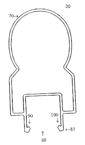
Top Elongated Member
In one embodiment of the present invention and with reference to Figure 2, the
top elongated
member 20 has an upper portion 70 which forms the top of the railing system
and therefore
may typically come into contact with a users hands, for example. The upper
portion 70 is
" a ~ .* Yw.: . a .. ,~.~~ _ . -~~~. .,~<...~ ~_."~ ;1,. ._u . . . .. .~ ~.
~,~,... ~, m....~. .. rt ~~....~~.~. _. ___._ .. _. _.... .,._
CA 02448041 2003-11-07
illustrated as a rounded surface at the top with vertical sides, however it
may equally well be
square, trapezoid, ellipse or any other shape desired as would be known to a
worker skilled in
the art. The top member additionally includes a downwardly opening channel 80
having a
bottom 85, which upon the fabrication of the top elongated member is
integrally connected to
the upper portion 70. This downwardly opening channel 80 receives one end of
the vertical
members (not shown) during the erection of the railing system.
Interconnection mechanisms 90 and 100 are associated with the interior of the
downwardly
opening channel and are located along the length of the channel and positioned
towards the
open face thereof, as illustrated. In this embodiment, the interconnection
mechanisms 90 and
100 are in the form of protrusions extending inwardly towards the centre of
the channel. This
form of interconnection mechanism may be termed a tongue of a tongue and
groove type
configuration as would be known to a worker skilled in the art. In an
alternate embodiment
the interconnection mechanism associated with the downwardly opening channel
may be a
single groove, double groove or any other type of interconnection mechanism as
would be
known to a worker skilled in the art. In addition the interconnection
mechanism associated
with one side of the downwardly opening channel may not b~e the same as that
associated
with the opposite side of this channel.
In one embodiment of the present invention, the inner sides of the downwardly
opening
channel are serrated thereby enabling the channel to grip the ends of the
vertical members
inserted therein. In an alternate embodiment a sleeve also having an open
side, may be
inserted into the downwardly opening channel, such that the openings are
oriented in the
same direction. For example the sleeve can be in a "U" shape which would be
compatible
with the downwardly opening channel as illustrated in Figure 2A. In this
embodiment, the
sleeve receives the ends of the vertical members and comprises serrated edges
along its
interior enabling the gripping of these vertical members. The sleeve can be
retained within
the channel by the interconnection mechanisms 90 and 100, for example, since
they protrude
towards the inside wall of the channel. Alternately, the sleeve may be
pressure fit into the
channel thereby securing it in the desired location. This sleeve may be
fabricated from any
type of material, for example a polymer, resin, plastic or any other material.
6
~_y....__.___ ____ _ _ ____.~_._....,~.,..:,~,;~....,<~. . . ~...._._._.___
___ ___.__ _____.___ __...~.._.~.,._.~,.~__~._~ _.__._ ._.~.._.. ..__.
CA 02448041 2003-11-07
In another embodiment of the present invention, the top elongated member may
only have a
downwardly opening channel without any interconnection mechanisms. A sleeve
may be
inserted into the downwardly opening channel wherein the sleeve has an
interconnection
mechanism as described and illustrated in Figure 2A. As such, the sleeve would
have an
interconnection mechanism may be termed a tongue of a tongue and grove type
configuration
as would be known by a worker skilled in the relevant art. The use of sleeve
with a
interconnection mechanism may reduce the manufacturing cost of the present
railing system.
With reference to Figure 2B, a top spacer 110 has been interconnected with the
top elongated
member thereby closing the downwardly opening channel 80. As illustrated the
top spacer is
installed within the cross section of the top elongated member thereby
potentially providing
improved structural integrity, improved resistance to removal and potentially
a mare
aesthetically pleasing shape.
Bottom Elongated Member
In one embodiment of the present invention, and with reference to Figure 3A,
the bottom
elongated member 30 comprises an upwardly opening channel 120 with a top 125.
This
upwardly opening channel 120 receives the end of the vertical members (not
shown) opposite
to that which was received by the top elongated member (not shown), during the
erection of
the railing system.
Interconnection mechanisms 130 and 140 are associated with the interior of the
upwardly
opening channel 120 and are located along the length of the channel and
positioned towards
the open face thereof, as illustrated. In this embodiment, the interconnection
mechanisms
130 and 140 are in the form of protrusions extending inwardly towards the
centre of the
channel. This form of interconnection mechanism may be termed a tongue of a
tongue and
groove type configuration as would be known to a worker skilled in the art. In
an alternate
embodiment the interconnection mechanism associated with the upwardly opening
channel
may be a single groove, double groove or any other type of interconnection
mechanism as
would be known to a worker skilled in the art. In addition the interconnection
mechanism
7
CA 02448041 2003-11-07
associated with one side of the downwardly opening channel may not be the same
as that
associated with the opposite side of this channel.
In one embodiment of the present invention, the inner sides of the upwardly
opening channel
are serrated thereby enabling the channel to grip the ends of the vertical
members inserted
therein. In an alternate embodiment a sleeve also having an open side, may be
inserted into
the upwardly opening channel, such that the openings are oriented in the same
direction. For
example the sleeve can be in a "U" shape which would be compatible with the
upwardly
opening channel as illustrated in Figure 3A. In this embodiment, the sleeve
receives the ends
of the vertical members and comprises serrated edges along its interior
enabling the gripping
of these vertical members. The sleeve can be retained within the channel by
the
interconnection mechanisms 130 and 140, for example, since they protrude
towards the
inside wall of this channel. Alternately, the sleeve may be pressure fit into
the channel
thereby securing it in the desired location. This sleeve may he fabricated
from any type of
material, for example a polymer, resin, plastic or any other material.
In another embodiment of the present invention, the bottom elongated member
may only
have a upwardly opening channel without any interconnection mechanisms. A
sleeve may be
inserted into the upwardly openang channel wherein the sleeve has an
interconnection
mechanism as described and illustrated in Figure 3A. As such, the sleeve would
have an
interconnection mechanism may be termed a tongue of a tongue and grove type
configuration
as would be known by a worker skilled in the relevant art. The use of sleeve
with a
interconnection mechanism may reduce the manufacturing cost of the present
railing system.
With reference to Figure 3B, a bottom spacer 150 has been interconnected with
the bottom
elongated member thereby closing the upwardly opening channel 120. As
illustrated the
bottom spacer is installed within. the cross section of the bottom elongated
member thereby
potentially providing improved structural integrity, improved. resistance to
removal and a
potentially more aesthetically pleasing shape.
CA 02448041 2003-11-07
Vertical Members
The vertical members of the present invention can take a plurality of forms.
The vertical
members may be solid or hollow members, however hollow members may be more
desirable
due to their lower weight compared to solid members. The cross sectional shape
of the
vertical members can be square:, rectangular, parallelogram, circular,
ellipsoid or any other
shape. These vertical members may be straight, curved or twisted, depending on
the desired
affect for the completed railing system. However, if the vertical members are
curved, they
should be curved in a plane perpendicular to the direction of the railing
system, for example
perpendicular to the longitudinal axis of the top and bottom elongated
members.
In one embodiment of the present invention the vertical members may be glass
panes, for
example tempered glass in order to reduce the possibility of breaking.
Alternately, the
vertical members may also be in the form of a sheet type material, for
example, fibreglass,
plastic or any other type of material. The thickness of this sheet type
material will be
dependent on the thickness of the upward and downward opening channels
associated with
the bottom and top elongated members, respectively.
Top ahd Bottom Spacers
The top and bottom spacers enable the enclosing of an exposed portion of the
downwardly
and upwardly opening channel, respectively, after the insertion of the
vertical members
therein. The top and bottom spacers have interconnection mechanisms associated
with two
opposite edges, wherein these interconnection mechanisms mate with the
interconnection
mechanisms associated with either the top elongated member or the bottom
elongated
member, as appropriate. Upon the installation of the spacers into their
desired location, they
are situated within the cross section of the appropriate elongated member as
illustrated in
Figures 2A and 3A. This design may improve the structural integrity of the top
and bottom
elongated members and may potentially increase their resistance to removal
whether
accidental or intentional.
34 In one embodiment of the present invention, the top and bottom spacers, 110
and 150,
respectively, are of the same design as illustrated in Figure 4. The spacers
include
9
. ,.,.. ..... ...n,~.. , s t... . ~wr ~<~uwa~,..s:~ae,~ :.~e uac~as~wwn .
~aw,~,r»m. wee ,.~..",r,~w.. n" .xn~w...,.," .. ...,..,".,~,R.:~;wwwe~.,..
.,.wra...<..,.xm::w.~arsa..,.-?c-~acr~-~e.~,~wux~rn~.,m~..v...,;.~,.p.,-
~:mn~xiw.,~.. ~.xvscw~a".~.,c..-n.
CA 02448041 2003-11-07
interconnection mechanisms which are fabricated into the opposite sides
thereof, wherein
these mechanisms mate with those in the top or bottom elongated members. In
this
embodiment, the interconnection mechanisms 160 and 170 are in the form of
protrusions
extending outwardly away from the centre of the spacer. This form of
interconnectian
mechanism may be termed a groove of a tongue and groove. type configuration as
would be
known to a worker skilled in the art. This groove within the spacers receives
the tongue
which is associated with the upwardly and downwardly opening channels of the
elongated
members as illustrated in Figures 2A and 3A. In an alternate embodiment, the
interconnection mechanism associated with the opposite edges of the spacers
may be a
tongue, double groove or any other type of interconnection mechanism as would
be known to
a worker skilled in the art. In addition, the interconnection mechanism
associated with one
edge of a spacer may not be the same as that associated with the opposite edge
of this spacer.
Furthermore, the top spacer may incorporate different interconnection
mechanisms to that of
the bottom spacer.
The bottom and top spacers can be manufactured having an end that is
compatible with the
shape of the vertical members. For example, the ends of the spacers can be
designed such
that, once installed, they abut the edge of the vertical member. Thus, if the
vertical member
has a convex curved side, the spacer which abuts this member will have a
compatible
concave curved end for suitable mating.
The components of the present invention can be fabricated from a number of
different
materials such that the selected material is appropriate for the desired
application of the
railing system. For example, a material can be selected based on its strength,
durability and
cost associated with manufacture. For example, the railing system can comprise
a plurality of
extruded aluminium members which may additionally be covered by a protective
finish or
colouring finish, as would be known to a worker skilled in the art. The
components could
optionally be fabricated from a polymer, plastic, fibreglass or metal.
In one embodiment of the present invention, securing mounts are provided in
order to
interconnect the top and bottom elongated members with a support for example,
a post, pole
..~. ~.r.
CA 02448041 2003-11-07
or a wall. The securing mounts can be configured such that their cross section
is identical to
that of either the top or bottom elongated member, except that it is slightly
larger thereby
enabling the appropriate member to slide therein. This secm°ing mount
can be connected to
the support prior to the insertion of the appropriate elongated member. A
worker skilled in
the art would understand how to design an appropriate securing mount such that
the desired
affect is realised. Figure 5 illustrates one example of this form of securing
mount. The
securing mount 170 is designed to mate and secure the top e:(ongated member 20
and the
securing mount 180 is designed to mate and secure the bottom elongated member
30. Both
securing mounts 170 and 180 are fixed to another structure through the use of
screws, for
example, positioned in the holes 190 of the securing mounts.
In an alternate embodiment, the securing mounts can additionally comprise a
hinging
mechanism such that an elongated member can be connected( to a support wherein
the
elongated member does not intersect with the support at a perpendicular angle.
Figure 6
illustrates one example of this form of securing mount. The securing mount 200
has a hinge
mechanism enabling some movement of the top elongated member 20 and the
securing
mount 210 also has a hinge mechanism enabling some movement of the bottom
elongated
member 30. Both securing mounts 200 and 210 are fixed to another structure
through the use
of screws, for example, positioned in the holes 220 of the securing mounts.
In one embodiment, the vertical members are sheets of material, for example a
pane of glass
or a polymer sheet. In order to secure this form of sheet material within the
railing system, a
securing system 230, as illustrated in Figure 7A can be used. This securing
system 230 is
placed within the channel in both the top and bottom elongated members. The
securing
system 230 comprises an open channel 240 having serrated edges 250 within the
interior
thereof for securing the sheet material. The securing system further comprises
interconnection mechanisms 270 and 280 that mate with the interconnection
mechanisms of
the top or bottom elongated members thereby retaining the securing system at
the desired
location. The interconnection mechanism of the securing system may be termed a
groove of
a tongue and groove type configuration as would be known b~y a worker skilled
in the
relevant art. The top portion 280 of the securing system 230 provides a
surface for the
11
CA 02448041 2003-11-07
abutment of the sheet material upon its installation. The securing system 230
can be formed
from a rigid material or a flexible material wherein a flexible material will
allow for the
potential of an improved interconnection with the sheet material and
additionally may allow
for the compression of the top portion 280 thereby enabling the formation of a
tight fit
between the top and bottom elongated members and the sheet material. With
reference to
Figure 7B, the securing system 230 is installed in the channel 80 of an
elongated top member
20.
The embodiments of the invention being thus described, it will be obvious that
the same may
be varied in many ways. Such variations are not to be regarded as a departure
from the spirit
and scope of the invention, and all such modifications as would be obvious to
one skilled in
the art are intended to be included within the scope of the following claims.
12