Language selection

Search

Patent 2448249 Summary

Third-party information liability

Some of the information on this Web page has been provided by external sources. The Government of Canada is not responsible for the accuracy, reliability or currency of the information supplied by external sources. Users wishing to rely upon this information should consult directly with the source of the information. Content provided by external sources is not subject to official languages, privacy and accessibility requirements.

Claims and Abstract availability

Any discrepancies in the text and image of the Claims and Abstract are due to differing posting times. Text of the Claims and Abstract are posted:

  • At the time the application is open to public inspection;
  • At the time of issue of the patent (grant).
(12) Patent Application: (11) CA 2448249
(54) English Title: A PIPE FITTING COMPRISING A BODY AND A NUT
(54) French Title: RACCORD COMPRENANT UN CORPS ET UN ECROU
Status: Deemed Abandoned and Beyond the Period of Reinstatement - Pending Response to Notice of Disregarded Communication
Bibliographic Data
(51) International Patent Classification (IPC):
  • F16L 19/06 (2006.01)
  • F16L 19/065 (2006.01)
(72) Inventors :
  • VAN WYK, HENDRIK (South Africa)
(73) Owners :
  • HENDRIK VAN WYK
(71) Applicants :
  • HENDRIK VAN WYK (South Africa)
(74) Agent: MARKS & CLERK
(74) Associate agent:
(45) Issued:
(86) PCT Filing Date: 2002-03-26
(87) Open to Public Inspection: 2002-10-10
Availability of licence: N/A
Dedicated to the Public: N/A
(25) Language of filing: English

Patent Cooperation Treaty (PCT): Yes
(86) PCT Filing Number: PCT/ZA2002/000049
(87) International Publication Number: WO 2002079683
(85) National Entry: 2003-11-20

(30) Application Priority Data:
Application No. Country/Territory Date
2001/2615 (South Africa) 2001-03-30

Abstracts

English Abstract


A pipe fitting according to the invention comprises a body (1.1) and a nut(2),
the body (1.1)having at least one sleeve adapted to snugly receive a pipe end
(7) and provided with external threading(14) and a spigot(11), the spigot(11)
having at its leading end an external partly tapered forward section(12), and
the nut(2) having internal threading which matches the external threading(14)
on the sleeve and an internal taper(10) at the far end of the threading, the
arrangement of the forward section, tapers and threading being such that when
the sleeve and the nut are screwed together the forward section of the
spigot(11) comes into contact with the internal taper(10) of the nut and is
deflected inwardly to grip a pipe end (7) which is in the sleeve.


French Abstract

L'invention concerne un raccord comprenant un corps (1, 1) et un écrou (2), le corps (1,1) ayant au moins un manchon destiné à recevoir par ajustement serré une extrémité de tuyau (7) et doté d'un filetage externe (14) et d'un bout mâle (11) ayant sur son extrémité avant une partie avant (12) externe et partiellement conique. L'écrou (2) présente un filetage interne qui épouse le filetage externe (14) pratiqué sur le manchon et un cône interne (10) au niveau de l'extrémité éloignée du filetage. La partie avant, les cônes et le filetage sont disposés de manière que, lorsque le manchon et l'écrou sont vissés ensemble, la partie avant du bout mâle (11) entre en contact avec le cône interne (10) de l'écrou et soit déviée vers l'intérieur afin de saisir une extrémité (7) du tuyau qui se trouve dans le manchon.

Claims

Note: Claims are shown in the official language in which they were submitted.

CLAIMS
1. A pipe fitting comprising a body and a nut, the body having at least one
sleeve
adapted to snugly receive a pipe end and,provided with external threading and
a
spigot, the spigot having at its leading end a truncated nose section and an
external partly tapered forward section, the angle of the external taper on
the
forward section of the spigot being between 50° and 80°to a
transverse section
through the sleeve and the nut having internal threading which matches the
external threading on the sleeve and an internal taper at the far end of the
threading, the angle of the internal taper on the nut being at least
10° less than
that of the external taper and in the range of 50° to 30° to a
transverse section
through the nut, the arrangement of the forward section, tapers and threading
being such that when the sleeve and the nut are screwed together the forward
section of the spigot comes into contact with the internal taper of the nut
and is
deflected inwardly to grip and seal a pipe end which is in the sleeve.
2. A pipe fitting as claimed in claim 1 in which the angle of the external
taper on
the front section of the spigot is 70° leading to a nose section of
90° and the
internal taper on the nut is 45°.
3. A pipe fitting as claimed in any of the preceding claims in which the body
is a
coupling.
4. A pipe fitting as claimed in any of claims 1 to 3 in which the body is a
tee.
5. A pipe fitting as claimed in any of claims 1 to 3 in which the body is a
bend.
6. A pipe fitting as claimed in any of claims 1 to 3 in which the body is a
cross.
7. A method of joining pipes in which a pipe is inserted into a pipe fitting
as
claimed in any of the preceding claims, and the sleeve and nut are screwed
together.
6

Description

Note: Descriptions are shown in the official language in which they were submitted.


01-03-2003
CA 02448249 2003-11-20 ' ~A0200049
PIPE FITTINGS
FIELD OF INVENTION ~ .
:a
.j
This invention relates to pipe fittings used to connect pipes to one another
and to other
components of an installation.
BACKGROUND TO THE INVENTION
1o Conventional pipe fittings are used to connect pipes to one another and to
other
components of an installation. In its sirilplest form such a pipe'fitting
includes a body
with an externally threaded socket into which the pipe end is inserted until
it
encounters an end stop. Before inserting the pipe end into the socket, the
pipe end is
passed through an internally threaded nut and a ferrule. Because of its shape
a ferrule
t5 is often referred to in the plumbing trade as an "olive". The ferrule
encircles the pipe
and is against the end of the socket. When the nut is screwed onto the socket
and
,tightened, the olive is crushed against the pipe forming both a seal and a
means which
grips the pipe and prevents it being pulled out of the socket. The body can
have one,
two or three or more sockets depending on the intended use. Examples of bodies
are a
20 ~ tee, a bend, a coupling arid a cross.
Figure 1 of the drawings illustrates the way in which conventional pipe
fittings are
used to connect pipes to one another and to other components of an
installation.
Figure 1 illushates 3 possible ways in which water may flow should a leak
occur.
Arrow 4 shows that water may flow between the pipe and the olive. Arrow 5
shows
25 that water may flow between the body and the olive and then between the
olive and the
nut. Arrow 6 shows that water may flow between the nut and the body.
Referring to Figure 2 of the drawings, there is shov~:n a fitting according to
an earlier
invention by the present iinventox. . This is shown to illustrate that with
that invention
there are two possible routes in which water may flow. Usually no water
escapes but
30 it is possible that in a few instances leaks may occur. Tf there is a Leak,
water may
flow as shown by Arrow 9 between the body and the nut, or as shown by Arrow 8
between the pipe and the nut.
AMENDED SHEET

01;0-2003 .
~~ ~ CA 02448249 2003-11-20 ' ZA0200049
The earlier invention offers the following advantages inter alia over the
prior art:-
1. The number of possible escape routes for water is reduced from three to
two.
2. There is a considerable reduction in the amount of material needed to '
manufacture'equivalent fittings.
An object of the present invention is to make further improvements on both the
above
mentioned advantages.
SUMMARY OF INWENTION.
to A pipe fitting according to the invention comprises a body and a nut, the
body having
at least one sleeve adapted to snugly receive ~a. pipe end and provided
with'external'
threading and a spigot, the spigot having at its leading end a truncated nose
section and
an external partly tapered forward section, the angle of the external tapei on
the
forward section of the spigot being between 50° and 80° to a
transverse section through
~ the sleeve and the nut having internal threading which matches the external
threadirig
on the sleeve and an internal taper at the far end of the threading, the angle
of the
internal taper on the nut being at least 10° less than that of the
external taper and in the
range of 50° to 30° to a transverse section through the nut, the
arrangement of the
forward section, tapers, and threading being such that when the sleeve and the
nut are
20. screwed together the forward section of the spigot comes into contact with
the internal
taper of the nut and is deflected inwardly to grip and seal a pipe end which
is in the
sleeve.
Further in a pipe fitting according to the invention the angle of the external
taper on the
front. section of the spigot is 70° leading to a nose section of
90° and the internal taper
on the nut is 45°.
The body in a~pipe fitting according to the invention may be a coupling.
The body in a pipe fitting according to the invention may be a tee.
The body in a pipe fitting according to the invention may be a bend.
The body in a pipe fitting according to the invention may be a cross.
3o Further the invention includes a method of joining pipes in which a pipe is
inserted into
a pipe fitting according to the invention, and the sleeve and nut are screwed
together.
2
AMENDED SHEE T

01-03-2003 ' ~" CA 02448249 2003-11-20 ' ZA0200049
BRIEF DESCRIPTION OF DRAWINGS
For a better understanding of the present invention, and to show how the same
inay be
carried into effect, reference will now be made by way of example to the ,
accompanying drawings in which :-
FIGURE 1 is a section through a conventional pipe fitting ~ w
FIGURE 2 is a section through a pipe fitting according to an earlier '
invention of the inventor.
FIGURE 3 is a section through a coupling body according to the present
to ' invention
FIGURE 4 is ~a section through~a nut ~tised iri-conjunctiori with'thewcoupling
shown in Figure 3 . .
. FIGURE 5 is a detail of the spigot end shown at 11 in Figure 3
' FIGURE 6 is a, section through a T - body according to the present ~ .
' ~ invention ' '
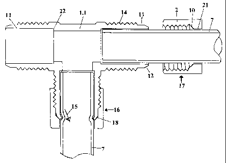
' ~ FIGURE 7 is a section through a T - body and nuts illustrating how a pipe
' ; ~ is fitted according to the present invention ~ . ~ ~ .
3
AMENDED SHEET

S
,. ,
01-03-2003 ~ ' ~ CA 02448249 2003-11-20 ' ZA0~00049-
BEST MODE OF CARRYING OUT TIE INVENTION . . '~
One form of the present invention is a pipe fitting comprising a coupling body
1 shown
in Figure 3 and nut 2 shown in Figure 4. The coupling body I is provided with
an
5~ external thread I4 and a spigot 11 at both ends. A detail of the spigot 11
is shown in
Figure 5. The spigot has a taper 12 having an angle of 70° and a
90° nose section 13.
An internal stop 22 is provided. The end of a pipe to be fitted wilt abut
against the
stop 22 (see Figure 7). .
The nut 2 has a sleeve 20 having axi internal thread 19 which matches the
external
0 0 thread 14 of the coupling body 1. The internal thread 19 commences at one
opening
of the nut ~2 and extends inwardly to a taper 10 near the far erid. 'From the
taper 10 to
the other open end there is a cylindrical section 2I . Instead of a coupling
body 1 a T-
body l .l shown in Figure 6 and having three openings; or even .a cross (not
illustrated)
having four openings maybe used. Each branch has an external thread 14 and
spigot
15 11 with taper 12 and flattened nose 13.
The manner in which the invention operates can be best seen in Figure 7.
A pipe 7 is fed through nut 2 and pushed up against stop 22. ' At 17 a nut is
shown
before it has been screwed onto the T-body 1:1. At 16 the nut is shown.in
compressed
condition i.e. after it has been screwed on and tightened. As the spigot 11
approaches
20 the far end of the nut 2 its taper 12 engages the taper 10 and it is
deflected inwards.
.~ The 90° nose section 13 "bites" into the pipe ? and grips it.
The tapered section 12 on ~fihe spigot 11 may be 70° while the taper 10
on the nut 2 may
be 45°. This an-angement greatly brings down the torque levels required
to tighten the
nut 2. ~ As the nut 2 is tightened the taper I2 deforms against the taper 10
of the nut and
25 ~ takes up a 45° angle against the taper of the nut. As this happens
the sealing effect
takes place and the pipe does not rotate as the nut 2 is being tightened. If
the pipe
needs to be rotated after this, it is necessary first to loosen the nut 2 and
to rotate the
' pipe by hand or with a suitable tool. Due to the 90° nose section the
square section
almost immediately bites into the pipe. ,This also prevents the pipe being
shaved oil
30 by the harder material.
Should a leak occur, there is only one possible direction for water to escape.
This is
along the pipe between the pipe and the. body past the depression I8 on the
pipe and
past the nut 2 as indicated by arrow 15.
4
AMENDED SHEET

..
0'!-'03-2003 '~ CA 02448249 2003-11-20 ~ . ~A0200049
It is also possible to vary the profile of the spigot l l without detracting
'from the .
., invention. For example instead of a taper 12 and a truncated section 13 the
profile may
be a curve (nof illustrated). v..
This feature is a considerable improvement over the earlier invention. A
further
advantage is that there is a considerable saving in material needed to make
pipe fittings
according to this invention when compared to conventional fittings and
fittings
according to the earlier invention.
Lt is to be understood that the nut and body together constitute a pipe
fitting.
1o . '
INDUSTRIAL APPLICATION ~ ~ ' '
' Pipe fittings according to the invention will have countless applications in
the
domestic, industrial, commercial and agricultural sectors.
. '
ao
30
5
AMl=NDl=D SNE~~

Representative Drawing
A single figure which represents the drawing illustrating the invention.
Administrative Status

2024-08-01:As part of the Next Generation Patents (NGP) transition, the Canadian Patents Database (CPD) now contains a more detailed Event History, which replicates the Event Log of our new back-office solution.

Please note that "Inactive:" events refers to events no longer in use in our new back-office solution.

For a clearer understanding of the status of the application/patent presented on this page, the site Disclaimer , as well as the definitions for Patent , Event History , Maintenance Fee  and Payment History  should be consulted.

Event History

Description Date
Inactive: Agents merged 2006-08-10
Application Not Reinstated by Deadline 2006-03-27
Time Limit for Reversal Expired 2006-03-27
Deemed Abandoned - Failure to Respond to Maintenance Fee Notice 2005-03-29
Inactive: Cover page published 2004-01-30
Inactive: Notice - National entry - No RFE 2004-01-27
Inactive: Inventor deleted 2004-01-27
Inactive: Agents merged 2004-01-06
Application Received - PCT 2003-12-11
National Entry Requirements Determined Compliant 2003-11-20
Application Published (Open to Public Inspection) 2002-10-10

Abandonment History

Abandonment Date Reason Reinstatement Date
2005-03-29

Maintenance Fee

The last payment was received on 2004-02-02

Note : If the full payment has not been received on or before the date indicated, a further fee may be required which may be one of the following

  • the reinstatement fee;
  • the late payment fee; or
  • additional fee to reverse deemed expiry.

Please refer to the CIPO Patent Fees web page to see all current fee amounts.

Fee History

Fee Type Anniversary Year Due Date Paid Date
Reinstatement (national entry) 2003-11-20
Basic national fee - standard 2003-11-20
MF (application, 2nd anniv.) - standard 02 2004-03-26 2004-02-02
Owners on Record

Note: Records showing the ownership history in alphabetical order.

Current Owners on Record
HENDRIK VAN WYK
Past Owners on Record
None
Past Owners that do not appear in the "Owners on Record" listing will appear in other documentation within the application.
Documents

To view selected files, please enter reCAPTCHA code :


To view images, click a link in the Document Description column. To download the documents, select one or more checkboxes in the first column and then click the "Download Selected in PDF format (Zip Archive)" or the "Download Selected as Single PDF" button.

List of published and non-published patent-specific documents on the CPD .

If you have any difficulty accessing content, you can call the Client Service Centre at 1-866-997-1936 or send them an e-mail at CIPO Client Service Centre.


Document
Description 
Date
(yyyy-mm-dd) 
Number of pages   Size of Image (KB) 
Description 2003-11-20 5 229
Abstract 2003-11-20 2 62
Claims 2003-11-20 1 47
Drawings 2003-11-20 4 44
Representative drawing 2004-01-30 1 8
Cover Page 2004-01-30 1 40
Reminder of maintenance fee due 2004-01-27 1 107
Notice of National Entry 2004-01-27 1 190
Courtesy - Abandonment Letter (Maintenance Fee) 2005-05-24 1 174
PCT 2003-11-20 14 518
Fees 2004-02-02 1 29