Sélection de la langue

Search

Sommaire du brevet 2448249 

Énoncé de désistement de responsabilité concernant l'information provenant de tiers

Une partie des informations de ce site Web a été fournie par des sources externes. Le gouvernement du Canada n'assume aucune responsabilité concernant la précision, l'actualité ou la fiabilité des informations fournies par les sources externes. Les utilisateurs qui désirent employer cette information devraient consulter directement la source des informations. Le contenu fourni par les sources externes n'est pas assujetti aux exigences sur les langues officielles, la protection des renseignements personnels et l'accessibilité.

Disponibilité de l'Abrégé et des Revendications

L'apparition de différences dans le texte et l'image des Revendications et de l'Abrégé dépend du moment auquel le document est publié. Les textes des Revendications et de l'Abrégé sont affichés :

  • lorsque la demande peut être examinée par le public;
  • lorsque le brevet est émis (délivrance).
(12) Demande de brevet: (11) CA 2448249
(54) Titre français: RACCORD COMPRENANT UN CORPS ET UN ECROU
(54) Titre anglais: A PIPE FITTING COMPRISING A BODY AND A NUT
Statut: Réputée abandonnée et au-delà du délai pour le rétablissement - en attente de la réponse à l’avis de communication rejetée
Données bibliographiques
(51) Classification internationale des brevets (CIB):
  • F16L 19/06 (2006.01)
  • F16L 19/065 (2006.01)
(72) Inventeurs :
  • VAN WYK, HENDRIK (Afrique du Sud)
(73) Titulaires :
  • HENDRIK VAN WYK
(71) Demandeurs :
  • HENDRIK VAN WYK (Afrique du Sud)
(74) Agent: MARKS & CLERK
(74) Co-agent:
(45) Délivré:
(86) Date de dépôt PCT: 2002-03-26
(87) Mise à la disponibilité du public: 2002-10-10
Licence disponible: S.O.
Cédé au domaine public: S.O.
(25) Langue des documents déposés: Anglais

Traité de coopération en matière de brevets (PCT): Oui
(86) Numéro de la demande PCT: PCT/ZA2002/000049
(87) Numéro de publication internationale PCT: WO 2002079683
(85) Entrée nationale: 2003-11-20

(30) Données de priorité de la demande:
Numéro de la demande Pays / territoire Date
2001/2615 (Afrique du Sud) 2001-03-30

Abrégés

Abrégé français

L'invention concerne un raccord comprenant un corps (1, 1) et un écrou (2), le corps (1,1) ayant au moins un manchon destiné à recevoir par ajustement serré une extrémité de tuyau (7) et doté d'un filetage externe (14) et d'un bout mâle (11) ayant sur son extrémité avant une partie avant (12) externe et partiellement conique. L'écrou (2) présente un filetage interne qui épouse le filetage externe (14) pratiqué sur le manchon et un cône interne (10) au niveau de l'extrémité éloignée du filetage. La partie avant, les cônes et le filetage sont disposés de manière que, lorsque le manchon et l'écrou sont vissés ensemble, la partie avant du bout mâle (11) entre en contact avec le cône interne (10) de l'écrou et soit déviée vers l'intérieur afin de saisir une extrémité (7) du tuyau qui se trouve dans le manchon.


Abrégé anglais


A pipe fitting according to the invention comprises a body (1.1) and a nut(2),
the body (1.1)having at least one sleeve adapted to snugly receive a pipe end
(7) and provided with external threading(14) and a spigot(11), the spigot(11)
having at its leading end an external partly tapered forward section(12), and
the nut(2) having internal threading which matches the external threading(14)
on the sleeve and an internal taper(10) at the far end of the threading, the
arrangement of the forward section, tapers and threading being such that when
the sleeve and the nut are screwed together the forward section of the
spigot(11) comes into contact with the internal taper(10) of the nut and is
deflected inwardly to grip a pipe end (7) which is in the sleeve.

Revendications

Note : Les revendications sont présentées dans la langue officielle dans laquelle elles ont été soumises.


CLAIMS
1. A pipe fitting comprising a body and a nut, the body having at least one
sleeve
adapted to snugly receive a pipe end and,provided with external threading and
a
spigot, the spigot having at its leading end a truncated nose section and an
external partly tapered forward section, the angle of the external taper on
the
forward section of the spigot being between 50° and 80°to a
transverse section
through the sleeve and the nut having internal threading which matches the
external threading on the sleeve and an internal taper at the far end of the
threading, the angle of the internal taper on the nut being at least
10° less than
that of the external taper and in the range of 50° to 30° to a
transverse section
through the nut, the arrangement of the forward section, tapers and threading
being such that when the sleeve and the nut are screwed together the forward
section of the spigot comes into contact with the internal taper of the nut
and is
deflected inwardly to grip and seal a pipe end which is in the sleeve.
2. A pipe fitting as claimed in claim 1 in which the angle of the external
taper on
the front section of the spigot is 70° leading to a nose section of
90° and the
internal taper on the nut is 45°.
3. A pipe fitting as claimed in any of the preceding claims in which the body
is a
coupling.
4. A pipe fitting as claimed in any of claims 1 to 3 in which the body is a
tee.
5. A pipe fitting as claimed in any of claims 1 to 3 in which the body is a
bend.
6. A pipe fitting as claimed in any of claims 1 to 3 in which the body is a
cross.
7. A method of joining pipes in which a pipe is inserted into a pipe fitting
as
claimed in any of the preceding claims, and the sleeve and nut are screwed
together.
6

Description

Note : Les descriptions sont présentées dans la langue officielle dans laquelle elles ont été soumises.

01-03-2003
CA 02448249 2003-11-20 ' ~A0200049
PIPE FITTINGS
FIELD OF INVENTION ~ .
:a
.j
This invention relates to pipe fittings used to connect pipes to one another
and to other
components of an installation.
BACKGROUND TO THE INVENTION
1o Conventional pipe fittings are used to connect pipes to one another and to
other
components of an installation. In its sirilplest form such a pipe'fitting
includes a body
with an externally threaded socket into which the pipe end is inserted until
it
encounters an end stop. Before inserting the pipe end into the socket, the
pipe end is
passed through an internally threaded nut and a ferrule. Because of its shape
a ferrule
t5 is often referred to in the plumbing trade as an "olive". The ferrule
encircles the pipe
and is against the end of the socket. When the nut is screwed onto the socket
and
,tightened, the olive is crushed against the pipe forming both a seal and a
means which
grips the pipe and prevents it being pulled out of the socket. The body can
have one,
two or three or more sockets depending on the intended use. Examples of bodies
are a
20 ~ tee, a bend, a coupling arid a cross.
Figure 1 of the drawings illustrates the way in which conventional pipe
fittings are
used to connect pipes to one another and to other components of an
installation.
Figure 1 illushates 3 possible ways in which water may flow should a leak
occur.
Arrow 4 shows that water may flow between the pipe and the olive. Arrow 5
shows
25 that water may flow between the body and the olive and then between the
olive and the
nut. Arrow 6 shows that water may flow between the nut and the body.
Referring to Figure 2 of the drawings, there is shov~:n a fitting according to
an earlier
invention by the present iinventox. . This is shown to illustrate that with
that invention
there are two possible routes in which water may flow. Usually no water
escapes but
30 it is possible that in a few instances leaks may occur. Tf there is a Leak,
water may
flow as shown by Arrow 9 between the body and the nut, or as shown by Arrow 8
between the pipe and the nut.
AMENDED SHEET

01;0-2003 .
~~ ~ CA 02448249 2003-11-20 ' ZA0200049
The earlier invention offers the following advantages inter alia over the
prior art:-
1. The number of possible escape routes for water is reduced from three to
two.
2. There is a considerable reduction in the amount of material needed to '
manufacture'equivalent fittings.
An object of the present invention is to make further improvements on both the
above
mentioned advantages.
SUMMARY OF INWENTION.
to A pipe fitting according to the invention comprises a body and a nut, the
body having
at least one sleeve adapted to snugly receive ~a. pipe end and provided
with'external'
threading and a spigot, the spigot having at its leading end a truncated nose
section and
an external partly tapered forward section, the angle of the external tapei on
the
forward section of the spigot being between 50° and 80° to a
transverse section through
~ the sleeve and the nut having internal threading which matches the external
threadirig
on the sleeve and an internal taper at the far end of the threading, the angle
of the
internal taper on the nut being at least 10° less than that of the
external taper and in the
range of 50° to 30° to a transverse section through the nut, the
arrangement of the
forward section, tapers, and threading being such that when the sleeve and the
nut are
20. screwed together the forward section of the spigot comes into contact with
the internal
taper of the nut and is deflected inwardly to grip and seal a pipe end which
is in the
sleeve.
Further in a pipe fitting according to the invention the angle of the external
taper on the
front. section of the spigot is 70° leading to a nose section of
90° and the internal taper
on the nut is 45°.
The body in a~pipe fitting according to the invention may be a coupling.
The body in a pipe fitting according to the invention may be a tee.
The body in a pipe fitting according to the invention may be a bend.
The body in a pipe fitting according to the invention may be a cross.
3o Further the invention includes a method of joining pipes in which a pipe is
inserted into
a pipe fitting according to the invention, and the sleeve and nut are screwed
together.
2
AMENDED SHEE T

01-03-2003 ' ~" CA 02448249 2003-11-20 ' ZA0200049
BRIEF DESCRIPTION OF DRAWINGS
For a better understanding of the present invention, and to show how the same
inay be
carried into effect, reference will now be made by way of example to the ,
accompanying drawings in which :-
FIGURE 1 is a section through a conventional pipe fitting ~ w
FIGURE 2 is a section through a pipe fitting according to an earlier '
invention of the inventor.
FIGURE 3 is a section through a coupling body according to the present
to ' invention
FIGURE 4 is ~a section through~a nut ~tised iri-conjunctiori with'thewcoupling
shown in Figure 3 . .
. FIGURE 5 is a detail of the spigot end shown at 11 in Figure 3
' FIGURE 6 is a, section through a T - body according to the present ~ .
' ~ invention ' '
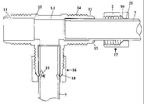
' ~ FIGURE 7 is a section through a T - body and nuts illustrating how a pipe
' ; ~ is fitted according to the present invention ~ . ~ ~ .
3
AMENDED SHEET

S
,. ,
01-03-2003 ~ ' ~ CA 02448249 2003-11-20 ' ZA0~00049-
BEST MODE OF CARRYING OUT TIE INVENTION . . '~
One form of the present invention is a pipe fitting comprising a coupling body
1 shown
in Figure 3 and nut 2 shown in Figure 4. The coupling body I is provided with
an
5~ external thread I4 and a spigot 11 at both ends. A detail of the spigot 11
is shown in
Figure 5. The spigot has a taper 12 having an angle of 70° and a
90° nose section 13.
An internal stop 22 is provided. The end of a pipe to be fitted wilt abut
against the
stop 22 (see Figure 7). .
The nut 2 has a sleeve 20 having axi internal thread 19 which matches the
external
0 0 thread 14 of the coupling body 1. The internal thread 19 commences at one
opening
of the nut ~2 and extends inwardly to a taper 10 near the far erid. 'From the
taper 10 to
the other open end there is a cylindrical section 2I . Instead of a coupling
body 1 a T-
body l .l shown in Figure 6 and having three openings; or even .a cross (not
illustrated)
having four openings maybe used. Each branch has an external thread 14 and
spigot
15 11 with taper 12 and flattened nose 13.
The manner in which the invention operates can be best seen in Figure 7.
A pipe 7 is fed through nut 2 and pushed up against stop 22. ' At 17 a nut is
shown
before it has been screwed onto the T-body 1:1. At 16 the nut is shown.in
compressed
condition i.e. after it has been screwed on and tightened. As the spigot 11
approaches
20 the far end of the nut 2 its taper 12 engages the taper 10 and it is
deflected inwards.
.~ The 90° nose section 13 "bites" into the pipe ? and grips it.
The tapered section 12 on ~fihe spigot 11 may be 70° while the taper 10
on the nut 2 may
be 45°. This an-angement greatly brings down the torque levels required
to tighten the
nut 2. ~ As the nut 2 is tightened the taper I2 deforms against the taper 10
of the nut and
25 ~ takes up a 45° angle against the taper of the nut. As this happens
the sealing effect
takes place and the pipe does not rotate as the nut 2 is being tightened. If
the pipe
needs to be rotated after this, it is necessary first to loosen the nut 2 and
to rotate the
' pipe by hand or with a suitable tool. Due to the 90° nose section the
square section
almost immediately bites into the pipe. ,This also prevents the pipe being
shaved oil
30 by the harder material.
Should a leak occur, there is only one possible direction for water to escape.
This is
along the pipe between the pipe and the. body past the depression I8 on the
pipe and
past the nut 2 as indicated by arrow 15.
4
AMENDED SHEET

..
0'!-'03-2003 '~ CA 02448249 2003-11-20 ~ . ~A0200049
It is also possible to vary the profile of the spigot l l without detracting
'from the .
., invention. For example instead of a taper 12 and a truncated section 13 the
profile may
be a curve (nof illustrated). v..
This feature is a considerable improvement over the earlier invention. A
further
advantage is that there is a considerable saving in material needed to make
pipe fittings
according to this invention when compared to conventional fittings and
fittings
according to the earlier invention.
Lt is to be understood that the nut and body together constitute a pipe
fitting.
1o . '
INDUSTRIAL APPLICATION ~ ~ ' '
' Pipe fittings according to the invention will have countless applications in
the
domestic, industrial, commercial and agricultural sectors.
. '
ao
30
5
AMl=NDl=D SNE~~

Dessin représentatif
Une figure unique qui représente un dessin illustrant l'invention.
États administratifs

2024-08-01 : Dans le cadre de la transition vers les Brevets de nouvelle génération (BNG), la base de données sur les brevets canadiens (BDBC) contient désormais un Historique d'événement plus détaillé, qui reproduit le Journal des événements de notre nouvelle solution interne.

Veuillez noter que les événements débutant par « Inactive : » se réfèrent à des événements qui ne sont plus utilisés dans notre nouvelle solution interne.

Pour une meilleure compréhension de l'état de la demande ou brevet qui figure sur cette page, la rubrique Mise en garde , et les descriptions de Brevet , Historique d'événement , Taxes périodiques et Historique des paiements devraient être consultées.

Historique d'événement

Description Date
Inactive : Regroupement d'agents 2006-08-10
Demande non rétablie avant l'échéance 2006-03-27
Le délai pour l'annulation est expiré 2006-03-27
Réputée abandonnée - omission de répondre à un avis sur les taxes pour le maintien en état 2005-03-29
Inactive : Page couverture publiée 2004-01-30
Inactive : Notice - Entrée phase nat. - Pas de RE 2004-01-27
Inactive : Inventeur supprimé 2004-01-27
Inactive : Regroupement d'agents 2004-01-06
Demande reçue - PCT 2003-12-11
Exigences pour l'entrée dans la phase nationale - jugée conforme 2003-11-20
Demande publiée (accessible au public) 2002-10-10

Historique d'abandonnement

Date d'abandonnement Raison Date de rétablissement
2005-03-29

Taxes périodiques

Le dernier paiement a été reçu le 2004-02-02

Avis : Si le paiement en totalité n'a pas été reçu au plus tard à la date indiquée, une taxe supplémentaire peut être imposée, soit une des taxes suivantes :

  • taxe de rétablissement ;
  • taxe pour paiement en souffrance ; ou
  • taxe additionnelle pour le renversement d'une péremption réputée.

Veuillez vous référer à la page web des taxes sur les brevets de l'OPIC pour voir tous les montants actuels des taxes.

Historique des taxes

Type de taxes Anniversaire Échéance Date payée
Rétablissement (phase nationale) 2003-11-20
Taxe nationale de base - générale 2003-11-20
TM (demande, 2e anniv.) - générale 02 2004-03-26 2004-02-02
Titulaires au dossier

Les titulaires actuels et antérieures au dossier sont affichés en ordre alphabétique.

Titulaires actuels au dossier
HENDRIK VAN WYK
Titulaires antérieures au dossier
S.O.
Les propriétaires antérieurs qui ne figurent pas dans la liste des « Propriétaires au dossier » apparaîtront dans d'autres documents au dossier.
Documents

Pour visionner les fichiers sélectionnés, entrer le code reCAPTCHA :


Pour visualiser une image, cliquer sur un lien dans la colonne description du document. Pour télécharger l'image (les images), cliquer l'une ou plusieurs cases à cocher dans la première colonne et ensuite cliquer sur le bouton "Télécharger sélection en format PDF (archive Zip)" ou le bouton "Télécharger sélection (en un fichier PDF fusionné)".

Liste des documents de brevet publiés et non publiés sur la BDBC .

Si vous avez des difficultés à accéder au contenu, veuillez communiquer avec le Centre de services à la clientèle au 1-866-997-1936, ou envoyer un courriel au Centre de service à la clientèle de l'OPIC.


Description du
Document 
Date
(aaaa-mm-jj) 
Nombre de pages   Taille de l'image (Ko) 
Description 2003-11-20 5 229
Abrégé 2003-11-20 2 62
Revendications 2003-11-20 1 47
Dessins 2003-11-20 4 44
Dessin représentatif 2004-01-30 1 8
Page couverture 2004-01-30 1 40
Rappel de taxe de maintien due 2004-01-27 1 107
Avis d'entree dans la phase nationale 2004-01-27 1 190
Courtoisie - Lettre d'abandon (taxe de maintien en état) 2005-05-24 1 174
PCT 2003-11-20 14 518
Taxes 2004-02-02 1 29