Language selection

Search

Patent 2448420 Summary

Third-party information liability

Some of the information on this Web page has been provided by external sources. The Government of Canada is not responsible for the accuracy, reliability or currency of the information supplied by external sources. Users wishing to rely upon this information should consult directly with the source of the information. Content provided by external sources is not subject to official languages, privacy and accessibility requirements.

Claims and Abstract availability

Any discrepancies in the text and image of the Claims and Abstract are due to differing posting times. Text of the Claims and Abstract are posted:

  • At the time the application is open to public inspection;
  • At the time of issue of the patent (grant).
(12) Patent: (11) CA 2448420
(54) English Title: ERGONOMIC KEYBOARD TILTED FORWARD WITH NON-QWERTY KEY LAYOUT
(54) French Title: CLAVIER ERGONOMIQUE INCLINE EN AVANT AVEC DISPOSITION NON-QWERTY DES FONCTIONS DE TOUCHES
Status: Deemed expired
Bibliographic Data
(51) International Patent Classification (IPC):
  • B41J 5/10 (2006.01)
  • G06F 3/023 (2006.01)
(72) Inventors :
  • MANDEL, YARON NAHUM (Canada)
(73) Owners :
  • MANDEL, YARON NAHUM (Canada)
(71) Applicants :
  • MANDEL, YARON NAHUM (Canada)
(74) Agent: NA
(74) Associate agent: NA
(45) Issued: 2006-01-17
(22) Filed Date: 2003-11-07
(41) Open to Public Inspection: 2004-06-10
Examination requested: 2003-11-07
Availability of licence: N/A
(25) Language of filing: English

Patent Cooperation Treaty (PCT): No

(30) Application Priority Data:
Application No. Country/Territory Date
10/315,212 United States of America 2002-12-10

Abstracts

English Abstract


An ergonomic keyboard having a Dvorak key layout. The keys are arranged in a V
or U shape.
The keyboard is tilted downward away from the user. The keyboard has a wrist
rest, and a switch
to change the key layout to QWERTY.


Claims

Note: Claims are shown in the official language in which they were submitted.


CLAIMS
The embodiments of the invention in which an exclusive property or privilege
is claimed are
defined as follows:
1. An ergonomic keyboard comprising
an upper row of character keys comprising from left to right P Y F G C R L,
a middle row of character keys comprising from left to right A O E U I D H T N
S,
and a lower row of character keys comprising from left to right Q J K X B M W
V Z;
said keyboard further comprising other keys;
said keyboard is tilted away from the user, such that the rows of keys nearer
to the user are higher
than the rows of keys farther from the user.
2. The keyboard in claim 1, wherein said rows of character keys lie along a V
or U shape.
3. The keyboard in claim 1, wherein said rows of character keys are split into
two groups lying
along the two sides of a V or U shape,
the left side of said upper row comprising from left to right P Y,
the right side of said upper row comprising from left to right F G C R L,
the left side of said middle row comprising from left to right A O E U I,
the right side of said middle row comprising from left to right D H T N S,
the left side of said lower row comprising from left to right Q J K X, and
the right side of said lower row comprising from left to right B M W V Z.
4. The keyboard in claim 1, wherein said keyboard further comprising a wrist
rest.


5. The keyboard in claim 1, wherein the side profile of said keyboard is
concave.
6. The keyboard in claim 1, wherein the side profile of said keyboard is
convex.
7. The keyboard in claim 1, wherein said keyboard further comprising a switch
changing the key
configuration to QWERTY.

Description

Note: Descriptions are shown in the official language in which they were submitted.


CA 02448420 2005-08-29
ERGONOMIC KEYBOARD TILTED FORWARD WITH NON-QWERTY KEY LAYOUT
The invention relates to ergonomic keyboards for computers and terminals.
In an effort to minimize repetitive strain injuries ( RSI ) such as carpal
tunnel syndrome,
keyboard manufacturers have turned their attention to ergonomic keyboards.
Several approaches
have been used.
One approach involves arranging the keys along a flat V or U shape instead of
a straight
horizontal line. The keys are arranged either in one continuous group along
this shape, or in two
groups. The advantage is that the angle of the user's arms is more natural and
therefore more
relaxed. Sometimes the keyboard also has a wrist rest. For example, see
Camacho ( US patent
6,467,979 and others ).
Another approach involves the use of the Dvorak key layout ( ANSI standard
X3.207 ) instead of
the more common QWERTY key layout. The advantage is that the most commonly
used keys are
located on the home row, which minimizes forger travel and extension. For
example, see
Zagnoev ( US patent 5,936,555 ).
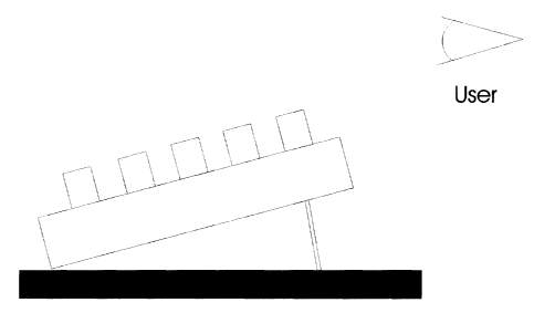
Another approach involves placing the keys below the level of the user's palm,
or tilted
downwards away from the user. This is instead of the usual arrangement where
the keyboard is
either tilted upwards away from the user, or it is flat on the desk. The
advantage is that the user's
palm slopes downwards along the surface of the keys, so it continues along the
line formed by
1


CA 02448420 2003-11-07
the user's arm from the shoulder downwards. Therefore the user's palm is more
relaxed. For
example, see Hargreaves ( US patent 6,005,496 and others ).
All these approaches are beneficial. Some of the prior art combines a number
of approaches to
improve the keyboard. It would be best to combine all of these approaches.
SUMMARY
This invention combines the three approaches described in the prior art
section to create an
ergonomic keyboard. The keyboard has a Dvorak key layout. It is tilted
downwards away from
the user. The keys are arranged in a V or U shape. It has a wrist rest. The
result is a superior
ergonomic keyboard that helps minimize repetitive strain injuries.
DRAWING FIGURES
Fig. 1: The keyboard with the character keys arranged in 2 groups in a V
shape.
Fig. 2: Side view of the keyboard without a wrist rest.
Fig. 3: Side view of the keyboard with a wrist rest.
Fig. 4: Side view of the keyboard with a different kind of wrist rest.
Fig. 5: Side view of the keyboard with a concave profile and with a wrist
rest.
2


CA 02448420 2003-11-07
DETAILED DESCRIPTION
This keyboard combines a number of ergonomic features.
The keyboard uses the Dvorak key layout instead of the usual QWERTY. The keys
are arranged
in a V or U shape. Fig. 1 shows the character keys arranged in two groups to
form a V shape. The
keys can also be arranged in one group and in a U shape.
The Dvorak key layout can be split in two groups using the groups as shown in
fig. 1, or split in
two different groups. Only character keys are shown. Other keys such as
numeric, punctuation,
arrow and function keys are not shown. Placement of these keys will vary in
different
implementations. The implementations do not necessarily adhere to ANSI
standard X3.207.
The preferred embodiment of the keyboard has character keys in the layout
shown in fig. 1. Fig. 1
shows the keys arranged in straight rows and columns. This is not necessarily
the case. In most
implementations the columns will not be vertical as shown. For example, S will
not generally be
straight above Z, and E will not be exactly above J.
The keyboard is tilted downward away from the user. See fig. 2. This is
different from the usual
keyboard which is either flat on the desk, or is tilted upward away from the
user.
The keyboard has a wrist rest. Fig. 3 and fig. 4 show two different wrist
rests. Other positions for
the wrist rest are also possible. For example, a horizontal wrist rest such as
the one in fig. 4 can
3


CA 02448420 2003-11-07
be used, but it can be located higher, at a longer distance from the keys. The
preferred
embodiment has a horizontal wrist rest generally as shown in fig. 4, but it
can be located higher,
at a longer distance from the keys.
The keyboard can be curved: concave or convex. Fig. 5 is a concave keyboard
with a wrist rest.
The keyboard has a switch that changes the key configuration from Dvorak to
QWERTY.
The foregoing description of the preferred embodiment of the invention and
some possible
variations has been presented for the purposes of illustration and
description. It is not intended to
be exhaustive or to limit the invention to the precise form disclosed. Many
modifications and
variations are possible. It is intended that the scope of the invention be
limited not by this
detailed description, but rather by the claims appended hereto.
4
Representative Drawing
A single figure which represents the drawing illustrating the invention.
Administrative Status

For a clearer understanding of the status of the application/patent presented on this page, the site Disclaimer , as well as the definitions for Patent , Administrative Status , Maintenance Fee  and Payment History  should be consulted.

Administrative Status

Title Date
Forecasted Issue Date 2006-01-17
(22) Filed 2003-11-07
Examination Requested 2003-11-07
(41) Open to Public Inspection 2004-06-10
(45) Issued 2006-01-17
Deemed Expired 2008-11-07

Abandonment History

There is no abandonment history.

Payment History

Fee Type Anniversary Year Due Date Amount Paid Paid Date
Request for Examination $200.00 2003-11-07
Application Fee $150.00 2003-11-07
Maintenance Fee - Application - New Act 2 2005-11-07 $50.00 2005-11-02
Final Fee $150.00 2005-11-07
Maintenance Fee - Patent - New Act 3 2006-11-07 $50.00 2006-10-30
Owners on Record

Note: Records showing the ownership history in alphabetical order.

Current Owners on Record
MANDEL, YARON NAHUM
Past Owners on Record
None
Past Owners that do not appear in the "Owners on Record" listing will appear in other documentation within the application.
Documents

To view selected files, please enter reCAPTCHA code :


To view images, click a link in the Document Description column. To download the documents, select one or more checkboxes in the first column and then click the "Download Selected in PDF format (Zip Archive)" or the "Download Selected as Single PDF" button.

List of published and non-published patent-specific documents on the CPD .

If you have any difficulty accessing content, you can call the Client Service Centre at 1-866-997-1936 or send them an e-mail at CIPO Client Service Centre.


Document
Description 
Date
(yyyy-mm-dd) 
Number of pages   Size of Image (KB) 
Representative Drawing 2004-01-09 1 5
Claims 2004-07-29 2 42
Claims 2005-05-18 2 37
Abstract 2003-11-07 1 7
Description 2003-11-07 4 112
Claims 2003-11-07 2 37
Drawings 2003-11-07 3 44
Cover Page 2004-05-14 1 26
Claims 2004-12-13 2 41
Description 2005-08-29 4 114
Cover Page 2005-12-19 1 27
Prosecution-Amendment 2004-02-09 3 85
Prosecution-Amendment 2004-07-29 8 166
Correspondence 2003-12-12 1 11
Assignment 2003-11-07 2 75
Prosecution-Amendment 2004-12-01 2 42
Prosecution-Amendment 2004-12-13 3 67
Correspondence 2005-04-19 1 19
Correspondence 2005-05-18 3 60
Correspondence 2005-07-12 1 20
Correspondence 2005-08-29 2 62
Correspondence 2005-11-07 1 22
Prosecution Correspondence 2003-11-07 10 1,047