Note: Descriptions are shown in the official language in which they were submitted.
CA 02448451 2003-11-20
1
TURBOCHARGED INTERNAL COMBUSTION ENGINE
This is a divisional of copending Canadian Patent
Application Serial No. 2,124,264 filed on May 25, 1994.
BACKGROUND OF THE INVENTION
This invention relates to supercharged internal combustion
engines.
The practice of supercharging internal combustion engines
by means of turbochargers to improve their power output is well
known in the art.
Each turbocharger normally comprises a turbine rotor and a
compressor rotor mounted coaxially on the same shaft, the
turbine being driven by the energy present in the exhaust gases
from the reciprocating internal combustion engine and the
compressor serving to compress air for delivery to the engine.
In one particular type of turbocharger, employed in an
embodiment of the invention to be described later, there are
three major functional sections. The central section consists
of a housing which carries the bearing system for supporting a
rotor consisting of a shaft with, at one end a centrifugal
compressor impeller, and at the other end the rotor of a
radial-flow turbine. The compressor end of the bearing housing
carries a circular flange to which is attached the compressor
casing of the centrifugal compressor.
At the opposite end of the bearing housing there is
associated with the turbine rotor a turbine casing into which
exhaust gas is conducted from the engine. The casing serves to
shape the flow of the hot gases before their expansion through
the turbine rotor.
The gases entering the turbine casing are generally hot,
CA 02448451 2003-11-20
2
with temperatures up to 700°C not being uncommon, and it is
therefore an advantage to the bearings if the turbine casing
can be supported as independently as possible of the bearing
housing, thereby to reduce heat flow from the turbine casing
into the bearing housing.
The bearing housing requires a supply of cool oil to
lubricate the bearings supporting the rotor and a drain means
to take the used oil away.
A conventional method of support for turbochargers is to
support a turbocharger via a flange attached to the~inlet of
the turbine casing. Whilst this may be simple it means that
a considerable dead load is applied to the exhaust ducting
which conveys the exhaust gases from the engine to the
turbocharger.
It is also known to support turbochargers via a flange
attached to the outlet of the turbine housing, which gives
rise to similar problems regarding deadload. It is also known
to support turbochargers by a support bracket coupled to the
central section.
For single-stage turbocharging it may be sufficient to
use a single supercharger. For larger engines, in particular
those having two rows of cylinders; each row of cylinders may
be provided with its own supercharger. An example of such an
arrangement is disclosed in United Kingdom Patent GB43709'8:~
The pressure ratio obtainable by a single stage
turbocharger is somewhat limited, and for higher performance,
multipie stage turbocharging has been employed, the required
degree of compression being provided by disposing a high
pressure turbocharger in series with a low pressure
3S turbocharger. Exhaust gas from the engine first passes
through the turbine of the high pressure turbocharger and then
passes through the turbine of the low pressure turbocharger.
CA 02448451 2003-11-20
3
Similarly, air at atmospheric pressure is first compressed in
the low pressure compressor and is then further compressed in
the high pressure compressor.
However, this does give rise to problems. The turbines
get very hot in use and as a consequence their turbine casings
and associated exhaust duct work are subject to thermal
expansion when starting from cold. This gives rise to
problems in maintaining the exhaust duct work gas-tight. This
can be a problem where engines are installed in confined
spaces such as ships or basements of buildings.
To overcome the problems of exhaust gas leakage it has
been proposed .to construct a two-stage turbocharger with a
unitary combined casing for the high and low pressure
turbines. Such arrangements are disclosed in US Patent
4032262 (Zehnder), and US patent 4196593 (Froeliger) and
involve the provision of a unitary casing for the high and low
pressure turbocharger.
Where two-stage turbocharging is applied to large
engines, the low pressure turbocharger may prove to be
physically large such that mounting on the engine,is not
practical. The low pressure:turbocharger then whas to be
mounted off the engine and coupled thereto by ducting. Such
an arrangement is disclosed in the publication "Shipbuilding
and Marine Engineering International" April 1977 page 171 and
the article "Development of two-stage turbocharging system on
a four stroke medium speed diesel engine" CIMAC, 12th
International Congress on Combustion Engine, Tokyo 1977 paper
A7 Fig 16. Such arrangements require considerable headroom
and present difficulties where an engine is. to be installed
in a confined space having limited headroom.
It is sometimes the practice not .to cool the turbine
casings, inter alia because condensation of combustion
products on a cooled turbine casing has been found to lead to
CA 02448451 2003-11-20
4
corrosion and consequent reduction in service life. This has
exacerbated the problems of thermal expansion. Further, the
elimination of cooling from the turbine housing leads to
increased heat loss from the engine. This can be a problem
in confined spaces.
An alternative method of supporting the turbocharger is
known from US 4400945 (Deutchmann).
US Patent 4400945 (Deutchmann) provides a housing to
which turbochargers are mounted such that the turbines and
their associated conduits are disposed within the'housing,
while the compressors and their associated conduits are
outside the housing. The housing may be sealed to prevent
escape of any exhaust gas which might leak pass the joints in
the exhaust conduits.
Deutchmann teaches to arrange.the bearing housing to be
supported by a box-like enclosure surrounding the turbine
casing. The enclosure is split along a plane passing through
the centre-line.of the bearing housing, and the two halves of
the enclosure are arranged to tighten down onto the bearing
housing, this being achieved by arranging 'the bearing housing
to be of cylindrical shape, and the wall of the enclosure to
have an accommodating circular hole equally displaced about
the split-line. If the enclosure's grip on the turbocharger
. is to be secure and stable, then the beaxing housing diameter
and the internal diameter of the hole in the enclosure have
to be manufactured to fine limits. With this arrangement,
the turbocharger can only be removed by dismantling the
enclosure to some degree, and, where a sealed housing is
employed, the joints between the 'two halves of the housing
along the dividing plane and around the turbochargers have to
be re-sealed, and the connections between the top of the
35. housing~and any other components, such as the exhaust pipe,
which had to be disconnected before the top of the housing
could be removed, must be re-connected and re-sealed.
CA 02448451 2003-11-20
Deutchmann also mitigates the problem of headroom by the
provision of a relatively large number of individual relatively
small turbochargers or two-stage turbocharger assemblies rather
than one or two relatively large turbochargers. However, the
5 low pressure turbochargers of Deutchmann's two-stage
turbochargers are physically larger than their associated high
pressure turbochargers.
CA 02448451 2003-11-20
6
SUMMARY OF THE INVENTION
In accordance with one aspect of the present invention
there is provided a supercharged internal combustion engine
comprising a turbocharger, said turbocharger comprising a
turbine housing, a compressor housing, and a cartridge
comprising a shaft and bearings for said shaft, said shaft
carrying a turbine rotor and a compressor impeller, a wall
adapted to support said turbocharger on said engine, said wall
having a first side and a second side opposite said first side
and an aperture extending through said wall between said first
and second sides wherein said turbine housing is adapted to be
secured to said first side about said aperture, said cartridge
being designed so that, during assembly it can be inserted
through said aperture thereby aligning said turbine rotor
within said turbine housing and said cartridge being adapted to
be secured to said second side about said aperture, said
compressor housing being adapted to be secured to said
cartridge to align said compressor impeller with said
compressor housing.
CA 02448451 2003-11-20
7
BRIEF DESCRIPTION OF THE DRAWINGS
In the drawings
Figure 1 shows a plan view of an engine' in accordance
. with the invention;
Figure 2 shows a cross-section of Figure 1 on II - II;
Figure 3 shows a plan view of a turbocharger assembly
of Figure 1 on III - III;
Figure 4 shows a cross-section of Figure 3 on IV - IV;
CA 02448451 2003-11-20
8
Figure 5 shows a cross-section of Figure 3 on V - V
illustrating a turbocharger; and
Figures 6 to 9 show the steps of assembling the
turbocharger of Figure 5.
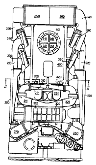
In Figure 1 air inlet ports 200, 201 are connected via
conduits 210, 220 to the inlet ports of respective pairs of
low-pressure compressors 330, 340 and 350, 360. The pairs of
compressors are mounted on the outer surfaces of side walls
of an enclosure 400. The compressors are driven by turbine's
disposed within enclosure 400 as will be described later: The
output ports of the compressors 330, 340 and 350, 360 are
respectively connected via in parallel by respective ducts
230, 24.0 to respective intercoolers 250, 260. The cooled air
is fed over ducts 251, 261 to respective inputs of high
pressure compressors 310, 320 mounted on an outer end wall of
enclosure 4a0. The output ports of the high pressure
compressors 310, 320 are coupled via ducts 311, 321 to
respective aftercoolers 312, 322. The outputs of the
aftercoole~s 312, 322 are connected via conduits 270, 280 to
respective inlet manifolds, not shown. enclosure 400 liar a
flange 401'adapted.to receive an exhaust pipe, not shown, for
conveying exhaust gas to the atmosphere as will be described
later. Exhaust gas from the turbines disposed within
enclosure 400 is fed into the exhaust pipe via respective
trumpets 331, 341, 351, 361 as will be described later.
In Figure 2 air inlets 200, 201 and their associated
ducts 210, 220 have been omitted for clarity. Pistons 1, 2
are coupled via connecting rods 3, 4 to crankshaft 5 in
conventional manner. Inlet valves 6, 7 allow air from inlet
manifolds 271; 281 to. be admitted to cylinders 1.0, 11 during
the induction stroke of the engine. The conventional fuel
injecting arrangements and valve gear have been omitted for
CA 02448451 2003-11-20
9
clarity. Exhaust gas from the cylinders is led via exhaust
valves 8, 9 to respective exhaust manifolds 12, 13 and thence
to the inlet ports of respective high pressure turbines 31,
32. Turbines 31, 32 are mounted on the walls of enclosure 400
as will be described later. Conduits 251, 261 bring cooled
air from the intercoolers to the inlets of the high pressure
compressors.
The exhaust manifolds 12, 13 are surrounded by respective
water cooled jackets 120, 130. The interiors of these jackets
communicate with the interior 405 of the enclosure 400 such
that any exhaust gas leaking from the exhaust manifold joints
can escape via enclosure 400 as will be described later.
Referring to Figure 3, the side walls 300 of enclosure
400 are hollow to allow coolant to be passed therethrough.
The high pressure compressors 310, 320 are coupled to
respective high pressure tuxbines 31, 32, and the pairs of low
pressure compressors 330, 340 and 350, 360 are coupled to
respective pairs of low pressure turbines 33, 34 and 35, 36.
The output ports of high pressure turbines 31, 32 are
connected via conduits 312, 313 and 322, 323 to the inlet
ports of low-pressure turbines 33, 34 and 35, 36. Exhaust gas
from the outlet ports of the low pressure turbines is fed via
trumpets 331; 341, 351, 361 to an exhaust pipe, not shown, as
will be described later. The connections between the output
ports of the high pressure turbines 31 , 32 and the ducts 312,
322 are made via respective expansion joints 420, X50:
Expansion joints 440, 470 are also provided in conduits 313,
323.
Referring to Figure 4, the high pressure turbocharger 31,
310 is mounted in a wall 700 of enclosure 400 as will be
described later. Trumpets 331, 341 direct exhaust gas from
the low pressure turbines 33, 34 into exhaust pipe 410 but are
not sealed relative to the walls of the exhaust pipe. The
enclosure 400 has a lid 415. The exhaust pipe 410 is sealed
CA 02448451 2003-11-20
relative to the lid 415 at a connection flange 401 using
fasteners, not shown, such that the interior 405 of the
enclosure 400 communicates with the interior of the exhaust
pipe 410, and any exhaust gas leaking from joints 420, 430;
5 440, or from the exhaust manifold as referred to earlier,
passes into the interior 405 of the enclosure 400 and is free
to escape therefrom via the exhaust gipe 410 and does not
result in pressuxe building up within enclosure 400.
10 The construction of the turbachargers will now be
described with reference to Figures 5 to 9.
The turbocharger comprises four principal components.
These are
(a) a turbine housing 500
(b) a compressor housing 510
(c) a cartridge 600 comprising the moving parts of the
turbocharger; and
(da an intezmediate-portion 750 of the wall 700 of the
housing 400.
Referring to Figure 5, the cartridge 600 comprises a
compressor impeller 512 and a turbine rotor 504 mounted on a
common shaft 506 running in bearings 509. The cartridge 600
has oilways 311 adapted to supply lubricating oil to the
bearings 509 and an oil drain duct 312 for oil emerging from
the bearings 509. The oilways 311 and duct 312 terminate in
an axial face 507 of the cartridge 600. A heat shield 630
shields the bearings from hot exhaust gases in the turbine in
known manner. The housing wall 700 has an oil feed conduit
702 terminating at a first face 703 of the wall 700 and
arranged to communicate with the oilway 311 in the cartridge
600 when the cartridge is assembled to the first face 703 as
CA 02448451 2003-11-20
11
will be described later. The wall 700 also has an oil drain
duct 704 terminating at the first face 703 and arranged to
communicate with the oil drain duct 312. The housing has "0"
ring oil seals 705, 706 adapted to 'seal the oilways and oil
drain.
Referring to Figures 6-9, to assemble.the turbocharger,
the turbine housing 500 is aligned with a bore 751 in a
support region 750 of the wall 700 using an arbor (not shown)
or by making registers in the wall and the turbine housing.
The turbine housing 500 is secured in position with fasteners
610 engaging tapped holes 616 in the turbine casing 500 and
washers 612. On tightening the fasteners, axial face 520 of
turbine casing 500, is drawn tightly against a first face 707
of region 750. The faces 520 and 707 are machined to provide
a gas-tight join therebetween when the faces are drawn
together. Next the cartridge 600 is inserted into the bore
752. The region 750 has a second face 703 adapted to engage
with the axial face 507 of the cartridge 600. The thickness
of the region 750 is such that, as shown in Figure 8, when the
face 507 engages face ?03, the turbine rotor 504 is correctly
disposed with respect to the turbine housing 500. The
cartridge;is held concentric with the turbine casing by a
spigot 670 having a close fit in a narrow. circular register
5?0 in the turbine housing 500. The cartridge 600 is secured
to the second face by fasteners 620 and washers 622 which
engage tapped holes 624 in the region 750 as shown in Figure
8. On tightening the fasteners 620, the 'O' ring seals 705,
706 (Figure 5 ) are compressed to seal the oil feed and the oil
drain connections.
Finally the compressor housing 510 is assembled to the
cartridge 600 as shown in Figure 9, and secured in place by
means of a vee-section clamping ring 54. This allows the
radial orientation of the housing 510 to be adjusted so as to
bring the compressor outlet port 503 to any desired position.
CA 02448451 2003-11-20
12
It will be seen that, on completion of the assembly, the
region 750 becomes an integrated part of the turbocharger
assembly; its thickness determining .the alignment of the
turbine rotor relative to the turbine housing.
It can be seen that, should a turbocharger become faulty in
service, to replace the cartridge 600 carrying the moving
parts it is only necessary to disconnect the air.outhet 503,
remove clamp 54, pull off the compressor casing 510, release
the fasteners 620 and withdraw the cartridge 600. A
replacement cartridge can then be refitted in the manner
described previously: It is not necessary to disturb the
turbine housing 500 or the exhaust conduits coupled to the
turbine inlet or outlet parts, and; when the turbine is
mounted in a sealed enclosure, the integrity of the sealing
of the enclosure is not broken. This affords a much simpler
and faster turbine servicing than the prior art arrangement
referred to above in which the housing must be split and the
cpper part of the housing removed and they replaced and re
sealed to replace a faulty turbocharger.
The arrangement thus described offers a number of
advantageous features. By providing two low-pressure
turbochargers in series with one high pressure turbocharger,
it is possible for all the turbochargers to be substantially
identical.
Further, while the interior of the enclosure is at a
pressure which is higher than that of the engine surroundings,
this pressure is only of the order of that of the exhaust
gases leaving the low pressure turbine, as gas leaking from
the conduits coupled to the high pressure turbines would
escape via the exhaust pipe and will not cause pressure build
up within the housing. If the interior of the housing were
35. hermetically sealed and a leak developed at the inlet of the
high pressure turbocharger, then the pressure within the
housing could rise to that value. Providing conanunication
CA 02448451 2003-11-20
13
between the interior of the housing and the exhaust pipe
avoids subjecting the housing to high pressures, thereby
avoiding problems with sealing which might otherwise arise.
Attaching the turbine housing directly to the wall of the
casing provides significant advantages in heat transfer, as
much of the heat transferred from the exhaust gases to the
turbine casing is diverted away from the bearings and flows
directly.to the wall whence it can be removed via the coolant
therein. In the known turbochargers, heat from the hot
turbine housing flows via that portion of the turbocharger
housing intermediate the turbine and the compressor to cooler
regions and, should an engine have to be suddenly shut down
and as a consequence the oil pump providing forced lubrication
(and cooling) of the turbocharger bearings ceases to operate,
the high thermal gradient between the turbine casing (which
can be at red heat) and the cooler regions can be such as. to
cause carbonization of the lubricating oil in the bearings.
In the turbocharger described above, the relatively
narrow annular region where the spigot 670 mates with the
register 570 is the only significant region where direct
mechanical contact offering a low thermal resistance exits
between the hot turbine easing 500 and the. cartridge 600
containing the bearings. The air gap associated with the
relatively loose fit between the other regions provides an
increased thermal resistance to heat flow by conduction.
Further, the direct connection between the turbine casing 500
and the wall 700, which, as noted may be hollow to accommodate
coolant, is via mating surfaces 570 and 707 which have been
machined to provide a good mechanical fit, and which therefore
provide a low thermal resistance path to heat flow by
conduction, which path shunts heat away from the bearings
within cartridge 600.
By providing two low-pressure turbines in parallel, each
CA 02448451 2003-11-20
14
handling half the volume of gas emanating from a single high
pressure turbine, it is possible to arrange for the high
pressure and low pressure turbines to be substantially
identical. This results in economics in manufacture, and
reduces the number of types of spare parts required for
servicing. However, the provision of a common turbine design
for both high and low pressure turbines may result in a slight
reduction in energy efficiency compared with optimising the
design for high and low pressure turbines individually.
Accordingly it may be advantageous in the terms of
operating efficiency for the turbine housing of 'the high
pressure turbocharger to be somewhat different from that of
the low pressure turbocharger, but for a common turbine rotor
to be used for both the high and low pressure turbines. This
arrangement has been utilised by applicants, and was found to
be advantageous in that in general, the turbine housings
seldom need attention and will remain in position on the wall,
while the cartridge comprising the turbine rotor and
compressor impeller and associated bearings, which constitutes
the moving parts of the turbocharger, is readily removable and
replaceable. Such an arrangement allows a ;common cartridge
to be used for both the high and_low pressure turbochargers
and provides satisfactory operational efficiency.
While Applicants found that the use of a common
compressor housing and a common cartridge comprising
compressor impeller and turbine rotor for both the high and
low-pressure tuxbocharger gave satisfactory results, this is
not essential. It maybe that for certain applications the
high-pressure turbocharger needs to be different from the low-
pressure turbochargers in order to attain optimum efficiency.
Such an arrangement in accordance with the invention will
still offer advantages over a conventional two-stage
turbocharger comprising one relatively small high-pressure and
one relatively large low-pressure turbocharger, as the height
of each low-pressure turbocharger will be less than that of
CA 02448451 2003-11-20
a single low-pressure turbocharger of corresponding capacity.
This reduction in height can be advantageous where an engine
is to be installed in a location having limited headroom.
Also, the lighter weight of the individual low-pressure
5 turbochargers in accordance with the invention as compared
with the greater weight of a single large low-pressure
turbocharger facilitates removal and installation in locations
where access is difficult and heavy lifting gear is not
readily deployable.