Note: Descriptions are shown in the official language in which they were submitted.
CA 02448573 2010-03-02
1
APPARATUS FOR TREATMENT WITH MAGNETIC FIELDS
Description
Field of the invention
The invention relates to an apparatus and a method for
treatment with magnetic fields in general, and to the
influencing of spins and/or magnetic moments in tissue to
be treated, in particular.
Background of the invention
Non-invasive treatment methods are finding ever more new
fields of application in the medicine. With respect to
the invention registered here, apparatuses and methods
for therapeutic treatment by means of external magnetic
fields should be mentioned in particular. Even though,
until now, the precise mechanism of operation of such
therapies has not been understood in detail, their
therapeutic success has been scientifically proven and is
generally recognized. Investigations into the results of
known magnetic field therapies can be found, for example,
in "Orthapadische Praxis" 8/2000, [Orthopedic practice]
year 36, pages 510 to 515 and in Fritz Lechner,
"Elektrostimulation und Magnetfeldtherapie. Anwendung,
Ergebnisse und Qualitatssicherung" 1989
["Electrostimulation and magnetic field therapy. Use,
results and quality assurance"].
CA 02448573 2003-11-25
2
In particular, it has been found in investigations such as
these that magnetic field therapies applied to patients in
some cases produce considerable improvements in the signs and
symptoms without significant negative side effects that can
be verified. A further major advantage of magnetic field
therapies is that an operation which is associated with
considerable pain, risks and costs for the patient may
possibly be completely avoided.
Thus, for example, EP 0 661 079 Al discloses a magnetic field
therapy appliance having a large number of magnetic field
generators.
The document EP 0 392 626 A2 likewise describes an appliance
for magnetic field therapy. This appliance contains a large
number of coils, which are arranged such that the magnetic
fields are as far as possible not superimposed, in order to
achieve a relatively homogeneous field.
The two apparatuses which are described in the documents EP 0
661 079 Al and EP 0 392 626 A2 accordingly relate to
apparatuses which attempt to bring about a successful
treatment by the direct effect of the magnetic field.
Furthermore, DE 40 26 173 discloses an apparatus which
produces pulsed and modulated magnetic fields in order to
treat patients. In this case, body tissue is subjected to a
magnetic field which is produced by superimposition of a
constant magnetic field and a magnetic alternating field.
Pulsed magnetic fields are typically produced by means of a
pulsed current, which flows through a coil. However, pulsed
fields such as these in coils require a large amount of
energy and have a high degree of inertia since the coil
inductance slows down the rate of change of the field.
CA 02448573 2003-11-25
3
The healing effect of this magnetic field therapy comprises,
inter alia, the relief of osteoporosis and the consequences
of a stroke. In this, it appears to be probable that the
magnetic fields which are applied promote transport and/or
metabolism processes which lead to a positive therapeutic
effect. Until now, it has been assumed that the positive
therapeutic effect is caused by an energy interchange between
fields and components of cells (protons, ions etc.). In this
case, the energy transfer has been explained by the
stimulation and/or absorption of ion-cyclotron resonances
(ICR) in a biological body, and appropriate, ICR conditions
are thus looked for. The known apparatuses are consequently
based on production of ICR conditions.
However, this causal explanation appears to be questionable
in some circumstances, since cyclotron resonances generally
occur only on free particles, for example in a vacuum or in
the case of electrons in the conductance band of a
semiconductor. Furthermore, simple calculation can also be
used to show that a cyclotron movement will be carried out on
an orbit whose radius is intrinsically greater than the
average diameter of a cross section of a human body. This
means that an explanation with regard to energy transfer for
cyclotron resonance may be questionable, particularly for
solid tissue.
It is also possible for the effect to be based on
piezoelectric processes in the body. This explanation
approach is based on the assumption that there is an
electrical field around every body joint and, in the healthy
state, every movement causes a piezo voltage, since the
cartilage has piezoelectric characteristics. In the unhealthy
state, these piezo voltages could be simulated by induced
voltages. In this context, see also Christian Thuile, "Das
CA 02448573 2003-11-25
4
grof3e Buch der Magnetfeldtherapie", Linz 1997. (The Big Book
on magnetic field therapy].
A further apparatus for treatment of a biological body with
magnetic fields, which produces spin resonances within the
body to be treated, is disclosed in Laid-Open Specification
WO 99/66986 from the same applicant. This apparatus as
described in Laid-Open Specification WO 99/66986 is, however,
essentially based on carrying out specific reproducible
treatment with magnetic fields in all biological materials,
irrespective of whether any ionic parts are present. The
cited apparatus achieves the positive therapeutic effects by
production of spin resonances and spin resonance sequences.
In this case, the nuclear magnetic resonance is, however,
also used in particular for energy transfer.
In other fields of technology, nuclear magnetic resonance
methods (so-called NMR methods) have already been known for a
long time. They are used in particular for medical diagnosis
and in general for the high-precision magnetic field
measurement. With regard to the latter application, reference
should be made, for example, to the "Virginia Scientific
FW101 Flowing Water NMR Teslameter". A description of this
appliance can be found at
www.gmw.com/magnetic-measurementsNSI/FW101.html.
It should also be stated that the known apparatuses for
therapeutic medicine generally comprise large coil systems
with which the magnetic fields are generated and varied.
However, these coil systems have a high inductance, which
leads to long switching time constants and to consumption of
a large amount of energy. Long switching times
disadvantageously lead, however, to poor efficiency with
regard to dynamic processes in the body.
CA 02448573 2003-11-25
Furthermore, the coil systems are typically designed such
that they have openings into which body parts, for example,
arms or legs, can be inserted. In consequence, the known
5 apparatuses are relatively shapeless and have disadvantages
with regard to the possible ways to store them and transport
them. Apart from this, in some cases, they are not convenient
for the patient. Furthermore, the energy required for the
most known apparatuses is very high, since the coil systems
produce strong magnetic fields.
In addition, there are still a number of open questions with
regard to the physical-physiological way in which the
apparatuses operate and with regard to the processes which
are initiated by them in the body. However, in the past,
without any detailed knowledge of the way in which they
operate, an optimized design and the optimum parameters for
its operation could be determined only with difficulty.
One object of the present invention is thus to provide an
improved apparatus and an improved method for treatment with
magnetic fields.
A further object of the invention is to make an apparatus and
a method available by means of which electromagnetic stimuli
which are produced by movement in the body, in particular the
natural behavior of magnetic moments in the body can be
modeled or simulated artificially during movement in the
earth's magnetic field.
Another object of the invention is to make available an
apparatus and a method which allow short switching time
constants and consume little energy.
CA 02448573 2010-03-02
6
A further object of the invention is to make available an
apparatus for treatment with magnetic fields, which can
be transported and stored easily, is convenient for the
patient and, in particular, can also be manufactured at
low cost.
The invention is based on the extremely highly surprising
knowledge that positive therapeutic effects from
treatment with magnetic fields can be traced back to
movement simulation via spin resonance signals.
Magnetic moments, for example electron and nuclear spin
moments can be aligned just in the earth's magnetic field
in a human, animal or other biological body, and thus
produce macroscopic magnetization. Any movement of a
body part leads to a small change in the direction of
this magnetization. Provided that the magnetization
direction is not aligned parallel to the earth's magnetic
field direction, the magnetization precesses at a
frequency of about 2000 Hz in the earth's magnetic field,
and induces an alternating voltage at the same frequency
in the environment. This induced voltage can be measured
using an external coil, and is in the milli volt range.
However, the induced voltage in the body is considerably
greater since the distances are shorter. The human
nervous system registers this voltage and thus identifies
the movement. In consequence, the metabolism is
activated since energy is required for muscular work.
Various debilitations restrict the movement of a patient
and his or her metabolism. The apparatus according to
the invention and the method result in predetermined and
CA 02448573 2003-11-25
7
deliberate rotation of the spins and of the macroscopic
tissue magnetization that is produced by the spins. With
regard to the spin resonances which are produced naturally by
the earth's magnetic field in the body, the organism is made
to believe that movement has taken place, which has not taken
place in reality. To do this, the apparatus according to the
invention produces suitable magnetic fields which vary the
alignment of the spins and/or of the magnetization in such a
way that this simulates a movement of the body area which is
arranged in the treatment area. In this context, it has been
possible, inter alia, by the use of the present invention, to
achieve very good treatment success in the therapy for
osteoporosis.
A first embodiment of the invention is distinguished in that
the apparatus according to the invention for treatment with
magnetic fields comprises a first and a second device for
production of a first and a second magnetic field,
respectively, and a mount, in particular a mat for body areas
of a patient to be treated, or the entire patient, to rest on
and/or against. In this case, the mount, such as the mat
defines an upper face and a lower face, between which the
first and second devices for production of the first and
second magnetic fields, respectively, are preferably
arranged. This arrangement allows a very compact, in
particular very flat, configuration.
In addition to a mat in which the devices for production of
the first and second magnetic fields are arranged, a
treatment couch or a treatment stool may also be used as the
mount. In addition, systems are possible which are placed on
the patient, or on the tissue to be treated. By way of
example, the mount may comprise a multi-winged arrangement
which can be placed around a body part, in particular the
head, of a patient and is placed against the head of a
CA 02448573 2010-03-02
8
patient. This apparatus may, for example, comprise two or
more wings whose sizes are such that they can be placed
around both ears or around the jaw of a patient. In
particular, with this form of mount, the first and second
devices for production of the first and second magnetic
fields, respectively, can also be integrated in two or more
or all of the wings.
Furthermore, the mount may also be in the form of leggings,
which can be placed around the legs or arms, for example.
A mount which comprises a cover may also be advantageous for
certain applications. For the treatment of animals, for
example, inter alia such as horses, the cover can be placed
over the animal for treatment.
The mount may comprise a treatment couch and/or a treatment
stool and/or a multi¨winged arrangement which can be placed
around a body part, in particular the head, of a patient,
and/or leggings and/or a cover.
As is clear from the above examples, there are accordingly
no limits to the shape and condition of the mount, which can
be matched appropriately to the purpose.
The atomic nuclei in the patient's tissue define a spin
resonance frequency, or have such a frequency, in the
magnetic fields. In this case, the resonant frequency is
correlated to the field strength of the magnetic field. For
example, the following equation applies to hydrogen atoms:
F[kHz]=4.225 x B [Gauss],
where F is the nuclear magnetic resonance frequency in
kilohertz, and B is the magnetic field strength in gauss. For
CA 02448573 2003-11-25
9
example, the nuclear magnetic resonance frequency is 16.9 kHz
for a magnetic field of 4 gauss.
The second device is preferably designed to produce an
alternating field. The two devices for production of the
first and second magnetic fields in this case form, in
particular, a classical arrangement for production =of nuclear
magnetic resonance. In this case, the second magnetic field
preferably oscillates at the spin resonance frequency, which
is defined essentially by the nature of the particles,
elements or chemical compounds in the body and by the
strength of the first magnetic field. The spin resonance
frequency that is produced is preferably between 1 kHz and
1 MHz, particularly preferably between 2 kHz and 200 kHz, and
most preferably in the region of about 100 kHz.
A preferred embodiment in which the first and second devices
are arranged in a plane which runs parallel to the plane of
the mat is particularly advantageous. In this case, the first
and/or second devices can preferably be arranged completely
within the mat, between its upper face and lower face. This
results in a particularly simple and practical embodiment, in
which the patient simply lies on the mat for treatment. This
arrangement in a plane also provides a planar geometry, in
which mutually orthogonal magnetic fields can nevertheless be
produced in the treatment area.
The apparatus can be stored and transported particularly
easily if, according to one preferred embodiment, the mat can
be folded once or more by subdivision into two or more
sections. In this case, the first and second devices are
preferably accommodated in the same section of the mat. The
mat preferably has a thickness of about 3 to 10 cm, a width
of 70 cm and a length of 210 cm, so that, when it is folded
CA 02448573 2003-11-25
twice by way of example, dimensions of about 9 to 30 cm by
70 cm by 70 cm are achieved.
The second device preferably comprises a toroidal coil. This
5 defines a coil plane in which the windings run, and a coil
axis which is at right angles to the coil plane. As will be
obvious to those skilled in the art, a magnetic field in the
direction of the coil axis is essentially produced in the
center of the coil. In the direction of the coil axis, the
10 coil or second device has an extent of less than 50 cm,
preferably of less than 20 cm, and particularly preferably of
less than 10 cm, and most preferably of between about 2 cm
and 6 cm. The coil or second device has a round to oval or
elongated shape with semicircular end areas in the coil
plane. In particular, the extent of the coil in the direction
of the coil axis is preferably less than the extent of the
coil plane, being less than it at least by a factor of 2 or
particularly preferably by at least a factor of 5. The
special shape makes it possible, in particular, for it to be
accommodated completely in the flat mat by producing a highly
effective magnetic field at the same time, which is generally
not possible with the known large coil arrangements.
The first device preferably comprises at least one, two,
three or particularly preferably four coils, with each of
these coils preferably being combined with a fixed magnet,
for example composed of a ferrite material. This
advantageously results in the production of a strong constant
basic magnetic field through the ferrite material, with an
additional magnetic field which varies with time being
superimposed on it, produced by the coils.
It is thus possible to work with relatively small coils and
little energy consumption, with an effective magnetic field
at the same time.
CA 02448573 2003-11-25
11
In one preferred development, the first and second devices
for producing the first and second magnetic field,
respectively, are arranged in a plane which runs parallel to
the plane of the mat surface and the coil plane of the second
device. If the first device has two or more coils and/or
fixed magnets, the second device is preferably arranged
centrally between them.
In particular, the treatment field comprises at least one
superimposition of the first and second magnetic fields. In
the treatment area above the mat surface, in particular where
a patient is located or is lying for treatment, the magnetic
lines of force which are produced by the first device run
essentially parallel or at least at an acute angle in the
range from 0 to 300 or from 0 to 45 , to the mat surface,
and/or at right angles or at least at an obtuse angle in the
range from 45 or 60 to 120 or 135 to the magnetic lines
of force of the second device. The second magnetic field
preferably runs at an angle in the range from 30 to 150 ,
particularly preferably in the range from 45 to 135 , and
particularly preferably in the range from 60 to 120 , and
most preferably essentially at right angles to the mat
surface.
In one embodiment of the invention, the treatment field can
be varied with time such that the alignment of the spins or
of the macroscopic magnetization which is produced by the
spins can be varied by means of the variation of the
treatment field with time so as to make it possible to
simulate a movement of the body area that is arranged in the
treatment area, in the earth's magnetic field.
The first magnetic field preferably comprises an essentially
parallel superimposition, or parallel superimposition in
CA 02448573 2003-11-25
12
other directions, of a preferably constant third magnetic
field, which is preferably produced by the fixed magnets or
ferrites, and of a fourth magnetic field, which preferably
varies with time and is preferably produced by auxiliary
coils associated with the fixed magnets. In this case, the
strength of the third magnetic field is preferably 0.5 gauss
to 500 gauss, preferably from 10 gauss to 50 gauss, and
particularly preferably in the range from 23 gauss to
24 gauss. The fourth magnetic field, which may also be
referred to as the modulation field, oscillates periodically
and preferably regularly between preferably -10 gauss and
+10 gauss, preferably between -1 gauss and +1 gauss, and
particularly preferably between -0.5 gauss and +0.5 gauss,
with the latter corresponding approximately to the strength
of the earth's magnetic field. It is obvious to those skilled
in the art that the third magnetic field represents a
constant basic field, and the fourth magnetic field
represents amplitude modulation of the first magnetic field.
The fourth magnetic field preferably describes a triangular
or sawtooth, waveform oscillation which is symmetrical about
0 gauss, so that the first magnetic field oscillates about
the value of the third magnetic field or constant basic
field. In consequence, the first magnetic field is preferably
amplitude-modulated with a triangular waveform. The
mathematical resonance condition is in this case satisfied
precisely at the point at which the fourth magnetic field
disappears. The strength of the third magnetic field is in
this case at least 4 times, 10 times or 20 times as great as
the maximum strength of the fourth magnetic field.
If the second magnetic field, as an alternating field and at
a frequency which corresponds to the spin resonance frequency
of the particles in the tissue in the third magnetic field,
is now injected essentially at right angles to the first
CA 02448573 2012-05-30
13
magnetic field, then this corresponds to an arrangement
for producing a so-called fast adiabatic run.
The second magnetic field or alternating field preferably
has different intensities during the rising and falling
flanks of the first magnetic field. The second magnetic
field is particularly preferably injected during the
falling flank of the first magnetic field, and is
switched off during the falling flank, or vice versa. As
a consequence, the spins or the macroscopic magnetization
during the on time" of the second magnetic field are
rotated adiabatically away from the direction of the
basic field, and relax back again during the "off time"
of the second magnetic field.
The frequency of the fourth magnetic field or of the
amplitude modulation of the first magnetic field is thus
preferably matched to the spin lttic.p, relaxation time of
the particles in the tissue. This leads to a preferred
period duration of the modulation of the first magnetic
field of 1 ms to 10 s, preferably 10 ms to 1 s, and
particularly preferably in the region of 200 ms.
As an alternative to the arrangement for a fast adiabatic
run, the second magnetic field or alternating field is
injected in a short pulse, for example a so-called
90 pulse or a 180' pulse.
In one particular embodiment the invention provides an
apparatus for therapeutic treatment with magnetic fields,
defining a treatment area in which tissue of at least one
body area of a patient to be treated can be arranged,
with the apparatus comprising: a first device for
CA 02448573 2012-05-30
13a
production of a first magnetic field in the treatment
area, a second device for production of a second magnetic
field, which is superimposed on the first magnetic field
to form a treatment field in the treatment area, with the
elements or compounds which are contained in the tissue
having at least one spin resonance frequency in the
treatment field, and the second magnetic field comprising
a magnetic alternating field which, at least at times, is
at a frequency which corresponds to the spin resonance
frequency, and a control device for controlling at least
one of the two first and second devices, by means of
which control device the treatment field can be varied
with time, and in which the alignment of the spins can be
varied by means of the variation of the treatment field
with time, wherein the second magnetic field oscillates
essentially at right angles, to the first magnetic
field, and wherein the first magnetic field is
amplitude-modulated and in which the second magnetic
field is switched on while the first magnetic field is
falling and switched off while the first magnetic field
is rising.
The invention will be explained in more detail in the
following text using preferred embodiments and with
reference to the drawings.
Brief description of the figures
In the figures:
CA 02448573 2003-11-25
14
Figure la shows a view of a first embodiment of the
invention with the dimensions in mm,
Figure lb shows a section drawing along the section line A-
A in Figure la with the dimensions in mm,
Figure 2 shows a time profile of a magnetic field B(t) and
of the resultant macroscopic magnetization M(t),
Figure 3 shows an illustration of the alignment of
macroscopic magnetization M in a constant
magnetic field Bo,
Figure 4 shows a time profile of a magnetic field B(t) and
of the resultant magnetization components M(t)
and M(t) when a 900 pulse is injected,
Figure 5 shows an oscilloscope print-out of a nuclear
magnetic resonance signal with phase-sensitive
detection using a 100 kHz reference,
Figure 6 shows a time detail of a nuclear magnetic
resonance signal for Bo= 23.4 gauss,
Figure 7 shows a time detail of a nuclear magnetic
resonance signal for Bo= 23.2 gauss,
Figure 8 shows a time detail of a nuclear magnetic
resonance signal for Bo= 23.8 gauss,
Figure 9 shows a profile of the magnetic field strength as
a function of the relative frequency,
Figure 10a shows a schematic illustration of the spatial
alignment of magnetic fields for a fast adiabatic
run at the time to,
Figure 10b is as Figure 10a, but for the time ti instead of
to,
Figure 10c is as Figure 10a, but for the time t2 instead of
tor
Figure 11 shows a schematic illustration of the time
profile of the first and second magnetic field,
and
Figure 12 shows a block diagram of the apparatus according
to the invention with control electronics.
CA 02448573 2003-11-25
Figure 13a shows a view of a second embodiment of the
invention,
Figure 13b shows a section drawing along the section line
A-A in Figure 13a, and
5 Figure 14 shows a block diagram of a circuit for
controlling the coil in the second embodiment.
Detailed description of the invention
Nuclear magnetic resonance makes it possible to vary the
10 magnetization direction in the body without the body being in
motion in the process, since the induced nuclear magnetic
resonance voltage simulates the body's own movement process.
The apparatus and the method according to the invention can
thus be used to carry out a therapy which stimulates or
15 speeds up the metabolism.
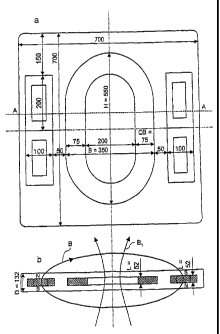
Figures la and lb show a first embodiment of the invention,
in which the illustrated dimensions shall be regarded as
being only by way of example. The apparatus 1 according to
the invention comprises a mat 10 which is subdivided into
three sections and can be folded, of which only the central
section 12 is illustrated, extending in the plane of the
drawing. A second device, at right angles to the plane of the
drawing and in the form of a flat toroidal coil 14, is
embedded in the section 12 of the mat 10 in order to produce
a second magnetic field in cushioning 16 composed of a
flexible material, for a example a foam material. The
toroidal coil or transmission coil 14 extends in the plane of
the drawing with a width of about B = 350 mm and a height of
about H = 550 mm, with the head ends 14a, 14b each being
designed to be semicircular. The length of the coil at right
angles to the plane of the drawing is about L = 52 mm. The
cross section through the coils is defined by the length L
and a cross-sectional width of about QB = 75 mm. The
thickness of the mat is about D = 132 mm, with the toroidal
CA 02448573 2003-11-25
16
coil being arranged centrally in the mat, so that cushioning
16, which is also about 40 mm, is in each case arranged
between the mat upper face and lower face. There are two
devices 22, 24, 26, 28 in each case to the left and to the
right of the coil in order to produce a first magnetic field,
and these each comprise a fixed magnet 32, 34, 36, 38 and an
auxiliary coil 42, 44, 46, 48 in each case, which surround
the fixed magnets in the mat plane. Each device 22, 24, 26,
28 has a height of about 200 mm, a width of about 100 mm and
a length L at right angles to the plane of the drawing of
about 52 mm. The devices 22, 24, 26, 28 are each separated by
about 50 mm from the toroidal coil 14 in the direction of the
width, and two of the devices 22 and 24 as well as 26 and 28
are in each case adjacent to one another in the vertical
direction.
90 nuclear magnetic resonance signal pulsed method
= As has already been stated above, a first embodiment of the
invention uses a pulsed method, which will be described in
detail in the following text.
The molecules or macromolecule complexes of our body are made
up predominantly of hydrogen atoms, for example in water
(H20) or in organic molecules (for example in CH2 or CH3). The
= 25 cores or ions of the hydrogen are protons. Protons have a
magnetic moment and a spin (obviously a torque) with a ratio
y (gyromagnetic factor) between them. For protons,
y = 2.67522 108T-1s-1. A steady-state magnetic field Bo, for
example the earth's magnetic field, produces macroscopic
magnetization M(t) exponentially over time with a time
constant Tl. This is defined by:
M(t)
CA 02448573 2003-11-25
17
where
MO %BO
where Tl is the spin lattice relaxation time and Mo is the
asymptotic value of the magnetization. The time profile of
the magnetization M(t) which is produced by a sudden
application of a magnetic field Bo which is constant after
the rise is illustrated in Figure 2. For protons or hydrogen
in human tissue:
Tl = lOs ... 10-3 s.
A spin echo measurement is preferably carried out before the
therapeutic treatment, in order to determine the spin lattice
relaxation time.
The macroscopic magnetization M is aligned asymptotically
parallel to applied magnetic field B = Bo, as is illustrated
in Figure 3. Figure 3 also shows a rectangular and right-
handed coordinate system XYZ, which is used as the basis of
the orientation for the following analysis.
Microscopically and as required by quantum mechanics, all of
the proton spins carry out a precession movement about Bo at
a frequency fo. This frequency is referred to as the Larmor
frequency. The Larmor frequency fo is determined as follows:
00
fr, =
" 27c
From this, in the earth's magnetic field, that is to say for
Bo= 0.5 Gauss = 5-10-5T
CA 02448573 2003-11-25
18
f Bo 2 67522 = lOt = 5 40-5 .2128,872 Hz
2n
In the earth's magnetic field, the Larmor frequency for
protons is in consequence about 2 kHz. The Larmor frequency
is also varied only very slightly by the chemical bonds.
Figure 5 shows an oscilloscope print-out for experimental
verification of the Larmor frequency by means of a spin echo
measurement with 500 ml of water at 100 kHz and using a
23.5 gauss spectrometer. A 900 pulse and a 180 pulse are
injected, and the spin echo is detected. Figures 6 to 8 show
the spin echoes for a first magnetic field B = 23.2 gauss,
23.4 gauss and 23.8 gauss on an enlarged time scale. The
first magnetic field B is produced by parallel
superimposition of a constant magnetic field Bo, by means of
the four fixed magnets which are in the form of ferrite
magnets 32, 34, 36, 38, and of a magnetic field ABo, which
varies with time, produced by the four auxiliary coils 42,
44, 46, 48.
Figure 9 illustrates the three measurement points from
Figures 6 to 8 in the form of a graph of the magnetic field
in gauss as a function of the relative frequency in Hz. The
straight line is a linear interpolation through the
measurement points. The relative frequency represents the
frequency error from the resonant frequency fo, which is
defined by the basic field Bo = 23.5 gauss.
The apparatus according to the invention comprises a flat
coil or transmission coil 14 for producing the second
magnetic field in the form of a magnetic alternating field Bl
at a frequency fo of about 100 kHz. This frequency
CA 02448573 2003-11-25
19
corresponds approximately to the Larmor frequency of protons
in a mean magnetic field of B = 23.5 gauss.
For this purpose, the transmission coil 14 is preferably
connected in a very simple manner to a capacitor in order to
form a resonant circuit. The resonant frequency of the
resonant circuit fLc is
1
LC= 274
where L is the inductance of the transmission coil 14, and C
is the capacitance of the capacitor.
If the body areas of a patient or of biological tissue are
located in the first magnetic field B, which initially has a
constant strength of Bo = 23.5 gauss, the macroscopic
magnetization M of the tissue is the vector sum of the
nuclear spins parallel to Bo, when Bo in this embodiment runs
parallel to the Z-axis (see Figure 3).
A nuclear magnetic resonance method is now used to deflect
the magnetization M away from the Bo direction. Nuclear
magnetic resonance changes the magnetization direction, even
though the body is at rest. The induced voltage produces an
effect as if the body were in motion. Nuclear magnetic
resonance can then be used to carry out therapy by
stimulating the metabolism.
A so-called 90 radio-frequency pulse is used to rotate the
magnetization through 90 . The time profile of the magnetic
field and of the magnetization components Mx(t) and M(t) is
shown schematically in Figure 4. The transmission coil, whose
axis runs parallel to the X axis, generates a rotating radio-
CA 02448573 2003-11-25
frequency field B1, or one which oscillates linearly in the X
direction. The macroscopic magnetization M rotates at a
frequency fl about the X axis from the positive Z direction
to the X-Y plane. In this case:
5
f/ M1/211
where
at. = Yea
10 The angle a through which M rotates is:
a ¨
For a 90 rotation, that is to say a = n/2, the time duration
15 of the 90 pulse t90 is calculated to be:
n 1
" 2 713
The macroscopic magnetization M is in the direction Y after
20 injection of the 90 pulse. It rotates at coo about the Z axis
and induces a voltage in the radio-frequency coil, which can
be measured as a nuclear magnetic resonance signal. This
signal decays exponentially with the time constant T2*, and:
Mx5, Mo = e-t/T2'
For a homogeneous magnetic field B: T2* T2
where T2 is the spin-spin relaxation time.
For a less homogeneous magnetic field B: T2* < T2
For liquids: Tl -1= T2
CA 02448573 2003-11-25
21
Typical values for T2 are:
Tap water: T2 3 s
Distilled water: T2 -14 30 s to 3 min
Human tissue: T2 10 MS to 1 S
Tissue of a hand: T2 -7.4 100 MS to 1 s.
Fast adiabatic nuclear magnetic resonance run
With reference to Figures 10a to 10c and, alternatively, the
pulsed method described above, specific rotation of the
magnetization is achieved by means of a fast adiabatic run,
which is described in the following text. This is achieved by
a field variation of the first magnetic field B or a
frequency variation of the alternating field B1, in which
case the magnetization M can be rotated from 0 to 180 with
respect to the Z axis.
The following magnetic fields are defined in a coordinate
system (X' Y' Z) which rotates at wo about the Z axis:
AB0 = B - Bo where Bo = w/y
B1 and
BR =
In this case, Bl is an alternating field or radio-frequency
field which is produced by the transmission coil 14 and, at
the time t = to, runs parallel to the X' axis in the
coordinate system X'Y'Z. BR is the magnetic field or
treatment field which results from the superimposition of B
and B1.
Figure 10a shows the alignment of the magnetic field vectors
in space at an instant relating to the time to. The
illustration shows the vector of the fourth magnetic field
CA 02448573 2003-11-25
22
AB , produced by the auxiliary coils 42, 44, 46, 48, and
which runs parallel to the Z axis. In this case, AB is the
positive or negative excess of the magnetic field B above or
below the resonant third magnetic field Bo, respectively,
which is produced by the ferrite magnets 32, 44, 46, 48,
points in the positive Z direction all the time, and is not
illustrated in Figures 10a to 10c.
If only the magnetic field B(t) = Bo acts initially, then the
macroscopic magnetization of the tissue is aligned in the
direction of the Z axis and the individual spins precess at
the angular frequency coo about the Z axis. This means that
the spins are initially stationary with respect to the
rotating coordinate system X'Y'Z.
The third magnetic field AB and the alternating field Bi,
which are superimposed to form the resultant magnetic field
BR, are now increased until the time t = to. The vector of
the alternating field Bi(to) points in the direction of the
X' axis.
The alternating field B1 oscillates linearly at the frequency
(Do essentially at right angles to the Z axis. Alternatively,
the field Bl may also rotate at the frequency coo about the Z
axis. This is equivalent in terms of the projection in the
X'-Z plane. Since the nucleus spins also rotate about the Z
axis at the same frequency coo, they are always in phase with
the alternating field Bi.
Based on a classical interpretation, a resultant force F
always acts on the magnetization or the spins in this
arrangement, with this force F rotating the magnetization M
or the spins in the X'-Z plane away from the Z axis. During
this rotation, the spins essentially precess in phase. This
CA 02448573 2003-11-25
23
rotation reduces the fourth magnetic field or modulation
field AB0 to zero and then increases it further again
continuously in the negative Z direction, in order to follow
the change in the magnetization direction. This makes it
possible to rotate the magnetization into the direction of
the negative Z axis, that is to say to rotate the
magnetization of the nuclei through 1800
.
Figure 10b shows the alignment of the magnetization M and of
the various magnetic fields at a time tl, which occurs later
than to. The magnetization vector M has already been rotated
to a considerable extent away from the Z axis.
In a corresponding manner, Figure 10c shows an instant
relating to a time t2 which occurs even later than tl.
In order to maximize the desired effect of motion simulation,
the magnetization M should be rotated as frequently as
possible. For this purpose, the auxiliary coil which produces
the magnetic field AB() is moved in a triangular shape, in a
sawtooth shape or in a sinusoidal shape between AB?" and
-AB?", that is to say symmetrically around zero. At the top,
Figure 11 shows schematically the most preferred triangular-
waveform modulation of the first magnetic field B(t). The
times to, ti and t2 from Figures 10a to 10c are also shown.
When the magnetic field B(t) is falling, the transmission
coil and the alternating field B1 are switched on in order to
rotate the magnetization away from the positive Z axis, while
the transmission coil is switched off when the field rises.
In consequence, the alternating field B1(t) is amplitude-
modulated with a square-waveform according to this exemplary
embodiment. Other modulation forms for the first and/or
second magnetic field, for example sinusoidal amplitude
modulation, are, however, likewise within the scope of the
CA 02448573 2003-11-25
24
invention. The blocks 50 which are shown at =the bottom of
Figure 11 represent, schematically, the on-time of the
alternating field Bi. During the off-time of the alternating
field Bi, the spins relax, and the magnetization decreases
again. The modulation period of the first and the fourth
magnetic field is thus matched to the spin lattice relaxation
time of the tissue, or at least corresponds to its order of
magnitude. The period of the variation of the first magnetic
field with time is preferably from one tenth to 10 times, in
particular from once to 3 times or 5 times, the spin lattice
relaxation time.
It is also within the scope of the invention for the falling
flank of the modulation field AB to be made to be steeper
than the rising flank, in order to achieve faster rotation.
The adiabatic run has been explained above by means of
modulation of the first magnetic field B(t). The run can also
be carried out analogously with a constant first magnetic
field B = Bo and a corresponding frequency change (so-called
frequency sweep) of the alternating field Bl.
In addition, a receiving coil whose axis is in the Y
direction detects the induced nuclear magnetic resonance
signal, and is sensitive to its phase. The time integral of
this signal is proportional to the total nuclear magnetic
resonance effect, and is thus maximized.
One advantage of the adiabatic run is that the first magnetic
field B may have up to about 10% inhomogeneity. This means
that the method is several orders of magnitude less sensitive
in this context than known methods, such as the spin echo
method. The invention is also correspondingly insensitive to
the angle between the first and second magnetic fields.
CA 02448573 2003-11-25
Figure 12 shows an example of a circuit arrangement for the
apparatus according to the invention, it respectively having
an amplifier 52 and 54 for driving the transmission coil 14
and the auxiliary coils 42, 44, 46, 48. A control device or
5 control logic 56 is associated with the transmission coil 14
and with the auxiliary coils 42, 44, 46, 48, as well as with
the two amplifiers 52 and 54, and controls the modulation of
the first and second magnetic fields.
10 Figures 13a and 13b show a second embodiment of the
invention. In this case, Figure 13a shows a view of this
second embodiment and Figure 13b shows a section drawing
along the section line A-A in Figure 13a. The mat 10 has a
flat toroidal coil 15 in whose inner area 151 two further
15 flat toroidal coils 17 and 19 are arranged. In the same way
as the embodiment which has been described with reference to
Figures la and lb, this embodiment is also suitable, for
example, for implementing the 900 nuclear magnetic resonance
signal pulsed method and the fast adiabatic nuclear magnetic
20 resonance run.
The toroidal coil 15 produces a quasi-static magnetic field
B(t) = Bo + AB0(t). In order to achieve a wide treatment
range, the magnitude of ABo(t) is preferably half as much as
25 Bo.
The flat toroidal coils 17 and 19 are operated in opposite
senses, so that a north pole and a south pole respectively of
the two coils point toward one face of the mat 10. In this
way, these coils produce a magnetic field B1 which, in the
areas 21 and 23 above and below the mat 10, is essentially at
right angles to the magnetic field B which is produced by the
toroidal coil 15. When a patient is lying on the mat, then
the tissue of the patient is located within this area 21. The
CA 02448573 2003-11-25
26
area 21 thus defines a treatment area for the tissue to be
treated.
The time profile of the magnetic field B(t) and of the
magnetic field Bl is in this case controlled as has been
described above with reference to the further embodiments.
In contrast to the first embodiment of the invention, the
magnetic field B in the treatment area runs approximately at
right angles to the mat surface, however, or at right angles
to the magnetic field B(t) produced by the coils 22, 24, 26,
and 28 in the first embodiment. Furthermore, no fixed magnets
are required for the second embodiment. The constant magnetic
field component Bo can in fact be produced by suitable
operation of the toroidal coil 15, in the same way as the
magnetic field ABo which varies with time.
Figure 14 shows, in the form of a block diagram, suitable
=control for the coils 15, 17 and 19 for producing a quasi-
static magnetic field B(t), as well as an alternating field
B1(t) with a time profile as illustrated, by way of example,
in Figure 11. In a similar way to the control illustrated in
Figure 12, the control has a logic circuit 56. The logic
circuit 56 drives an amplifier 58 for driving the toroidal
coil 15, as well as an amplifier for driving the toroidal
coils 17 and 19 in order to produce the alternating field 131.
The amplifier 58 in this case produces a constant current for
an embodiment without permanent magnets, which produces a
constant magnetic field Bo in the coil 15, as well as a
current which is applied thereto, varies with time, and
produces the variable magnetic field component ABo.
In summary, the present invention proposes a magnetic field
therapy apparatus and a magnetic field therapy method which
CA 02448573 2003-11-25
27
use the nuclear magnetic resonance signal as a motion sensor
in order to stimulate the metabolism. The signal in this case
simulates the motion of a body part. One advantageous feature
in this case is that the proposed nuclear magnetic resonance
therapy in all probability has no negative effects on the
organism.
The nuclear magnetic resonance therapy apparatus according to
the invention allows the magnetization to be rotated quickly
and using little energy. The rotation is carried out, in
particular, within one microsecond up to 30 seconds.