Note: Descriptions are shown in the official language in which they were submitted.
CA 02448747 2003-11-27
WO 02/096598 PCT/US02/16216
AN APPARATUS AND METHOD FOR MACHINING WITH
CRYOGENICALLY COOLED OXIDE-CONTAINING
CERAMIC CUTTING TOOLS
BACKGROUND OF THE INVENTION
The present invention relates to the field of machining of materials by
cutting (e.g.,
shaping parts by removing excess material in the form of chips), and more
particularly
machining of materials by cutting with cryogenically cooled oxide-containing
ceramic cutting
tools.
to As used herein, the term "cutting" includes but is not limited to the
following operations:
turning, boring, parting, grooving, facing, planing, milling, drilling and
other operations which
generate continuous chips or fragmented or segmented chips. The term cutting
does not
include: grinding, electro-discharge machining, ultrasonic cutting, or high-
pressure jet erosion
cutting, i.e., operations generating very fine chips that are not well defined
in shape, e.g., dust
or powder.
The term "oxide-containing ceramic cutting tool," as used herein, includes
cutting tools
(or cutting tips or cutting bits) made of oxide-containing ceramic materials
and/or any other
advanced tool materials containing at least 5% by weight of an oxide ceramic
phase.
2o The "material removal rate," a measure of machining productivity, is the
volume of
material removed by a tool per unit time and is defined by the machining
parameters selected
for the operation. In the case of turning, the most generic cutting operation,
the material
removal rate is the product of cutting speed, tool feed-rate, and depth of
cut. The objective is
to enable machining at a higher cutting speed, a higher feed-rate, a greater
depth of cut, or at
any combination of these parameters leading to an overall increase in material
removal rate.
Alternatively, the objective is to enhance the life of cutting tools in order
to minimize the down-
time spent for tool change-over and/or to reduce worn tooling costs. In
certain machining
operations, it is sometimes desired to increase cutting speed only while
keeping material
removal rate constant, or even reducing it, in orderto produce an improved
surface finish of a
3o machined part or to reduce cutting force and/or part fixturing
requirements. This can be
accomplished by a corresponding reduction in feed-rate or depth of cut, or
both. The
undesired effect of such a manipulation with machining parameters is a
significant increase in
tool temperature leading to its premature wear and failure. The objective is
to minimize this
undesired effect.
3s Driven by economic factors, the machining industry is interested in
achieving cost-
reductions by:
increasing material removal rates without increases in worn toot and tool
change-
over costs, thereby increasing productivity;
CA 02448747 2003-11-27
WO 02/096598 PCT/US02/16216
2
increasing cutting speeds without increases in worn tool and tool change-over
costs; ,
turning or milling hard parts which, in the past, could have been produced
only via
expensive grinding operations; and
using cleaner, safer, and more health-acceptable machining methods to
eliminate
numerous costs associated with conventional cutting fluids (e.g., emulsions)
and
clean-up operations.
New, advanced cutting tool materials recently have been developed and
commercialized to address these needs and improve the cutting performance of
to conventional tools made of high-speed steel (HSS) or tungsten carbide-
cobalt (WC/Co).
Compared to tools made of HSS and WC/Co, these new tools are significantly
harder but
also are much more brittle and sensitive to load stress and/or thermal stress
shocking.
Some of these advanced cutting materials, such as oxide ceramics and cermets,
are
capable of operating at relatively high temperatures. (Cermets are dense
composite
materials comprising both ceramic and metallic phases. As applied in the field
of machining
technologies, the term cermet includes carbide, nitride, boride, oxide and/or
other more
complex ceramic particles bonded or infiltrated with alloyed metals, but
excludes the
conventional WC/Co "hard metals.") However, the wear behavior of oxide
ceramics is less
predictable than that of HSS, WC/Co or other advanced tool materials. After an
initial,
2o usually negligible, cratering, flank wear, and/or notching, the oxide
ceramic tools usually
fracture catastrophically within the cutting edge area or nose, resulting in
machining down-
time and, frequently, in a damaged work-piece surface.
Table 1 below compiles typical values of thermo-mechanical properties of some
of
the most popular cutting tool materials. Compared to carbide, nitride, and
diamond-based
cutting tools, the oxide ceramic-based tools show significantly lower values
of a combined
traverse rupture strength, fracture toughness, and thermal conductivity, while
revealing a
dangerously high thermal expansion coefficient. This makes the oxide ceramic
tools prone
to brittle fracture under mechanical load as well as cracking due to a
localized thermal
expansion in thermal gradient.
CA 02448747 2003-11-27
WO 02/096598 PCT/US02/16216
3
TABLE 1: Thermo-mechanical Properties of Popular Cutting Tool Materials
Tool material Traverse Fracture Thermal Thermal
rupture toughness expansion conductivity
strength (K~c) coefficientat
(M Pa) M Pa m (ppm/C) 20C (W /
-~~2 m C)
AI203 550 4 8 9
AI203-Ti C 800 4.5 8 16-21
AIzOs-1 %ZrOz ~ 700 5.5 8.5 10
SiAION 800 6.5 3 2--20
Si3N4 100-800 1.5-5.5 3.5 7-54
SiC 550-860 4.6 4.5 57-77
Polycryst. CBN 800-1100 4.5 5 100
(PCBN)
Polycryst. Diamond390-1550 6-8 4 560
(PCD)
WCICo (TiC-TaC 2000-3400 9 4-6 80-121
addit.)
Data compiled from: "Ceramics and Glasses, Engineered Materials Handbook",
Vol.4, ASM
Int., The Materials Information Soc., 1991, "Microstructural Effects in
Precision Hard
Turning", Y.K. Chou and C.J, Evans, MED-Vol. 4, Mfg. Sci. and Engr., ASME
1996., and
"Temperature and UI/ear of Cutting Tools in Higf~-speed Macf~ining of Inconel
798 and Ti-
6AI-6V-2Sn", T. Kitagawa et al., Wear 202 (1997), Elsevier, pp. 142-148.
It is recognized that all conventional coolants and cutting fluids, including
room-
temperature water and an emulsified oil, as well as evaporative-cooling fogs
or oil mists, can
1o thermally shock and fracture oxide ceramics. The machining community is
well aware of the
need to avoid the use of these cutting fluids and coolants when machining with
oxide
ceramic cutting tools. Numerous publications, research papers, and tool
manufacturers'
recommendations warn machining operators about a drastic reduction of ceramic
tool life on
contact with conventional cutting fluids or even with a small residue of such
fluids on
workpiece surfaces. Despite numerous inherent deficiencies, e.g., overheated
workpiece,
reduced dimensional accuracy, and risk of chip fires, dry machining is
recommended when
ceramic cutting tools are used.
P.K. Mehrotra of Kennametal teaches in the "Applications of Ceramic Cutting
Tools",
Key Engineering Materials, Vol. 138-140 (1998), Chapter 1, pp. 1-24 that: "the
use of
2o coolants is not recommended when these [ceramic] tools are used to machine
steels due to
their low thermal shock resistance". R. Edwards states: "this ceramic [AI203-
Zr02 white
ceramic] has a low thermal conductivity which makes it susceptible to thermal
shock and so
the use of coolant should be avoided", "Cutting Tools", The Institute of
Materials, 1993, p.
20. According to D'errico, et al, "when a coolant is used, alumina,
alumina/zirconia, and
CA 02448747 2003-11-27
WO 02/096598 PCT/US02/16216
4
alumina/TiC tools, with one exception, tend to have poor performance probably
due to
limited thermal shock capability resulting from high thermal expansion
coefficients",
"Performance of Ceramic Cutting Tools in Turning Operations'; Industrial
Ceramics, Vol 17,
#2, 1997. A 1995 ASM handbook adds: "water or oil coolants are not recommended
for use
with cold-pressed AI2O3-base ceramics because they may cause the insert to
crack. If
carbide tooling is used to machine a part run with coolant and a subsequent
operation is
planned using a cold-pressed oxide-base ceramic, the residual coolant should
be blown
away from the part", ASM Specialty Handbook, "Tool Materials", 1995, p. 73.
R.C. Uewes
and D.K. Aspinwall ("The Use of High Speed Machining for the Manufacture of
Hardened
1o Steel Dies", Trans. ofNAMRIlSME, Vol. XXIV,1996, pp.21-26) tested a range
of oxide and
nitride tools including: 71 %AI203-TiC (mixed alumina), 75%AIz03-SiC (whisker
reinforced
alumina), 50%CBN-AIB2-AIN, 50%-TiC-WC-AIN-AIB~, 80%CBN-TiC-WC, as well as
95%CBN-Ni/Co. They found that the use of conventional cooling fluid applied by
flooding or
spraying resulted in the reduction of tool life by more than 95% except for
the whisker
reinforced alumina for which the life was shortened by about 88%.
The oxide ceramics have one thing in common with all of the other cutting tool
materials - - as their temperature increases, they soften, weaken, and build-
up localized,
internal stresses (due to thermal expansion frequently compounded with a
limited
conductivity) which ultimately leads to a limit in the cutting speed, material
removal rate,
2o and/or the hardness ofworkpieces machined. This common characteristic of
tool materials
is well described by E.M. Trent and P.K. Wright in "Metal Cutting", 4th Ed.,
Butterworth,
Boston, Oxford, 2000, and in the ASM Handbook on "Machining, Ceramic
Materials".
Thus, a problem facing the machining industry is the inability to use
conventional
cooling methods with oxide ceramic cutting tools, i.e., the thermo-mechanical
limitation on
2s further increases in cutting speed, material removal rate, and/or the
hardness of workpieces
being machined.
Other problems facing the machining industry include significant environmental
and
health related problems associated with the conventional cutting fluids and
coolants
presently used in the industry. For example, carbon dioxide (COQ), a commonly
used
3o coolant, is a greenhouse generator. Also, since COz is denser than air it
presents a
potential asphyxiation concern. In addition, COZ also has the potential to
cause acid
corrosion, since it is soluble in water. Freons and freon substitutes, some
other corr~monly
used coolants, also are greenhouse generators and ozone depleters. These
substances
CA 02448747 2003-11-27
WO 02/096598 PCT/US02/16216
also are explosive and/or toxic when heated on contact with red-hot solids.
Other
coolants which can be explosive include hydrocarbon gases and liquefied
ammonia.
Coolants such as cryogenic/liquefied air with oxygen in it can result in chip
fires.
There exists a relatively large body of prior art patents pertaining to
cryogenic cooling
5 of cutting tools, including: U.S. Pat. Nos.: 5,761,974 (Wang, et al.),
5,901,623 (Hong),
3,971,114 (Dudley), 5,103,701 (Lundin, et al.), 5,509,335 (Emerson), 4,829,859
(Yankoff),
5,592,863 (Joskowiak, et al.) and WO 99/60079 (Hong). However, neither these
patents nor
the other prior art references discussed herein solve the problems discussed
above or
satisfy the needs set forth below.
to It is desired to have an apparatus and a method that enables machining
operators to
increase machining speeds and/or material removal rates without shortening the
useful life
of tools made of oxide-containing ceramic materials and/or any other advanced
tool
materials containing a significant fraction of oxide ceramic phase.
It is further desired to have an improved apparatus and a method for cooling
and
is strengthening cutting tools made of materials revealing a tendency to wear
and fail by brittle
cracking so as to enable cutting at increased speed without reducing the
useful life of cutting
tools.
It is still further desired to have an apparatus and a method that increase
material
cutting speeds and/or productivity, which are limited by the lifetime (and
cost) of cutting
20 tools.
It is still further desired to have an apparatus and a method for machining
materials
and/or parts that cannot tolerate elevated temperatures generated on contact
with the hot
edges) of cutting tools.
It is still further desired to have an apparatus and a method for machining a
25 workpiece which improves safety and environmental conditions at work places
by minimizing
the risks of chip fires, burns and/or chip vapor emissions while using an
environmentally
acceptable, safe, non-toxic and clean method of cooling cutting tools.
It also is desired to have an apparatus and a method for machining a workpiece
which overcome the difFiculties and disadvantages of the prior artto provide
better and more
3o advantageous results.
BRIEF SUMMARY OF THE INVENTION
Applicants discovered that if oxide-containing ceramic cutting tools, both
brittle and
CA 02448747 2003-11-27
WO 02/096598 PCT/US02/16216
6
thermal shock-sensitive, are cooled during machining with a cryogenic fluid,
the life of
the cutting tools increases and cutting at higher speeds and/or with higher
material removal
rates becomes feasible and cost-effective. This result was surprising and
unexpected to
Applicants and would be surprising and unexpected to others skilled in the
art. Nothing in
the prior art has indicated such a desired outcome for oxide-containing
ceramic cutting tools.
In fact, as indicated above, the prior art has taught away from Applicants'
invention.
Applicants' invention is an apparatus and a method for machining a workpiece.
Another aspect of the invention is a workpiece machined by the apparatus and
the method.
An additional aspect of the invention is an oxide-containing ceramic cutting
tool adapted to
1o be cryogenically cooled in the apparatus for machining a workpiece adjacent
the oxide-
containing ceramic cutting tool.
A first embodiment of the apparatus for machining a workpiece includes: an
oxide-
containing ceramic cutting tool adjacent the workpiece; and a means for
cryogenically
cooling the oxide-containing ceramic cutting tool.
There are many variations of the first embodiment of the apparatus. In one
variation,
the oxide-containing cutting tool contains at least about 5% by weight of an
oxide ceramic
phase. In another variation, at least a portion of the cutting tool is frosted
when the
workpiece contacts the cutting tool.
In a preferred embodiment of the apparatus; the means for cryogenically
cooling the
oxide-containing ceramic cutting tool includes a cryogenic fluid. Preferably,
the cryogenic
fluid is selected from a group consisting of liquid nitrogen, gaseous
nitrogen, liquid argon,
gaseous argon and mixtures thereof.
There are several variations of the preferred embodiment of the apparatus. In
one
variation, at least a portion of the cryogenic fluid is a two-phase fluid. In
another variation,
the cutting tool has a cutting edge and the means for cryogenically cooling
the cutting tool
includes a means for delivering a portion of the cryogenic fluid to the
cutting tool, said
means for delivering having at least one discharge point spaced apart from
.the cutting edge
by a distance greater than or equal to about 0.150 inches and less than about
3.0 inches.
In a most preferred embodiment of the apparatus, at least a portion of the
cryogenic
3o fluid is delivered to the oxide-containing ceramic cutting tool in the form
of a cryogenic jet. In
one variation of this embodiment, the cutting tool has a rake surface and at
least a portion of
the cryogenic jet impinges on at least a portion of the rake surface. In
another variation, at
least a portion of the cryogenic jet has a temperature below about minus 150
degrees
CA 02448747 2003-11-27
WO 02/096598 PCT/US02/16216
Celsius (-150°C).
7
Another embodiment of the apparatus for machining a workpiece includes: an
oxide-
based ceramic cutting tool adjacent the workpiece; a supply of a cryogenic
fluid; and a
means for delivering a portion of the supply of the cryogenic fluid to the
oxide-based ceramic
cutting tool in the form of a cryogenic jet discharged from a location spaced
apart from the
cutting tool.
Another aspect of the invention is a workpiece machined by an apparatus as in
any
of the aforesaid embodiments and characterized by an improved surtace.
A first embodiment of the method for machining a workpiece includes multiple
steps.
l0 The first step is to provide an oxide-containing ceramic cutting tool
adjacent the workpiece.
The second step is to cryogenically cool the oxide-containing ceramic cutting
tool.
There are several variations of the first embodiment of the method. In one
variation,
at least a portion of the cutting tool is frosted when the workpiece contacts
the cutting tool.
In another variation, the oxide-containing cutting tool contains at least
about 5% by weight of
an oxide ceramic phase.
In a preferred embodiment of the method, the oxide-containing ceramic cutting
tool is
cryogenically cooled by a cryogenic fluid. Preferably, the cryogenic fluid is
selected from a
group consisting of liquid nitrogen, gaseous nitrogen, liquid argon, gaseous
argon and
mixtures thereof.
2o There are several variations of the preferred embodiment of the method. In
one
variation, at least a portion of the cryogenic fluid delivered to the cutting
tool is a two-phase
fluid. In another variation, the cutting tool has a cutting edge, and a means
for delivering a
portion of the cryogenic fluid to the cutting toot has at least one discharge
point spaced apart
from the cutting edge by a distance greater than or equal to about 0.150
inches and less
than about 3.0 inches.
In a most preferred embodiment of the method, at least a portion of the
cryogenic
fluid is delivered to the oxide-containing ceramic cutting tool in the form of
a cryogenic jet. In
one variation of this embodiment, at least a portion of the cryogenic jet has
a temperature
below about minus 150 degrees Celsius (-150°C).
3o Another embodiment of the method for machining a workpiece includes
multiple
steps. The first step is to provide an oxide-based ceramic cutting tool
adjacent the
workpiece. The second step is to provide a supply of a cryogenic fluid. The
third step is to
deliver a portion of the supply of the cryogenic fluid to the oxide-based
ceramic cutting tool
CA 02448747 2003-11-27
WO 02/096598 PCT/US02/16216
8
in the form of a cryogenic jet discharged from a location spaced apart from
the cutting tool.
Another aspect of the invention is a workpiece machined by a method as in any
of
the aforesaid embodiments and characterized by an improved surface.
BRIEF DESCRIPTION OF THE DRAWINGS
The invention will be described by way of example with reference to the
accompanying drawings, in which:
Figure 1 is a schematic illustration of one embodiment of the invention; and
Figures 2A and 2B are schematic illustrations of alternate embodiments of the
to invention.
DETAILED DESCRIPTION OF THE INVENTION
The present invention is an apparatus and a method which use cryogenic cooling
and/or freezing of the rake surface and the rest of a cutting tool made of
oxide-containing
ceramic materials, known for their tendency to fail during machining
operations by brittle
fracture. In a preferred embodiment, a cryogenic fluid is applied directly to
the surface of an
oxide-containing ceramic cutting tool, but other ways of cryogenic cooling of
the oxide-
containing ceramic cutting tool are within the scope of this invention. In a
most preferred
embodiment, a jet of cryogenic fluid having a temperature of about minus 150
degrees
2o Celsius (-150°C) or (ess is discharged directly at the rake surface
of the cutting tool.
Additionally, Applicants have developed the following guidelines to match the
amount of
cryogenic cooling with actual machining conditions for cutting operations
carried out in a
normal, ambient air environment:
(1 ) cryogenic fluid cooling operations should be carried out with some white
frost
coating on the cutting tool or cutting insert surface to obtain the full
benefits
of the present invention;
(2) if a frost line forms near the cutting edge which moves back toward the
other
end of the cutting tool during cutting operations, the cooling effect is
diminished, indicating the need for an increase in flowrate and/or pressure of
3o the cryogenic fluid;
(3) if the chip or work surface just below the cutting edge is bright red, or
appears to melt, or burn, the flowrate and/or pressure of the cryogenic fluid
must be increased;
CA 02448747 2003-11-27
WO 02/096598 PCT/US02/16216
9
(4) if the tool nose or the perimeter of the chip contact area on the rake
surface is cherry-red, there is no need to increase the flowrate and/or
pressure of the cryogenic fluid unless the frosted coating on the tool starts
to
shrink;
(5) if the tool nose or the perimeter of the chip contact area on the rake
surface
is intensely bright red, the flowrate and/or pressure of the cryogenic fluid
must be increased regardless of the condition of the frosted coating on the
tool surface; and
(6) an exception to guidelines (1) -(5) would apply if machining is carried
out
1o under very low humidity conditions in a controlled atmosphere chamber or in
a vacuum where the benefits of the invention could be achieved without
producing a white frost coating.
The apparatus and the method for cooling cutting tools will improve
environmental
conditions and safety at workplaces by using clean coolants and reducing the
risk of chip
fires, operators' burns and/or toxic chip vapor emissions, and will reduce
environmental
problems by using coolants with no greenhouse and ozone-depletion potential.
In addition to direct jetting of a cryogenic fluid, other methods of applying
cryogenic
fluid to oxide-containing ceramic tools are within the scope of this
invention, as are other
methods of cryogenically cooling such cutting tools without the use of
cryogenic fluids. These
2o methods include but are not limited to: (1 ) closed-cycle cryogenic mini-
refrigerators deriving
their cooling power from the Joule-Thompson expansion of a high-pressure gas,
(2)
magnetocaloric effect refrigerators suggested first by W.F. Giauque and P.
Debye in 1926,
(3) cascaded thermoelectric cells, and (4) laser beam refrigeration of certain
solids. Since
these and similar methods necessitate an indirect cooling of cutting tools via
a thermally
conductive toolholder or additional chill-plates, such methods are more
complex and
expensive than the preferred methods of the present invention, especially in
the case of
heavier cutting operations and/or larger cutting tools.
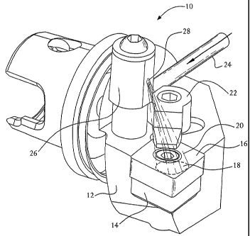
Figure 1 illustrates a preferred embodiment of the invention in which a jet of
cryogenic fluid is directed at the surface of an oxide-containing ceramic
cutting tool. The
3o apparatus 10 includes a conventional toolholder 12 used in turning
operations and a
conventional carbide shim 14 supporting a cutting insert 16. The impingement
spot 18 of
direct impingement of the cryogenic fluid 20 on the surface of the cutting
insert is illustrated
schematically in Figure 1. The impinged fluid spreads out of the impingement
spot in radial
CA 02448747 2003-11-27
WO 02/096598 PCT/US02/16216
directions. The cutting insert 16 is made of an oxide-containing ceramic
material. Other
components of the apparatus include an insert holding clamp 22 used in certain
types of
tooling (a non-essential component) and a thin tubing 24 for delivering the
cryogenic fluid to
a cryogenic fluid nozzle assembly 26 for directing the jet toward the cutting
insert through an
5 orifice 28 in the nozzle assembly. The nozzle assembly shown in Figure 1 is
an adjustable
geometry, add-on component of the tooling. Other fixed geometry nozzles also
can be used
to practice the invention.
Figures 2A and 2B are schematic illustrations of two alternate embodiments of
an
apparatus 50 taught by the present invention. Referring to Figure 2A, a clamp
16 is attached
to to a toolholder 54 by a bolt 58 or another fastening mechanism. An oxide-
containing
ceramic cutting insert 52 is supported by a carbide shim plate or other
material. Cryogenic
fluid passes through a delivery tube 60 and through a bore 62 which is drilled
throughout the
clamp to form a nozzle. A jet of cryogenic fluid 64 expands from the nozzle
onto the cutting
insert. In the most preferred mode of operation, the expanding jet terminates
at the surface
1s of the cutting insert. Alternatively, the jet may be allowed to expand
further away to reach
the chip 72 evolving from the workpiece 70 as well as the surface of the
workpiece around
the chip and the tool/workpiece contact zone. The workpiece moves across the
cutting
insert at a relative cutting speed V~. The embodiments shown in Figures 2A and
2B differ in
the configuration of the bore 62 drilled throughout the clamp to form a nozzle
and in the
location of the discharge point, as discussed below.
The embodiments shown in Figures 2A and 2B minimize the extent of
modifications
needed on a standard machining tool set-up to practice the present invention.
The cryogenic
fluid jetting nozzle is incorporated into a metal clamp 56 commonly used for
holding the
cutting inserts 52 in work position, which cutting inserfis in this case are
made of oxide-
2s containing ceramics. The clamp may be bored to discharge the fluid as shown
in Figure 2A
with the discharge point nearthe surtace of the cutting insert. Alternatively,
the bore 62 may
project cryogenic fluid from a discharge point located above the surface of
the cutting insert
as shown in Figure 2B. In both configurations, both the exit of the nozzle and
the front part
of the clamp are located away from the chip 72 evolving from the workpiece 70
during
3o cutting, and are never in continuous contact with the chip and do not
participate in the chip
breaking operation.
To be fully effective, the cryogenic fluid 20 must be sufficiently cold (i.e.,
below about
-150°C or-238°F) at the discharge point, which is the
termination of the jetting nozzle in the
CA 02448747 2003-11-27
WO 02/096598 PCT/US02/16216
11
preferred embodiment as shown in Figure 1. The cryogenic fluid preferably is
selected
from the following: liquid nitrogen, a 2-phase mixture of liquid nitrogen and
its vapor or a
warmer nitrogen gas, a cryogenic vapor of liquid nitrogen, a warmer nitrogen
gas chilled to
below about -150°C, liquid argon, a 2-phase mixture of liquid argon and
its vapor or a
warmer argon gas, a cryogenic vapor of liquid argon, a warmer argon gas
chilled to below
about -150°C, or any combination of the above. However, persons skilled
in the art will
recognize that other cryogenic mixtures of liquids, gases, and solid particles
could be used
as the cryogenic fluid.
Preferably, the cryogenic fluid jet is turned on at least 10 to 20 seconds
before the
oxide-containing ceramic cutting too! begins cutting, i.e., contacting the
workpiece and
making chips. This "cooldown" is sufficient to pre-quench the most typical
oxide-containing
ceramic tools or inserts to cryogenic temperatures required to practice the
invention.
However, turning the cryogenic fluid on when the tool touches the workpiece or
even a few
seconds later also is acceptable. It is observed that the effect of the
cryogenic fluid cooling
is inversely proportional to the cumulative time during which the cutting tool
is exposed to
high temperature, i.e., the more complete is the cryo-cooling cycle, the more
significant
improvements in tool life are expected over a dry cutting condition. The
cryogenic fluid flow
can be turned off at the same moment at which the tool completes a cutting
contact, i.e.,
making chips.
2o To be effective, the cryogenic fluid 20 jetted directly at the rake surface
must impinge
on the entire rake surface area or on at least 20% of the total rake surface
area located on
the side of the cutting edge. (Rake surface is the cutting tool surface
adjacent the cutting
edge which directs the flow of the chip away from the workpiece. In the
embodiment shown
in Figure 1, rake surface is the top surface of the cutting insert 16. The
rake surface may be
completely flat, chamfered, or may have a more complex, three-dimensional
topography
produced by molding or an addition of a plate in order to provide an enhanced
control chip
flow and/or chip breaking.) Regardless of its topography, 20% of the rake
surface area is the
minimum impingement surface area assuring that the entire cutting tool, or
cutting insert 16
made of oxide-containing ceramic material, becomes cryogenically cold and
relatively
3o uniform in temperature. With this approach to cryogenic impingement
cooling, a tiny hot spot
within the cutting tool material underthe chip contact zone becomes smaller
and engulfed by
the cryogenically cold material. As a result, the entire cutting tool, or the
cutting insert,
becomes harder and stronger, and its thermal expansion-induced, internal
stresses are
CA 02448747 2003-11-27
WO 02/096598 PCT/US02/16216
12
reduced. The fact that the cutting insert becomes more resistant to fractures
during
cutting is an unexpected discovery or finding that could not be anticipated
from the prior art.
In a preferred embodiment, the cryogenic fluid 20 is discharged directly at
the rake
surface of the cutting tool using an "external" nozzle located behind, above,
or at the rake
surface, but never closely to the cutting edge in a direct and continuous
contact with or
adjacent to the chip evolving from this edge. The straight-line distance
between the nozzle
opening (discharge point) and the cutting edge is at least about 0.150 inches
(3.8 mm) but
not more than about 3.0 inches (76 mm). This range of discharge or jetting
distances is
important for proper operation because: (1) if the discharge distance was
shorter, the
1o cryogenic fluid jet expanding from the external nozzle would not be able to
directly impinge
on at least 20% of the total rake surface area on the side of the cutting
edge; and (2) if the
discharge distance was longer, the warm ambient air, entrained into the
expanding cryogenic
jet from the surroundings would raise the overall jet temperature to well
above
-150°C, thereby rendering the entire impingement cooling effect less
effective.
15 The external nozzle can be made of tubing terminating behind, above, or at
the rake
surface. Alternatively, it can be made in the form of a channel drilled in the
insert holding
clamp 22 holding the cutting tool on the back end within the toolholder 12. It
can be formed
by any provision made and attached to the insert holding clamp orthe
toolholderwhich has a
channel drilled for the discharge of the cryogenic fluid 20 from the desired
distance at the
2o rake surface and toward the cutting edge. The nozzle exit can be round or
flat vertically or
horizontally, converging, straight or diverging. There are no particular
limitations on fihe
nozzle in the present invention, as long as the nozzle jets the cryogenic
fluid at the rake
surface from the desired distance in the desired direction white away from the
chip. A multi-
nozzle system may be beneficial in certain cutting operations, especially if
the depth of cut
25 and feed-rate are very low, e.g., 0.020 inches (0.51 mm) and 0.004
inches/revolution
(0.1 mm/revolution) respectively. When the tool nose and/or cutting edge are
so marginally
"immersed" in the workpiece material, it is sometimes helpful to provide
cooling to the flank
and/or clearance walls in addition to the rake surface.
The present invention is based on a possibly complete cryogenic cooling or
freezing
30 of the rake surface and the rest of a cutting tool made of oxide-containing
ceramic materials
known for their tendency to fail during cutting operations by brittle
fracture. To accomplish
this, enough cryogenic fluid must be jetted at the cutting tool to keep the
cutting tool walls
frosted during the entire cutting operation in spite of the fact that a
significant amount of
CA 02448747 2003-11-27
WO 02/096598 PCT/US02/16216
13
cutting heat enters the cutting tool through the hot chip contact area. If the
frost line
forms during cutting near the cutting edge and contact zone on the side walls
and the rake
surface which moves back toward the other end of the cutting tool, the
cryogenic cooling
effect is diminished, indicating the need for an increase in flowrate and/or
pressure of the
cryogenic fluid. Any tool cryo-cooling operation carried out without some
white frost coating
on the cutting tool or cutting insert surface would not obtain the full
benefits achieved with
the present invention. An exception would be if machining is carried out
under' very low
humidity conditions, in a controlled atmosphere chamber or in a vacuum where
the benefits
could be achieved without producing a white frost coating. Under preferred
conditions, no
to frost coating is expected to develop inside the direct impingement spot 18
of the cryogenic
fluid 20, preferably a moisture-free product of nitrogen or argon. Thus, a
part of the rake
surface and/or sidewall surface may be free of frost because of continuous
washing by a
rapidly expanding and moisture-free cryogenic fluid.
Another important diagnostic method for carrying out cutting according to the
present
invention is to observe the dynamic effects at the cutting tool/workpiece
interface -- chip, tool
nose, and workpiece surface just below the cutting edge. First, if the chip or
work surface
just below the cutting edge is bright red, or appears to melt, or burn, the
flowrate and/or
pressure of the cryogenic fluid 20 must be increased. Second, if the tool nose
or the
perimeter of the chip contact area on the rake surface is cherry-red, there is
no need to
2o increase the flowrate and/or pressure of the cryogenic fluid unless the
frosted coating on the
tool starts to shrink. Third, if the tool nose or the perimeter of the chip
contact area on the
rake surface is intensely bright red, the flowrate and/or pressure of the
cryogenic fluid must
be increased regardless of the condition of the frosted coating on tool
surface. An
occasional increase in the heat generation at the workpiece/cutting tool
contact area may
indicate geometric or compositional inhomogeneities of the work material, and
could easily
be quenched by increasing the flowrate of the cryogenic fluid to the point at
which the whole
contact zone, not just the tool surtace is cooled in a direct impingement
mode. A cutting tool
cryo-cooling operation carried out according to the above guidelines will
provide for improved
results. Of course, other, more elaborate methods of diagnostics may include,
but are not
limited to, use of thermocouples, infra-red sensors, temperature sensitive
coatings, etc.
It was surprising and unexpected to Applicants that their cryogenic fluid
cooling
method resulted in an apparent strengthening and an enhanced machining
performance of
oxide-containing ceramic cutting tools, which normally tend to wear and fail
by brittle
CA 02448747 2003-11-27
WO 02/096598 PCT/US02/16216
14
cracking under dry machining conditions and catastrophically fracture on
contact with
conventional, room-temperature cutting fluids, or residues thereof. As shown
in the
examples below, the present invention results in productivity improvements of
about 98% to
about 182% and tool life improvement of about 250%. These improved results
were
surprising and unexpected to Applicants and would be surprising and unexpected
to other
persons skilled in the art.
While the exact reasons for the surprising and unexpected results which
provide a
substantial improvement over the prior art are not clear, it appears that
these results may be
due to a combination of factors. Without wishing to be bound by any particular
theory,
1o Applicants believe that these factors include but are not limited to: (1 )
cryogenic hardening
of the entire cutting tool material,.(2) reduction in thermal expansion-driven
stresses within
the entire cutting tool, and most unexpectedly, (3) reduction in thermal
gradients at cutting
tool surfaces due to a boundary film effect and/or the Leidenfrost phenomenon.
The
boundary film is a jetting condition-controlled, semi-stagnant, transient film
which "softens"
the cryogenic chilling effect and "smoothens" thermal profiles at the
impingement-cooled
surface. The Leidenfrost phenomenon occurs to a larger or smaller degree with
all liquids
sprayed at a target surface that is hotter than the boiling point of the
liquid. Liquid droplets
boil above the hot surface, or the hot surface is screened by a layer of
vapor. In the case of
cryogenic liquids, especially if colder than minus 150°C, all cutting
tool surfaces are hot,
2o which means that a typical cryo-liquid jet slides on a boundary film of its
vapor without
directly wetting the tool. This makes the thermal profile of the cryojet-
cooled cutting tool
surface smoother. In the case of an oil or water-based cutting fluid, with its
boiling point
significantly higher than room temperature, bailing occurs only at a very
close distance from
the perimeter of chip contact zone at the cutting tool surface. When the chip
changes
direction during cutting, or the tool encounters a sudden cutting
interruption, such a
conventional fluid spreads over a suddenly exposed, hottest tool surface area
where it boils
explosively releasing vapor, microdroplets, and pressure waves. Applicants
believe that the
preferred method of their invention promotes formation of a thin boundary film
and/or a
Leidenfrost effect, which prevents) fracturing of oxide-containing ceramic
cutting tools that
3o catastrophically fracture on contact with conventional, room-temperature
cutting fluids.
EXAMPLES
The following nomenclature is used in the examples below:
f: feed rate in units of inches per revolution or ipr (mm/rev)
CA 02448747 2003-11-27
WO 02/096598 PCT/US02/16216
doc: depth of cut in units of inches (mm)
U: cutting speed in units of feet per minute or SFM (m/min)
MRR: material removal rate in units of cubic inches per minute (cm3/min)
5 Example 1: Roughing of hardened, forged steel, 64 Rockwell hardness on scale
C (64 HRc)
In this operation, a 0.5" (12.7 mm) round ceramic tool insert (Ah03-TiC/black
ceramic) was used for roughing a hardened, forged steel part and results were
compared
between dry and cryo-cooled processes. The machining parameters are as
follows:
fDRY = 0.005 ipr (0.13 mm/rev) fcRVO = 0.007 ipr (0.18 mm/rev) doc = 0.150
in.(3.8 mm)
1o UoRy = 348 SFM (106 m/min) UCRYO = 700 SFM (213 m/min)
Using cryo-cooling of the cutting tool, a significant increase in cutting
speed was
achieved, which in turn, contributed to increased material removal rate. The
MRR for dry
cutting was 3.1 in3/min (50.8 cm3/min), whereas forthe cryo-cooled cutting,
the MRR was 8.8
in3/min. (144.2 cm3/min), thereby resulting in a productivity improvement of
about 182%.
15 Many attempts were subsequently made to increase the cutting speed, feed
rate, and MRR
in the dry cutting operation in order to approach the performance level of the
cryogenic fluid.
All of these attempts resulted in rapid fractures and catastrophic failures of
the ceramic
insert.
It also was observed that, in spite of the increased cutting speed, teed rate,
and
2o MRR, the surface of the forged steel part machined with cryogenic fluid was
exceptionally
clean, unoxidized, and shiny, providing a significant improvement over the
surface condition
resulting from the conventional cutting method. It was further observed that
the dimensional
accuracy, e.g., tapering, of the forged steel part machined according to this
cryogenic fluid
method was improved.
Example 2: Finishing of hardened, forged steel (64 HRC)
In this operation, a 0.5" (12.7 mm)round ceramic tool was used for finish
turning the
same part (example 1 ) and results were compared between dry and cryo-cooled
processes.
The machining parameters are as follows:
3o fpRy = 0.006 ipr (0.15 mm/rev) fcRYO = 0.010 ipr (0.25 mm/rev)
doc = 0.070 in. (1.78 mm) UpRy = 434 SFM (132 m/min)
UCRYO = 693 SFM (211 m/min)
Using cryo-cooling of the cutting tool, a significant increase in cutting
speed was
CA 02448747 2003-11-27
WO 02/096598 PCT/US02/16216
16
achieved, which in Turn, contributed to increased material removal rate. The
MRR
for dry cutting was 2.2 in3/min. (36 cm3/min), whereas for the cryo-cooled
cutting, the MRR
was 5.8 in3/min. (95 cm3/min), thereby resulting in-a productivity improvement
of about
166%.
Attempts were subsequently made to increase the cutting speed, feed rate, and
MRR
in the dry cutting operation in order to approach the performance level of the
cryogenic fluid.
All of these attempts resulted in rapid fractures and catastrophic failures of
the ceramic
insert.
It also was observed that, in spite of the increased cutting speed, feed rate,
and
1o MRR, the surface of the forged steel part machined with cryogenic fluid was
exceptionally
clean, unoxidized, and shiny, providing a significant improvement over the
surface condition
resulting from the conventional cutting method. It was further observed that
the dimensional
accuracy of the forged steel part machined according to this cryogenic fluid
was improved.
Example 3: Roughing of cast steel (48 - 52 HRC)
In this operation, a LNU 6688 (iS0) ceramic tool insert was used for rough
turning
the main body of a cast steel part and results were compared between dry and
cryo-cooled
processes. The machining parameters for both dry and cryo-cooled processes are
as
follows:
2o f = 0.011 ipr (0.28 mm) doc = 0.330 in. (8.38 mm) U = 424 SFM (129 m/min)
The tool life for dry cutting was 20 min., whereas the tool life for cryo-
cooled cutting
was 70 min., thereby resulting in a tool life improvement of 250%. It was also
observed that
the surface of the cast steel part machined with cryogenic fluid was
exceptionally clean,
unoxidized, and shiny, providing a significant improvement over the surface
condition
resulting from the conventional cutting method. It was further observed that
the dimensional
accuracy, e.g., tapering of the cast steel part machined according to this
cryogenic fluid
method was improved.
Example 4: Finishing of forged steel (48 - 52 HRC)
3o In this operation, a 1" (25.4 mm) round ceramic tool insert (AIZO3-
TiC/black ceramic)
was used for rough turning the main body of a forged steel part and results
were compared
between dry and cryo-cooled processes. The machining parameters are as
follows:
f = 0.020 ipr (0.51 mm/rev) doc = 0.017 in. (0.43 mm)
CA 02448747 2003-11-27
WO 02/096598 PCT/US02/16216
17
UpRy = 259 SFM (79 m/min) U~~= 583 SFM (178 m/min)
Using cryo-cooling of the cutting tool, a significant increase in cutting
speed was
achieved, which in turn, contributed to increased material removal rate. The
MRR for dry
cutting was 1.1 in3/min. (18 cm3/min), whereas for the cryo-cooled cutting,
the MRR was 2.4
in3/min. (39 cm3/min), thereby resulting in a productivity improvement of
about 118%.
Many attempts were subsequently made to increase the cutting speed of MRR in
the
dry cutting operation in order to approach the performance level of the
cryogenic fluid. All of
these attempts resulted in rapid fractures and catastrophic failures of the
ceramic insert.
It was observed that, in spite of the increased cutting speed and MRR, the
surface of
to the forged steel part machined with cryogenic fluid was exceptionally
clean, unoxidized, and
shiny, providing a significant improvement over the surface condition
resulting from the
conventional cutting method. It was further observed that the dimensional
accuracy of the
forged steel part machined according to this cryogenic fluid method was
improved.
Example 5: Roughing of 83CrMo135 steel
In this operation, a LNU 6688 ceramic tool insert (Ah03-ZrO~/white ceramic)
was
used for roughing a 83CrMo135 steel part and results were compared between dry
and cryo-
cooled processes. The machining parameters are as follows:
f= 0.0157 ipr (0.4 mm/rev) doc = 0.060 in. (1.52 mm)
UpRy= 512 SFM (156 m/min) UCRYO= 1020 SFM (311 m/min)
Using cryo-cooling of the cutting tool, a significant increase in cutting
speed was
achieved, which in turn, contributed to increased material removal rate. The
MRR for dry
cutting was 5.8 in3/min. (95 cm3/min), whereas forthe cryo-cooled cutting, the
MRRwas 11.5
in3/min. (188 cm3/min), thereby resulting in a productivity improvement of
about 98%.
2s Attempts were subsequently undertaken to increase the cutting speed and MRR
in
the dry cutting operation in order to approach the performance level of the
cryogenic fluid.
All of these attempts resulted in rapid fractures and catastrophic failures of
the ceramic
insert.
It also was observed that, in spite of the increased cutting speed and MRR,
the
3o surface of the 83CrMi135 steel part machined with cryogenic fluid was
exceptionally clean,
unoxidized, and shiny, providing a significant improvement over the surface
condition
resulting from the conventional cutting method. The dimensional accuracy ofthe
83CrMi135
steel part machined according to this cryogenic fluid method was improved.
CA 02448747 2003-11-27
WO 02/096598 PCT/US02/16216
18
Example 6: Turning and Facing of a 9310 carburized steel bearing plate (60
HRC)
In this operation, two different oxide-containing ceramic tool inserts were
used for
turning and facing of a bearing plate and results were compared between dry
and cryo
cooled processes. Varying feeds, speeds and depths of cut were used to finish
the part.
Using cryo-cooling of the cutting tool, a significant increase in cutting
speed was achieved,
which in turn, contributed to reduced cycle time for the part. The normal
cycle time of 75
min. using dry cutting was reduced to 28 min. using cryo-cooled cutting,
thereby resulting in
a productivity improvement of about 168%.
l0 Many attempts were subsequently made to shorten the cycle time using the
conventional processes in order to approach the performance level of the
cryogenic fluid. All
of these attempts resulted in rapid fractures and catastrophic failures of the
ceramic insert.
It also was observed that, in spite of a much faster cutting, the surface of
the 9310
carburized steel bearing plate machined with cryogenic fluid was exceptionally
clean,
unoxidized, and shiny, providing a significant improvement over the surface
condition
resulting from the conventional cutting method. It was further observed that
the dimensional
accuracy of the plate machined according to this cryogenic fluid method was
improved.
Although illustrated and described herein with reference to certain specific
embodiments, the present invention is nevertheless not intended to be limited
to the details
2o shown. Rather, various modifications may be made in the details within the
scope and range
of equivalents of the claims and without departing from the spirit of the
invention.