Language selection

Search

Patent 2448850 Summary

Third-party information liability

Some of the information on this Web page has been provided by external sources. The Government of Canada is not responsible for the accuracy, reliability or currency of the information supplied by external sources. Users wishing to rely upon this information should consult directly with the source of the information. Content provided by external sources is not subject to official languages, privacy and accessibility requirements.

Claims and Abstract availability

Any discrepancies in the text and image of the Claims and Abstract are due to differing posting times. Text of the Claims and Abstract are posted:

  • At the time the application is open to public inspection;
  • At the time of issue of the patent (grant).
(12) Patent: (11) CA 2448850
(54) English Title: DEVICE FOR TURNING STRIPS
(54) French Title: DISPOSITIF POUR RETOURNER DES BANDES
Status: Deemed expired
Bibliographic Data
(51) International Patent Classification (IPC):
  • B65H 23/32 (2006.01)
(72) Inventors :
  • RICHERT, WITHOLD (Germany)
  • BUENTEN, ROLF (Germany)
(73) Owners :
  • SMS SIEMAG AKTIENGESELLSCHAFT (Germany)
(71) Applicants :
  • SMS DEMAG AKTIENGESELLSCHAFT (Germany)
(74) Agent: RICHES, MCKENZIE & HERBERT LLP
(74) Associate agent:
(45) Issued: 2010-01-26
(86) PCT Filing Date: 2002-05-31
(87) Open to Public Inspection: 2002-12-19
Examination requested: 2007-05-01
Availability of licence: N/A
(25) Language of filing: English

Patent Cooperation Treaty (PCT): Yes
(86) PCT Filing Number: PCT/EP2002/006007
(87) International Publication Number: WO2002/100749
(85) National Entry: 2003-11-20

(30) Application Priority Data:
Application No. Country/Territory Date
101 28 576.0 Germany 2001-06-13

Abstracts

English Abstract


The invention relates to a method for turning and reorienting the displacement
direction of strips (1), especially of a thin hot strip. The strip can be
turned about any angle by means of at least one deflection roller, with roller
banks (5) which are arranged on the circumference of the deflection roller,
and which respectively comprise a plurality of individual rollers. Plastic and
elastic deformations are avoided due to the fact that the strip is supported
at various points by the individual rollers of successive roller banks (5).
The invention also relates to a device for carrying out the method. Said
device enables the roller banks placed one after the other in the strip
deflection direction to be staggered in relation to each other in such a way
that the contact surfaces of their rollers with the strip are staggered from
bank to bank, by one roller width (11,12).


French Abstract

L'invention concerne un procédé pour retourner des bandes (1) et modifier leur sens d'avance, ce procédé s'appliquant en particulier à une bande mince à chaud. Selon ce procédé, la bande peut être retournée selon un angle voulu par l'intermédiaire d'au moins un rouleau de retournement au moyen de bancs de rouleaux (5) disposés à la périphérie du rouleau de retournement, ces bancs comprenant chacun plusieurs rouleaux individuels (11, 12). Selon l'invention, pour éviter les déformations plastiques et élastiques, la bande est soutenue en différents points par les rouleaux individuels de bancs de rouleaux (5) successifs. L'invention concerne également un dispositif permettant de mettre en oeuvre ce procédé. Dans ce dispositif, les bancs de rouleaux placés les uns derrière les autres dans le sens de retournement de la bande sont décalés les uns par rapport aux autres de telle sorte que les surfaces de contact de leurs rouleaux avec la bande soient décalées d'une largeur de rouleau (11, 12) de banc à banc.

Claims

Note: Claims are shown in the official language in which they were submitted.


What is claimed is:


1. Device for turning and reorienting the running
direction of thin hot metal strip, comprising at least one
deflection roller (2) and roller banks (5) which are
arranged on the circumference of the deflection roller, the
roller banks (5) having individual rollers wherein the
strip (1) can be turned about any angle by the at least one
deflection roller (2) by means of the roller banks (5), and
in which the strip is supported at different points by the
individual rollers of successive roller banks (5), such
that the roller banks (5) successively arranged in the
strip turning direction are staggered relative to each
other in such a way that the contact surfaces of the
individual rollers (4 or Ri to R6) with the strip (1) are
staggered from roller bank to roller bank by a width of one
roller of the immediately preceding roller bank, wherein
the width (7) of the individual rollers (4 or R1 to R6) is
different from roller bank (5) to roller bank.


2. Device in accordance with claim 1, wherein the
diameters of the individual rollers (4 or R1 to R6) of a
roller bank (5) are different.


7

Description

Note: Descriptions are shown in the official language in which they were submitted.


CA 02448850 2003-12-15

DEVICE FOR TURNING STRIPS

The invention concerns a device for turning and reorienting
the running direction of strips, especially thin hot strip, in
which the strip can be turned about any angle by at least one
deflection roller by means of roller banks, which are arranged on

the circumference of the deflection roller, such that the strip
is supported at different points by the individual rollers of
successive roller banks, and such that the roller banks
successively arranged in the strip turning direction are
staggered relative to each other in such a way that the contact
surfaces of their rollers with the strip are staggered from
roller bank by one roller width.

A strip deflection device for turning metal strips is
already known, in which a rotatable drum is oriented with its
axis inclined to the running direction of the strip that is
running in, and the strip follows a helical path, which advances
at an angle of twist relative to the circumferential arc, along
an arc of contact.

Several guide pieces are arranged on the surface of the drum
side by side in the circumferential direction and in such a way
that they can be moved in the axial direction of the drum, so

1


CA 02448850 2003-12-15
1 . ,

that the strip can be deflected by the desired angle according to
the angle of twist and the arc of contact (DE 25 40 714).

A further development is described in DE 38 27 864 C2. In
this design, the individual rollers are supported in roller
strips and are detachably mounted on the surface of the
deflecting cylinder in such a way that they are parallel and
staggered relative to one another and form a helical deflecting
surface.

The disadvantage of these previously known devices for
turning and reorienting strips is that their arrangements of the
rollers or roller banks cause plastic and elastic deformations in
the strips with decreasing strip thicknesses.

The strip to be turned has contact with the rollers of all
of the roller banks in the same place. This causes off-flatness,
especially when small strip thicknesses are involved.

Another disadvantage is that the rollers leave an impression
in the strip with decreasing strip thickness. The distance
between two adjacent rollers on a roller bank in accordance with
the previous designs is permanently predetermined by the bearing
width and the angle of inclination of the rollers to the axis of
the drum. Therefore, it is not possible to alter the distance
between the individual rollers.

2


CA 02448850 2009-01-16

supported by an air cylinder and a supporting device is
arranged on the bottom side of the other end. When the air
cylinder is actuated, the body is moved from the horizontal
position into an inclined position.
Starting from the above-mentioned prior art, the
objective of the invention is to specify a device that
prevents plastic and elastic deformations, which occur
especially during the turning and reorienting of thin
strips.
In a device for turning and reorienting the running
direction of strips, especially thin hot strip, in which
strip can be turned about any angle by at least one
deflection roller by means of roller banks, which are
arranged on the circumference of the deflection roller, and
in which the strip is supported at different points by the
individual rollers of successive roller banks, such that
the roller banks successively arranged in the strip turning
direction are staggered relative to each other in such a
way that the contact surfaces of their rollers with the
strip are staggered from roller bank to roller bank by one
roller width, the solution of this objective resides in
that the width of the individual rollers is different from
roller bank to roller bank.
Since the strip is supported over its entire length in
the course of the strip deflection by the rollers of each
successive roller bank, which are staggered relative to the
rollers of the preceding roller bank, there is significant
reduction of deformation and considerable improvement of
flatness. The strip can no longer be pulled between two
adjacent rollers of a roller bank, which is a disadvantage
of the previous designs that causes problems especially in
the region near the edge of the strip.

3


CA 02448850 2009-01-16

It is advantageous in this connection that the
diameters of the individual rollers of a roller bank are
different, and that advantageously the width of the
individual rollers is different.
In one aspect, the present invention resides in a
device for turning and reorienting the running direction of
thin hot metal strip, comprising at least one deflection
roller and roller banks which are arranged on the
circumference of the deflection roller, the roller banks
having individual rollers wherein the strip can be turned
about any angle by the at least one deflection roller by
means of the roller banks, and in which the strip is
supported at different points by the individual rollers of
successive roller banks, such that the roller banks
successively arranged in the strip turning direction are
staggered relative to each other in such a way that the
contact surfaces of the individual rollers with the strip
are staggered from roller bank to roller bank by a width of
one roller of the immediately preceding roller bank,
wherein the width of the individual rollers is different
from roller bank to roller bank.
The invention is explained in greater detail below on
the basis of a specific embodiment.

3a


CA 02448850 2003-11-20

Figure 1 shows a deflection roller as a single unit with a
strip running in and running out.

Figure 2 shows the deflection roller of Figure 1 as viewed
towards an end face.

Figure 3 shows a top view of a roller bank as a single unit
of the deflection roller of Figure 2.

Figure 4 shows a perspective view of the deflection roller
of Figure 1 with an additionally installed steering roller stand.
Figure 5 shows the polygonization of the strip around the

individual rollers of the successive roller banks in a
perspective view.

Figure 6 shows an arrangement with two successive roller
banks of the deflection roller of Figure 2.

Figure 7 shows a view as in Figure 6, but with wider rollers
than in Figure 6.

As shown in Figure 1, a strip 1 is run in at an angle of 45'
to the longitudinal axis 3 of the deflection roller 2 and run
back out, also at an angle of 45', to achieve a deflection of
90'.

In this design, the strip 1 winds around the deflection
roller 2 over half of its circumference.

The rollers 4 are arranged in banks 5 and are distributed
over the region of the deflection roller 2 that the strip 1 winds
around.

4


CA 02448850 2003-11-20

Figure 2 shows an arrangement of seven roller banks 5, which
are arranged with uniform angular separation along half the
circumference of the deflection roller 2.

For a deflection of 90', the individual rollers 4 on a
roller bank 5 are aligned at 45'.

In accordance with Figure 3, the strip 1 is supported by six
rollers 4(Ri to R6). These six rollers 4(R1 to R6) have the
same diameter 6 and the same width 7.

The distance 8 between the center width of the first roller
Ri and the center width of the sixth roller R6 is the same as the
width 9 of the strip. The right and left edges of the strip 1
thus lie on the center axis 10 of the rollers R1 and R6 and are
supported.

In Figure 4, a steering roller stand 11 is additionally
installed. It establishes a uniform tension on the strip 1. The
drawing also shows how the edge of the strip 1 is supported by
the roller 4, only half of which is concealed by the strip 1.

Figure 5 shows the strip 1 as it is being uniformly
supported by the individual rollers 4 of the roller banks 5.
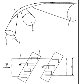
Figure 6 shows an arrangement with two roller banks 5 of the

deflection roller of Figure 2. In the running direction 13 of
the strip 1, the contact of the strip with the rollers 4 of
roller bank 5 is staggered by the width of a roller 4 from the


CA 02448850 2003-11-20

first roller bank 5 to the next roller bank 5.

However, it is also possible, as shown in Figure 7, to
design the individual rollers of a roller bank 5 with a width 11
that is different from the width 12 of the individual rollers 4
of the adjacent roller bank 5.

Staggered contact between the strip and the rollers can also
be achieved by the installation of rollers with slightly varied
diameters.

The impressions and off-flatness that occur with the
previously known devices, especially in the case of thin hot
strip, are avoided by the measures described above.

6

Representative Drawing
A single figure which represents the drawing illustrating the invention.
Administrative Status

For a clearer understanding of the status of the application/patent presented on this page, the site Disclaimer , as well as the definitions for Patent , Administrative Status , Maintenance Fee  and Payment History  should be consulted.

Administrative Status

Title Date
Forecasted Issue Date 2010-01-26
(86) PCT Filing Date 2002-05-31
(87) PCT Publication Date 2002-12-19
(85) National Entry 2003-11-20
Examination Requested 2007-05-01
(45) Issued 2010-01-26
Deemed Expired 2011-05-31

Abandonment History

There is no abandonment history.

Payment History

Fee Type Anniversary Year Due Date Amount Paid Paid Date
Registration of a document - section 124 $100.00 2003-11-20
Application Fee $300.00 2003-11-20
Maintenance Fee - Application - New Act 2 2004-05-31 $100.00 2003-11-20
Maintenance Fee - Application - New Act 3 2005-05-31 $100.00 2005-04-29
Maintenance Fee - Application - New Act 4 2006-05-31 $100.00 2006-04-26
Request for Examination $800.00 2007-05-01
Maintenance Fee - Application - New Act 5 2007-05-31 $200.00 2007-05-10
Maintenance Fee - Application - New Act 6 2008-06-02 $200.00 2008-05-22
Maintenance Fee - Application - New Act 7 2009-06-01 $200.00 2009-04-29
Registration of a document - section 124 $100.00 2009-09-09
Final Fee $300.00 2009-09-14
Owners on Record

Note: Records showing the ownership history in alphabetical order.

Current Owners on Record
SMS SIEMAG AKTIENGESELLSCHAFT
Past Owners on Record
BUENTEN, ROLF
RICHERT, WITHOLD
SMS DEMAG AKTIENGESELLSCHAFT
Past Owners that do not appear in the "Owners on Record" listing will appear in other documentation within the application.
Documents

To view selected files, please enter reCAPTCHA code :


To view images, click a link in the Document Description column. To download the documents, select one or more checkboxes in the first column and then click the "Download Selected in PDF format (Zip Archive)" or the "Download Selected as Single PDF" button.

List of published and non-published patent-specific documents on the CPD .

If you have any difficulty accessing content, you can call the Client Service Centre at 1-866-997-1936 or send them an e-mail at CIPO Client Service Centre.


Document
Description 
Date
(yyyy-mm-dd) 
Number of pages   Size of Image (KB) 
Representative Drawing 2010-01-04 1 7
Cover Page 2010-01-04 2 44
Claims 2003-11-20 2 34
Abstract 2003-11-20 2 85
Drawings 2003-11-20 3 45
Description 2003-11-20 6 206
Representative Drawing 2003-11-20 1 10
Cover Page 2004-01-29 2 43
Description 2003-12-15 6 200
Description 2009-01-16 7 235
Claims 2009-01-16 1 28
PCT 2003-11-20 13 527
PCT 2003-12-15 4 163
Assignment 2003-11-20 4 133
Correspondence 2004-01-26 1 26
Assignment 2004-02-04 3 95
Prosecution-Amendment 2007-05-01 1 42
PCT 2003-11-21 3 147
Fees 2007-05-10 1 43
Prosecution-Amendment 2008-12-10 2 53
Assignment 2009-10-06 18 872
Prosecution-Amendment 2007-07-26 2 45
Prosecution-Amendment 2009-01-16 7 205
Assignment 2009-09-14 1 59
Correspondence 2009-09-14 1 59
Correspondence 2009-10-05 1 20
Assignment 2009-09-09 17 779
Assignment 2009-10-06 18 865