Note: Descriptions are shown in the official language in which they were submitted.
CA 02448951 2011-05-30
TEMPORARY ALARM LOCATE WITH INTERMITTENT WARNING
BACKGROUND OF THE INVENTION
The present invention generally relates to an alarm system including
multiple adverse condition detectors for detecting an adverse condition in a
building. More specifically, the present invention is directed to a method and
system for providing an improved method of determining which of the adverse
condition detectors is sensing the adverse condition during the generation of
an
alarm signal by all of the adverse condition detectors.
Alarm systems which detect dangerous conditions in a home or
business, such as the presence of smoke, carbon dioxide or other hazardous
elements, are extensively used to prevent death or injury. In recent years, it
has
been the practice to interconnect different alarm units that are located in
different
rooms of a home. Specifically, smoke detecting systems for warning inhabitants
of
a fire include multiple detectors installed in the individual rooms of a home,
and
the detectors are interconnected so that the alarms of all the detectors will
sound if
only one detector senses any combustion products produced by a fire. In this
way,
individuals located away from the source of the combustion products are
alerted as
to the danger of fire, as well as those in closer proximity to the fire.
Although the generation of an audible alarm signal by each of the
adverse condition detectors is an effective way to alert the building
occupants that
an adverse condition is occurring near one of the detectors, a desire exists
to allow
the occupants to rapidly determine which of the interconnected detectors is
the
detector actually sensing the adverse condition. This detector is often
referenced to
as the local detector.
One known method of indicating which of the adverse condition
detectors is sensing the adverse condition is to activate a visual indicator
on only
the adverse condition detector that is sensing the adverse condition. Although
this
1
CA 02448951 2003-11-12
type of visual indication does allow the occupant to determine which of the
detectors is generating the alarm condition, it requires the occupant to
visually
examine each of the alarms during the generation of the alarm signal. Thus,
the
occupant must allow the alarm signal to continue to operate while a visual
inspection of each of the adverse condition detectors is undertaken.
Another system currently exists that disables the interconnect line
extending between the multiple adverse condition detectors upon activation of
a
switch placed in the interconnected system. When the switch is activated, only
the
adverse condition detector sensing the adverse condition will continue to
generate
the alarm signal. The remaining remote alarm units are thus silenced for the
entire
duration of a predetermined silence period. In this manner, the occupants can
simply depress a button or switch located somewhere within the building to
disable
the generation of the alarm signal by all of the adverse condition detectors
except
the adverse condition detector sensing the adverse condition and generating
the
local alarm signal. This system allows the occupant to more quickly determine
which of the adverse condition detectors is sensing the adverse condition by
listening for which of the detectors continues to generate the alarm signal
after the
switch has been activated.
In the prior art system identified above, the interconnect disabling
circuit includes a timed feature such that the generation of the alarm signal
by the
remote interconnected adverse condition detectors is disabled for only a
predetermined period of time, this period being preset at approximately ten
minutes
and subsequently enabled with each actuation of the appropriate button.
However,
during the entire duration of this disable period, the only alarm generating
the
alarm signal is the alarm sensing the adverse condition being sensed.
Although the alarm disable feature identified above is able to allow
the occupant to more easily determine which of the adverse condition detectors
is
originating the alarm signal, disabling the generation of the alarm signal by
the
interconnected adverse condition detectors for an extended period of time may
allow the occupants to fall into a momentary state of complacency. For
instance, if
2
CA 02448951 2003-11-12
the originating detector is in a distant corner or floor of a home, it may be
either
inaudible or diminished to a point that it does not call the occupant to
immediate
action. Since the point of having alarms sounding together is to provide the
earliest warning of an adverse condition throughout the home, the disabling of
the
alarm signal by all of the interconnected adverse condition detectors for the
entire
disable period is not desirable.
SUMMARY OF THE INVENTION
The present invention provides a method of determining which
adverse condition detector of a plurality of interconnected adverse condition
detectors is sensing an adverse condition during the generation of an alarm
signal
by all of the adverse condition detectors. When one of the adverse condition
detectors senses the presence of an adverse condition, the adverse condition
detector generates a local alarm signal and an interconnect signal. Upon
receiving
the interconnect signal, the remaining interconnected remote adverse condition
detectors simultaneously generate an alarm signal. Thus, when any one of the
adverse condition detectors is sensing an adverse condition, all of the
adverse
condition detectors are sent into an alarm condition as is conventional.
The method of the present invention allows an occupant to actuate a
test switch on any of the remote detectors to initiate an alarm locate period.
During
the alarm locate period, the local detector sensing the adverse condition
continues
to generate the alarm signal while the generation of the alarm signal by all
of the
remote detectors is intermittently disabled and enabled. Thus, during the
alarm
locate period, the only adverse condition detector continuously generating an
alarm
signal is the adverse condition detector actually sensing the adverse
condition.
During the alarm locate period, which has a fixed duration, the
interconnect signal alternates between a period of being enabled and disabled
for a
number of repeating alarm interrupt cycles. In a conventional smoke alarm
system
using a legacy DC level to indicate an interconnect status, this signal
alternates
between a high level and a low level for a number of repeating alarm interrupt
cycles. During each alarm interrupt cycle, the interconnect signal has a high
level
3
CA 02448951 2003-11-12
for an enable period and a low level for a disable period. Each of the remote
adverse condition detectors generates the alarm signal only during the enable
period of each alarm interrupt cycle.
Preferably, the disable period of the alarm interrupt cycle is selected
to be substantially longer than the enable period such that the remote
detectors
generate the alarm signal for only a small portion of the alarm interrupt
cycle. The
enable period allows the alarm signal to be generated by the remote adverse
condition detectors such that an occupant is periodically reminded that an
adverse
condition has been detected by one of the adverse condition detectors of the
alarm
system. However, the enable period is selected to be significantly short in
duration
such that the occupant can audibly identify which of the adverse condition
detectors is generating the local alarm signal.
In one embodiment of the invention, the alarm signal includes an
alarm cycle having a series of spaced alarm pulses. The duration of the enable
period is selected such that a multiple number of alarm cycles can occur
during the
enable period.
BRIEF DESCRIPTION OF THE DRAWINGS
The drawings illustrate the best mode presently contemplated of
carrying out the invention.
In the drawings:
Fig. 1 is a general view of a plurality of remote adverse condition
detectors that are interconnected with common conductors;
Fig. 2 is a block diagram of an adverse condition detector of the
present invention;
Fig. 3a is an illustration of the alarm signal produced by the local
adverse condition detection apparatus of the present invention upon detection
of an
adverse condition;
Fig. 3b is an illustration of the interconnect signal produced by the
local adverse condition detection apparatus of the present invention;
4
CA 02448951 2003-11-12
Fig. 3c is an illustration of the alarm signal produced by the remote
detectors upon receipt of the interconnect signal;
Fig. 4 is an illustration of the alarm signal produced by the local
adverse condition detection apparatus of the present invention upon detection
of an
adverse condition;
Fig. 5 is the signal generated by the test switch on one of the remote
adverse condition detection apparatus that begins the Temporary Alarm Locate
with Intermittent Warning period;
Fig. 6 is the effective interconnect signal that creates an enable
period and a disable period to control the generation of the alarm signals by
the
remote adverse condition detectors;
Fig. 7 is the audible alarm signal generated by the remote adverse
condition detection apparatus both before and after the test switch has been
actuated on one of the remote detectors;
Fig. 8 is a schematic illustration showing the connection of multiple
adverse condition detectors that are either microprocessor-based or ASIC-
based;
and
Fig. 9 is a circuit schematic illustrating the circuit utilized by an
ASIC-based adverse condition detection apparatus to generate the interconnect
signal illustrated in Fig. 6.
DETAILED DESCRIPTION OF THE INVENTION
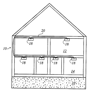
Fig. 1 illustrates a facility 10 having multiple levels 12, 14 and 16
with rooms on each level. As illustrated, an adverse condition detector 18 is
located in each of the rooms of the facility 10 and the detectors 18 are
interconnected by a pair of common conductors 20. The plurality of adverse
condition detectors 18 can communicate with each other through the common
conductors 20.
In Fig. 1, each of the adverse condition detectors 18 is configured to
detect a dangerous condition that may exist in the room in which it is
positioned.
Generally speaking, the adverse condition detector 18 may include any type of
5
CA 02448951 2003-11-12
device for detecting an adverse condition for the given environment. For
example,
the detector 18 could be a smoke detector (e.g., ionization, photo-electric)
for
detecting smoke indicating the presence of a fire. Other detectors could
include
but are not limited to carbon monoxide detectors, aerosol detectors, gas
detectors
including combustible, toxic and pollution gas detectors, heat detectors and
the
like.
In the embodiment of the invention to be described, the adverse
condition detector 18 is a combination smoke and carbon monoxide detector,
although the features of the present invention could be utilized in many of
the other
detectors currently available or yet to be developed that provide an
indication to a
user that an adverse condition exists.
Referring now to Fig. 2, thereshown is a block diagram of the
adverse condition detector 18 of the present invention. As described, the
adverse
condition detector 18 of the present invention is a combination smoke and CO
detector.
The adverse condition detector 18 includes a central microprocessor
22 that controls the operation of the adverse condition detector 18. In the
preferred
embodiment of the invention, the microprocessor 22 is available from Microchip
as
Model No. PICI6LF73, although other microprocessors could be utilized while
operating within the scope of the present invention. The block diagram of Fig.
2 is
shown on an overall schematic scale only, since the actual circuit components
for
the individual blocks of the diagram are well known to those skilled in the
art and
form no part of the present invention.
As illustrated in Fig. 2, the adverse condition detector 18 includes an
alarm indicator or transducer 24 for alerting a user that an adverse condition
has
been detected. Such an alarm indicator or transducer 24 could include but is
not
limited to a horn, a buzzer, siren, flashing lights or any other type of
audible, visual
or other type of indicator that would alert a user of the presence of an
adverse
condition. In the embodiment of the invention illustrated in Fig. 2, the
transducer
24 comprises a piezoelectric resonant horn, which is a highly efficient device
6
CA 02448951 2003-11-12
capable of producing an extremely loud.(85 dB) alarm when driven by a
relatively
small drive signal.
The microprocessor 22 is coupled to the transducer 24 through a
driver 26. The driver 26 may be any suitable circuit or circuit combination
that is
capable of operably driving the transducer 24 to generate an alarm signal when
the
detector detects an adverse condition. The driver 26 is actuated by an output
signal
from the microprocessor 22.
As illustrated in Fig. 2, an AC power input circuit 28 is coupled to
the line power within the facility. The AC power input circuit 28 converts the
AC
power to an approximately 9 volt DC power supply, as indicated by block 30 and
referred to as Vcc. The adverse condition detector 18 includes a green AC LED
34
that is lit to allow the user to quickly determine that proper AC power is
being
supplied to the adverse condition detector 18.
The adverse condition detector 18 further includes an AC test circuit
36 that provides an input 38 to the microprocessor 22 such that the
microprocessor
22 can monitor for the proper application of AC power to the AC power input
circuit 28. If AC power is not available, as determined through the AC test
circuit
36, the microprocessor 22 can switch to a low-power mode of operation to
conserve energy and extend the life of the battery 40. The adverse condition
detector 18 includes a voltage regulator 42 that is coupled to the 9 volt Vcc
30 and
generates a 3.3 volt supply VDD as available at block 44. The voltage supply
VDD
is applied to the microprocessor 22 through the input line 32, while the power
supply Vcc operates many of the detector-based components as is known.
In the embodiment of the invention illustrated in Fig. 2, the adverse
condition detector 18 is a combination smoke and carbon monoxide detector. The
detector 18 includes a carbon monoxide sensor circuit 46 coupled to the
microprocessor 22 by input line 48. In the preferred embodiment of the
invention,
the CO sensor circuit 46 includes a carbon monoxide sensor that generates a
carbon monoxide signal on input line 48. Upon receiving the carbon monoxide
signal on line 48, the microprocessor 22 determines whether the sensed level
of
7
CA 02448951 2003-11-12
carbon monoxide has exceeded one of many different combinations of
concentration and exposure time (time-weighted average) and activates the
transducer 24 through the driver 26 as well as turning on the carbon monoxide
LED 50. In the preferred embodiment of the invention, the carbon monoxide LED
50 is blue in color, although other variations for the carbon monoxide LED are
contemplated as being within the scope of the present invention.
In the preferred embodiment of the invention, the microprocessor 22
generates a carbon monoxide alarm signal to the transducer 24 that is distinct
from
the alarm signal generated upon detection of smoke. The specific audible
pattern
of the carbon monoxide alarm signal is an industry standard and is thus well
known
to those skilled in the art.
In addition to the carbon monoxide sensor circuit 46, the adverse
condition detector 18 includes a smoke sensor 52 coupled to the microprocessor
through a smoke detector ASIC 54. The smoke sensor 52 can be either a
photoelectric or ionization smoke sensor that detects the presence of smoke
within
the area in which the adverse condition detector 18 is located. In the
embodiment
of the invention illustrated, the smoke detector ASIC 54 is available from
Allegro
as Model No. A5368CA and has been used as a smoke detector ASIC for
numerous years.
When the smoke sensor 52 senses a level of smoke that exceeds a
selected value, the smoke detector ASIC 54 generates a local smoke alarm
signal
along line 56 that is received within the central microprocessor 22. Upon
receiving
the local signal, the microprocessor 22 generates an alarm signal to the
transducer
24 through the driver 26. The alarm signal generated by the microprocessor 22
has
a pattern of alarm pulses followed by quiet periods to create a pulsed alarm
signal
as is standard in the smoke alarm industry. The details of the generated alarm
signal will be discussed in much greater detail below.
As illustrated in Fig. 2, the adverse condition detector 18 includes a
hush circuit 58 that quiets the alarm being generated by modifying the
operation of
the smoke detector ASIC 54 upon activation of the test switch 60. If the test
8
CA 02448951 2011-05-30
switch 60 is activated during the generation of the local alarm signal upon
smoke
detection by the smoke sensor 52, the microprocessor 22 will output a signal
on
line 62 to activate the hush circuit 58. The hush circuit 58 adjusts the smoke
detection level within the smoke detector ASIC 54 for a selected period of
time,
referred to as the hush period, such that the smoke detector ASIC 54 will
moderately change the sensitivity of the alarm-sensing threshold for the hush
period. The use of the hush circuit 58 is well known and is described in U.S.
Patent No. 4,792,797 and RE33,920.
At the same time the microprocessor 22 generates the smoke alarm
signal to the transducer 24, the microprocessor 22 activates LED 64 and
provides a
visual indication to a user that the microprocessor 22 is generating a smoke
alarm
signal. Thus, the smoke LED 64 and the carbon monoxide LED 50, in addition to
the different audible alarm signal patterns, allow the user to determine which
type
of alarm is being generated by the microprocessor 22. The detector 18 further
includes an optional low-battery LED 66.
When the microprocessor 22 receives the local smoke alarm signal
on line 56, the microprocessor 22 generates an interconnect signal through the
I/O
port 72. In the preferred embodiment of the invention, the interconnect signal
is
delayed after the beginning of the alarm signal generated to activate the
transducer
24. However, the interconnect signal could be simultaneously generated with
the
alarm signal while operating within the scope of the present invention.
The I/O port 72 is coupled to the common conduit 20 (Fig. 1) such
that multiple adverse condition detectors 18 can receive the interconnect
signal
generated by the adverse condition detector that generates the local alarm
signal
upon actual detection of an adverse condition. Upon receiving the interconnect
signal, each of the adverse condition detectors generates the alarm signal
simultaneously. Thus, the multiple adverse condition detectors 18 can be
joined to
each other and sent into an alarm condition upon detection of an adverse
condition
by any of the adverse condition detectors 18.
9
CA 02448951 2003-11-12
Referring back to Fig. 2, the adverse condition detector 18 includes
both a digital interconnect interface 74 and a legacy interconnect interface
76 such
that the microprocessor 22 can both send and receive two different types of
signals
through the I/O port 72. The digital interconnect interface 74 is utilized
with a
microprocessor-based adverse condition detector 18 and allows the
microprocessor
22 to communicate digital information to other adverse condition detectors
through
the digital interconnect interface 74 and the I/O port 72.
As an enhancement to the adverse condition detector 18 illustrated in
Fig. 2, the legacy interconnect interface 76 allows the microprocessor 22 to
communicate to so-called "legacy alarm" devices. The prior art legacy alarm
devices are designed using an ASIC chip, such as Model No. A5368CA available
from Allegro, and issue a continuous DC voltage along the interconnect common
conductors 20 to any interconnected remote device during a local alarm
condition.
In the event that a microprocessor-based detector 18 is utilized in the same
system
with a prior art legacy device, the legacy interconnect interface 76 allows
the two
devices to communicate over the I/O port 72.
A test equipment interface 78 is shown connected to the
microprocessor 22 through the input line 80. The test equipment interface 78
allows test equipment to be connected to the microprocessor 22 to test various
operations of the microprocessor and to possibly modify the operating
instructions
contained within the microprocessor 22.
An oscillator 82 is connected to the microprocessor 22 to control the
internal clock within the microprocessor 22, as is conventional.
During normal operating conditions, the adverse condition detector
18 includes a push-to-test switch 60 that allows the user to test the
operation of the
adverse condition detector 18. The push-to-test switch 60 is coupled to the
microprocessor 22 through input line 84. When the push-to-test switch 60 is
activated, the voltage VDD is applied to the microprocessor 22. Upon receiving
the
push-to-test switch signal, the microprocessor generates a test signal on line
86 to
CA 02448951 2003-11-12
the smoke sensor via chamber push-to-test circuit 88. The push-to-test signal
also
generates appropriate signals along line 48 to test the CO sensor and circuit
46.
The chamber push-to-test circuit 88 modifies the output of the smoke
sensor 52 such that the smoke detector ASIC 54 generates a smoke signal 56 if
the
smoke sensor 52 is operating correctly, as is conventional. If the smoke
sensor 52
is operating correctly, the microprocessor 22 will receive the smoke signal on
line
56 and generate a smoke alarm signal on line 90 to the transducer 24.
Referring now to Fig. 3a, thereshown is the standard format for a
local audible alarm signal 99 generated by the adverse condition detector upon
generation of a level of smoke above a threshold value. Such a standard format
is
the ISO 8201:1987 audible emergency evacuation signal. As illustrated, the
local
alarm signal 99 has a repeating alarm cycle 90 that includes three alarm
pulses 92,
94 and 96 each having a pulse duration of 0.5 seconds and separated from each
other by an off time of 0.5 seconds. After the third alarm pulse 96, the
temporal
alarm signal has an off period 98 of approximately 1.5 seconds such that the
alarm
cycle 90 has a total alarm duration of approximately 4.0 seconds. After the
completion of the first alarm cycle 90, the alarm cycle 90 repeats to define
the
temporal pattern of the local alarm signal 99. In Fig. 3a, the alarm signal 99
is
shown being generated by the adverse condition detector that is actually
sensing
the adverse condition. This adverse condition detector will be referred to as
the
local detector for the remainder of the discussion to follow.
Referring now to Fig. 3b, thereshown is the legacy interconnect
signal 102 generated by the local detector at the same time that the local
detector is
generating the local alarm signal 99. The legacy interconnect signal 102 has a
high
level 104 sent to each of the interconnected adverse condition detectors along
the
common conductors 20. As illustrated in Fig. 2, when an adverse condition
detector is a "remote" (non-sensing) unit, the remotely generated interconnect
signal shown in Fig. 3b is received on the I/O port 72 and transmitted to the
microprocessor 22 through the legacy interconnect interface 76. Alternatively,
a
digital interconnect signal may be transmitted along the common conductors 20
11
CA 02448951 2003-11-12
and be received via the digital interconnect interface 74, depending upon the
type
of adverse condition detector generating the interconnect signal 102.
When the interconnect signal 102 of Fig. 3b is at the high level 104,
each of the remote interconnected adverse condition detectors that receives
the
interconnect signal begins to generate an audible alarm signal 103 (Fig. 3c)
having
generally the same alarm cycle 90 and series of alarm pulses 92-96 as the
local
alarm signal 99 shown in Fig. 3a. The interconnected adverse condition
detectors
that are not generating the local alarm signal will be referred to as remote
detectors
throughout the remainder of the present disclosure.
The interconnect signal 102 remains at the high level 104 for the
entire duration that the local detector senses the adverse condition and is
generating
the local alarm signal. Once the local detector no longer senses the adverse
condition, the local detector terminates generation of the local alarm signal
and the
interconnect signal 102 falls from the high level 104 to a grounded, low
level.
When the interconnect signal falls to the grounded low level, each of the
remote
detectors ceases to generate the audible alarm signal. This type of operation
has
been well known for many years and is a standard method of operating joined
adverse condition detectors utilizing an interconnect signal, and thus has
been
referred to as a "legacy" interconnect signal.
During the period of time that all of the adverse condition detectors
coupled to each other in the alarm system are simultaneously generating an
alarm
signal, the occupant is alerted to the presence of an adverse condition at one
of the
adverse condition detectors. As previously described, it is desirable to allow
the
occupant to more easily identify which of the actual adverse condition
detectors is
sensing the adverse condition during the generation of the alarm signal by all
of the
devices.
Fig. 4 is an illustration of the alarm signal 99 generated by the local
detector upon detection of an adverse condition. The alarm signal 99 shown in
Fig.
4 is a duplicate of the alarm signal shown in Fig. 3a and is reproduced for
the ease
of illustration, as will be described in detail below.
12
CA 02448951 2003-11-12
Referring now to Fig. 5, thereshown is a representation of the signal
on line 84 of the adverse condition detector 18 of Fig. 2. Line 84 extends
from the
push-to-test switch 60 and is received at an input pin to the microprocessor
22.
During normal operating conditions, line 84 is at ground level and no signal
is
being received at the microprocessor 22.
As illustrated in Fig. 5, if the user actuates the test switch 60 on any
of the remote adverse condition detectors 18 during the generation of the
alarm
signal 99 by the local detector, as shown in Fig. 4, a test pulse 106 is
generated.
Upon generation of the test pulse 106, the alarm system of the present
invention
enters into a Temporary Alarm Locate with Intermittent Warning (TAL w/IW)
condition that allows the user to audibly identify which of the adverse
condition
detectors is actually sensing the adverse condition while still periodically
alerting
the user to the presence of an adverse condition. In accordance with the
present
invention, the TAL w/IW period is controlled by controlling the level of the
interconnect signal, thereby disabling the generation of the audible alarm
signal
from all of the remote detectors while allowing the local detector to continue
to
generate the alarm signal.
In accordance with the present invention, the exact electrical nature
of the interconnect signal 102, as well as control over the interconnect
signal 102
being sent from the local detector to the remote detectors, can be exerted in
many
different manners depending upon the physical configuration of the adverse
condition detectors utilized in the alarm system. Regardless of how the
control
over the interconnect signal 102 is exerted, the overriding consideration of
the
present invention is the suspension of activation of the audible alarm signal
by the
remote detectors while enabling the local detector to continue to generate the
alarm
signal.
Upon generation of the test pulse 106 as illustrated in Fig. 5, the TAL
w/IW interconnect signal 105 being transmitted to the interconnected adverse
condition detector falls to the low level 108, as illustrated in Fig. 6.
13
CA 02448951 2003-11-12
When the TAL w/IW interconnect signal 105 falls to the low level
108, the alarm signal being generated by each of the remote detectors will be
disabled, as indicated by the initial silence period 110 in Fig. 7. As
illustrated in
Fig. 5, the initial silence period 110 is for a period of approximately one
minute,
although the duration of the silence period is a matter of design choice.
During this
initial silence period 110, each of the remote detectors is inhibited from
generating
the alarm signal such that the only alarm signal being generated is by the
local
detector. Since the local detector is the detector sensing the adverse
condition and
is the only detector generating an alarm signal during this initial silence
period 110,
the user can easily identify which of the adverse condition detectors is
sensing the
adverse condition by listening for the single adverse condition detector
generating
the alarm signal.
Referring back to Figs. 4 and 7, the test pulse warning 106 on a
remote detector serves as the beginning of a Temporary Alarm Locate with
Intermittent Warning (TAL w/IW) period in which the local detector generates
the
local alarm signal for the continuous duration of the TAL w/IW period while
the
remaining remote detectors are allowed to generate the alarm signal for only
brief
periods of time during the TAL w/IW period. In the embodiment of the invention
being described, the Temporary Alarm Locate with Intermittent Warning (TAL
w/IW) period has a duration of ten minutes, although other durations of time
are
contemplated as being within the scope of the present invention.
Referring back to Fig. 7, the alarm locate period includes multiple
alarm interrupt cycles 112. In the embodiment of the invention illustrated,
the
alarm interrupt cycle 112 has a duration of approximately one minute, although
other durations are contemplated by the inventor.
As shown in Fig. 6, during the alarm interrupt cycle 112, the TAL
w/IW interconnect signal 105 is allowed to go to the high level 104 for an
enable
period 114 and is pulled to the low level 108 for a disable period 116. As
illustrated in Figs. 6 and 7, the disable period 116 has a duration of
approximately
52 seconds compared to the enable period duration of approximately eight
seconds.
14
CA 02448951 2003-11-12
Referring back to Fig. 7, daring the enable period 114, the remote
detectors are able to generate the series of pulses 92, 94 and 96 of the alarm
signal,
while the alarm signal is disabled during the disable period 116. In the
preferred
embodiment of the invention, the enable period 114 is selected to be a
multiple of
the alarm cycle 90 such that the alarm signal can be generated for at least
two
complete alarm cycles to maintain the integrity of the audible pattern of the
alarm
signal. For example, in the embodiment of the invention illustrated, the
audible
temporal alarm cycle 90 has a duration of four seconds, while the enable
period
114 has a duration of eight seconds. Thus, during enable period 114, the
remote
detectors are able to generate substantially two cycles of the alarm signal.
Although two cycles of the alarm signal are selected in the preferred
embodiment
of the invention, it is contemplated that the enable period 114 could have a
different length and enable the generation of a larger or smaller number of
alarm
cycles while operating within the scope of the present invention.
As illustrated in Figs. 4, 6 and 7, during each of the alarm interrupt
cycles 112, the local detector continues to generate the local alarm signal
99, while
each of the remote detectors generates the alarm signal 100 for only the
enable
periods 114. Since the enable period 114 is selected to be only a small
portion of
the alarm interrupt cycle 112, the remote detectors generate the alarm signal
100
for only brief periods of time, while the local detector continuously
generates the
local alarm signal 99.
As can be understood by the prior description, the remote detectors
continue to generate an audible alarm for the enable periods 114 during the
alarm
interrupt cycles 112. Thus, the home occupant cannot fall into a state of
complacency after causing the system to enter the Temporary Alarm Locate with
Intermittent Warning (TAL w/IW) mode. Instead, the home occupant is
continually reminded in a periodic manner of the detected adverse condition by
the
activation of all of the remote detectors.
As can be understood in Figs. 6 and 7, the alarm interrupt cycle 112
is repeated for the entire duration of the temporary alarm locate period,
although
CA 02448951 2003-11-12
only a portion of the alarm locate ,period is shown. After the expiration of
the
alarm locate period, each of the remote detectors will generate the alarm
signal
continuously if the local detector continues to detect the adverse condition.
Thus,
the generation of the alarm signal by the remote detectors is intermittently
disabled
for only the Temporary Alarm Locate with Intermittent Warning (TAL w/IW)
period.
In the above description, the beginning of the Temporary Alarm
Locate with Intermittent Warning (TAL w/IW) (temporary alarm locate) period is
initiated by activating the test switch on any of the remote detectors 18
during the
period of time that the remote detectors and the local detector are generating
the
alarm signal. As indicated in Fig. 5, the actuation of the test switch on any
of the
remote detectors 18 creates the test pulse 106 that begins the temporary alarm
locate period. It is contemplated that the test switch could also be located
remotely
from the detectors and connected to the alarm system.
In accordance with the present invention, if the test switch is actuated
by the occupant on the local detector rather than one of the remote detectors,
the
actuation of the test switch causes the microprocessor 22 to generate a signal
to the
hush circuit 58, which begins the hush period. If, for example, the level of
the
adverse smoke condition is below the adjusted sensitivity level of the smoke
detector ASIC 54, the local alarm signal 99 and the interconnect signal 102
will be
terminated such that all of the remote detectors will also cease generating
the alarm
signal. Thus, the entry into the temporary alarm locate period is controlled
by the
actuation of the test switch on any of the remote detectors, while activation
of the
test switch on the local detector (the detector sensing the adverse condition)
will
initiate the hush period.
In the embodiment of the invention illustrated in Fig. 2, the adverse
condition detector 18 is controlled by a microprocessor 22. The microprocessor-
based adverse condition detector 18 can be used in an interconnected system
having other adverse condition detectors utilizing a similar microprocessor
22, or
can be used in combination with older, less advanced adverse condition
detectors
16
CA 02448951 2003-11-12
that utilize an ASIC as the sole basis for the alarm function. In an ASIC-
based
adverse condition detector, the legacy interconnect signal 102 is a simple DC
level
as indicated in Fig. 3b.
As indicated in Fig. 2, the microprocessor-based adverse condition
detector 18 includes a legacy interconnect interface 76 that allows the
microprocessor 22 to communicate with ASIC-based "legacy" alarms. Further, the
microprocessor 22 is able to communicate to other microprocessor-based
detectors
through the digital interconnect interface 74 using a different form of
interconnect
signal. Thus, the adverse condition detector 18 is able to control the
activation of
the various types of alarm signals generated by remote alarm units through the
I/O
port 72.
Referring now to Fig. 8, thereshown is a schematic illustration of a
system of interconnected adverse condition detectors that operate in
accordance
with the present invention. The system includes a pair of legacy devices, or
ASIC-
based adverse condition detectors 11 8a and 11 8b and a pair of microprocessor-
based detectors 120a and 120b. The ASIC detectors 118a and 11 8b are coupled
to
the microprocessor-based detectors 120a and 120b by the common conductors 20,
as was illustrated in Fig. 1. Although the schematic of Fig. 8 illustrates two
microprocessor-based detectors and two ASIC detectors, it is contemplated that
the
system could be comprised of any combination of detector types while operating
within the scope of the present invention.
In a first operating example, assume that the microprocessor-based
detector 120a is the detector actually sensing the adverse condition. The
microprocessor-based detector 120a becomes the local detector and begins to
generate the local audible alarm signal 99 as illustrated in Fig. 3a. At the
same
time, the microprocessor-based detector 120a generates the interconnect signal
102
of Fig. 3b to the pair of ASIC detectors 118a and I18b through the legacy
interconnect interface 76 (Fig. 2) and the I/O port 72. Upon receiving the
interconnect signal 102, both of the remote ASIC detectors 118a and 11 8b
begin to
generate the audible alarm signal as shown in Fig. 3c.
17
CA 02448951 2003-11-12
At the same time, the loca'1 detector 120a generates a digital
interconnect signal to the other microprocessor-based detector 120b to control
the
generation of the audible alarm signal by the detector 120b. The digital
signal is
sent through the digital interconnect interface 74 and also through the I/O
port 72.
Upon receiving the digital interconnect signal, the remote detector 120b also
begins to generate the audible alarm signal.
During the generation of the alarm signal by all of the remote
devices, if the test switch on the remote microprocessor-based detector 120b
is
actuated, the remote detector 120b sends a digital signal to the local
detector 120a
to begin the TAL w/IW period. Upon receiving the signal, the local
microprocessor-based detector 120a utilizes internal programming to control
the
level of the interconnect signal 102 to define the alarm interrupt cycle 112,
including the enable period 114 and the disable period 116, as illustrated in
Fig. 6.
At the same time, the detector 120a sends the digital intelligent signal to
the other
microprocessor-based detector 120b only during the enable period 114, such
that
the detector 120b generates the alarm signal only during the enable period
114.
In a second operating condition, assume that the ASIC detector 118a
is the detector sensing the adverse condition. The ASIC detector 11 8a becomes
the
local detector and generates the audible alarm signal 99 illustrated in Fig.
3a. At
the same time, the local ASIC detector 118a generates the interconnect signal
102
of Fig. 3b that causes the remaining detectors 11 8b, 120a and 120b to also
generate
the audible alarm signal.
During the generation of the audible alarm signal by the remote
detectors, if the test switch 60 is actuated on either of the microprocessor-
based
detectors 120a or 120b, the internal programming of the microprocessor begins
the
TAL w/IW period. During the TAL w/IW period, the microprocessor seizes
control of the common conductors and thus the level of the interconnect
signal.
Specifically, the remote microprocessor-based detector 120a or 120b causes the
potential on the common conductors 20 to be ground (zero volts) during the
disable
periods 116 and allows the potential on the common conductors to reach the
high
18
CA 02448951 2003-11-12
level 104 during the enable periods 114,' as illustrated in Fig. 6. Thus, the
remote
microprocessor detector 120, upon which the test switch was actuated, controls
the
Temporary Alarm Locate with Intermittent Warning period for the system of
interconnected adverse condition detectors illustrated in Fig. 8.
In the above description, if the test switch is depressed on the remote
ASIC detector 11 8b instead of one of the microprocessor-based remote
detectors
120a or 120b, it is contemplated by the inventor that a unique circuit could
be
designed to exert control over the interconnect signal on the common
conductors
20. Referring now to Fig. 9, thereshown is a contemplated circuit for
controlling
the interconnect signal. As illustrated in Fig. 9, the ASIC-based adverse
condition
detector 118 includes a new ASIC 122 having a defined number of connection
pins, usually 16. Although integrated circuits can generally be manufactured
with
multiple pin numbers and configurations, the very specialized adverse
condition
detector industry has utilized an ASIC package with 16 pins for at least 25
years.
As a result, there are many infrastructures at both the ASIC manufacturer and
the
adverse condition detector manufacturer that would benefit from keeping the
ASIC
package with the same number of pins, specifically 16. Although adding one or
two pins to achieve additional functionality is always physically possible,
the
advantages of keeping the package size and previous functionality consistent
outweigh the benefits of the additional pins for the adverse condition
detector
ASIC. Consequently, Fig. 9, as described in the next paragraph, presents a
method
to multiplex the use of existing pins and existing functionality in order to
gain
additional novel functionality needed for the functionality of Temporary Alarm
Locate with Intermittent Warning in a legacy detector.
As illustrated in Fig. 9, pins 124, 126 and 128 are used to operate a
traditional horn circuit including a piezoelectric horn 130, as is
conventional. The
horn 130 is driven by the signals on pins 126 and 128 being out of phase.
Thus, a
constantly alternating condition of a high signal on pin 126 and a low signal
on pin
128, or a low signal on pin 126 and a high signal on pin 128, will cause the
horn
130 to operate. During periods of non-operation of the horn 130, the potential
on
19
CA 02448951 2003-11-12
pins 126 and 128 is at ground. Traditionally, the pins 126 and 128 are held at
ground during non-operation to help avoid the problem of silver electro-
migration
across the silver surface of the piezo disk that might otherwise occur during
a
constant voltage difference being applied to the horn 130.
In accordance with the invention, if the test switch on the legacy
ASIC-based detector 118 is depressed when the ASIC 122 is receiving the
interconnect signal, the internal programming of the ASIC will be operated to
control the level of the interconnect signal as follows. Initially, the
internal logic
on the remote ASIC-based detector 118 starts the timing of the Temporary Alarm
Locate with Intermittent Warning period.
As soon as the first enable period 114 in Fig. 7 terminates, the ASIC
122 generates a high signal on both pins 126 and 128. The high signals on pins
126 and 128 are fed into a NAND gate 132. The NAND gate 132 generates a low
signal at its output 134 which is applied to both terminals of a second NAND
gate
136. Upon receiving a pair of low inputs, the NAND gate 136 generates a high
output through resistor 138 to the base of transistor 140. When the transistor
140
receives the high signal at its base, the transistor 140 is saturated, which
grounds
the common conductor 20 through the transistor 140. Thus, upon generation of a
high signal at both pins 126 and 128, the common conductors 20 are clamped to
ground, which results in the low level 108 for the legacy interconnect signal
105
that is being generated by another interconnected adverse condition detector
during
the disable period 116, as illustrated in Fig. 6.
During the activation time of the Temporary Alarm Locate with
Intermittent Warning period, there exist time periods as shown in Fig 6 where
the
common conductors 20 are released from their grounded potential, so that all
remote legacy alarm devices can sound the appropriate alarm signal as shown in
114. Once the internal logic of the ASIC 122 determines that the disable
period
110 (during the first cycle of non-alarm) or 116 (during subsequent cycles of
non-
alarm) has ended, the output pins 126 and 128 momentarily return to zero volts
and
deactivate the transistor 140 through the NAND gates 132 and 136, which
CA 02448951 2003-11-12
correspondingly releases the common conductors 20. At this time the ASIC 122
drives piezo horn 130 with an appropriate signal, such that neither pin 126
nor 128
would be at a logic high level simultaneously. Therefore, the NAND gate 132
would still continue to output a high level at 134 while the piezo horn is
being
activated. After the common conductors have been released, all other
interconnected adverse condition detectors operate to generate the audible
alarm
signal, assuming that the interconnect signal from the original and initiating
adverse condition detector is still present. This repeating condition of
alternately
activating and deactivating both the piezo horn 130 and the common conductors
20
is generally illustrated by 112 in Fig. 6 and Fig 7., and happens for the
entire
duration of the Temporary Alarm Locate with Intermittent Warning period as
controlled by ASIC 122. In using this method of seizing and grounding the
common conductors 20, one legacy smoke alarm with circuitry as illustrated in
Fig.
9 can control the interconnect functionality of a network of interconnected
legacy
smoke alarms.
The above description of Fig. 9 is one embodiment of an operating
circuit that allows a "legacy device" driven by an ASIC to create the
temporary
alarm locate period by utilizing external circuitry. It should be understood
that the
specific configuration of the circuitry in Fig. 9 is only one embodiment of
the
invention and other alternate circuits operating within the scope of the
invention
could be utilized. However, the circuitry illustrated in Fig. 9 allows the
ASIC 122
to provide a Temporary Alarm Locate with Intermittent Warning control signal
by
utilizing two pins 126 and 128 that are currently used only to operate the
horn 130.
Thus, the otherwise fully utilized ASIC 122 can be used to generate a control
signal in addition to the piezo horn, that new signal being the Temporary
Alarm
Locate with Intermittent Alarm.
Various alternatives and embodiments are contemplated as being
within the scope of the following claims particularly pointing out and
distinctly
claiming the subject matter regarded as the invention.
21