Note: Descriptions are shown in the official language in which they were submitted.
CA 02448966 2003-11-12
Plastic Bag Making Apparatus
Field of the invention
The invention relates to an apparatus for successively making plastic
bags each of which has a shape of circumference.
Prior Art
There has been commercially available an apparatus for successively
making plastic bags each of which has a shape of circumference, as disclosed
in US-2001-0053737. The apparatus includes web feeding means by which a
web material is intermittently fed for a length along a longitudinal feeding
path. The web material comprises two or more layers of plastic film. The
apparatus further includes web cutting means disposed along the feeding
path. in the apparatus of the publication, the web material is cut partially
or
totally by the web cutting means whenever the web material is intermittently
fed and temporarily stopped, to successively make plastic bags with wastes
taken to pieces.
The apparatus is therefore problematic with respect to the wastes. In
the apparatus of the publication, the wastes are pulled by waste removing
means and torn from the web material to be removed. However, it is then
required to suitably collect and treat the wastes. fn addition, the wastes may
be too small to be pulled and torn by the waste removing means. The wastes
may be particular in shape which cannot be pulled and torn by the waste
removing means.
It is tfterefore an object of the invention to provide a new and
improved apparatus for successively making plastic bags each of which has a
shape of circumference, to overcome the above problems.
Other object of the invention is to provide the apparatus which can
successively make the plastic bags with a waste kept continuous to
1
CA 02448966 2003-11-12
conveniently treat the waste.
Summary of the Invention
According to the invention, the apparatus comprises web feeding
means by which a web material is intermittently fed for a length along a
longitudinal feeding path. The web material comprises two or more layers of
plastic film.
The apparatus further comprises web cutting means disposed along
the feeding path. The web cutting means has a shape corresponding
completely or incompletely to the shape of circumference of plastic bag so
that the web material can be cut into the shape of circumference of plastic
bag by the web cutting means whenever the web material is intermittently fed
and temporarily stopped, to successively make plastic bags with a waste kept
continuous.
The web cutting means comprises partially cutting means. The plastic
bag has an upstream edge a#ong which the web material is cut partia##y by the
partially cutting means so that the plastic bag can be kept connected with the
waste at the upstream edge of plastic bag.
The apparatus further comprises drawing means disposed
downstream of the cutting means. The waste is diverged from the plastic bag,
directed to and drawn by the drawing means after the web material is cut.
The apparatus further comprises discharge means disposed
downstream of the cutting means. The plastic bag is directed to the discharge
means without the waste. The plastic bag is then pulled by the discharge
means to be torn from the waste at the upstream of plastic bag. The plastic
bag is then discharged by the discharge means.
In a preferred embodiment, the web cutting means further comprises
tota#ly cutting means. The plastic bag has other edges along which the web
material is cut totally by the totally cutting means so that the plastic bag
can
2
CA 02448966 2003-11-12
be disconnected from the waste at other edges.
The apparatus further comprises heat seal means disposed upstream
of the cutting means. The web material is heat sealed longitudinally and .
widthwise thereof by the heat seal means whenever the web material is
intermittentiy fed and temporarily stopped so that heat sealed portions can be
formed tongitudinaiiy and widthwise of the web material, The web material is
then cut along the heat sealed portions by the web cutting means.
The web cutting means comprises THOMSON blade means opposed
to the web material. The apparatus further comprises drive means by which
the THOMSON blade means is moved toward and pressed against the web
material whenever the web material is intermittently fed and temporarily
stopped.
The partially cutting means has micro depressions formed and spaced
from each other along the cutting edges thereof to leave micro joints formed
and spaced from each other along the upstream edge of plastic bag. The
micro joints make the web material cut partially. The plastic bag is kept
connected with the waste by the micro joints.
The drawing means comprises take up means by which the waste is
drawn and taken up.
The apparatus further comprises waste guide means disposed
between the web cutting means and the discharge means. The waste is
engaged with and guided by the waste guide means to be changed in
direction, diverged from the plastic bag and directed to the drawing means so
that the plastic bag can be directed to the discharge means without the waste.
The apparatus further comprises detector means for detecting the
plastic bag to determine whether the plastic bag is inclined or not when the
waste is diverged from the plastic bag and tl2e plastic bag is directed to the
discharge means.
3
CA 02448966 2003-11-12
The apparatus further comprises rejected bag removing means
incorporated into the discharge means. The plastic bag is removed by the
removing means in response to a detecting signal fed from the detector
means when the plastic bag is inclined.
Brief Description of the Drawings.
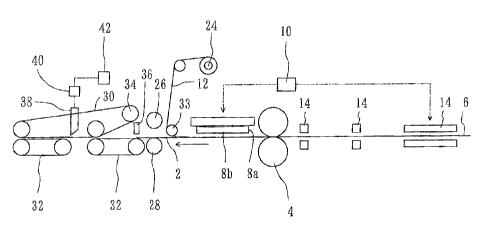
Fig. 1 is a side view of a preferred embodiment of the invention.
Fig. 2 is a plan view showing the plastic bags and the waste of Fig. 1.
Fig. 3 is a plan view of other embodiment.
Detailed Description of the preferred embodiment
Referring now to the drawings, Fig. 1 illustrates an apparatus for
successively making plastic bags 2 each of which has a shape of
circumference, according to the invention. The apparatus includes web
feeding means 4 by which a web material 6 is intermittently fed for a length
along a longitudinal feeding path. In the embodiment, the web feeding means
4 comprises a pair of feeding rollers between which the web material 6 is
sandwiched: The feeding rollers 4 are driven for rotation by drive means such
as a motor so that the web material 6 can be intermittently fed for the length
along the feeding path which extends horizontally. The web material 6
comprises two or more layers of plastic film.
The apparatus further includes web cutting means 8a and 8b disposed
along the feeding path. The web cutting means 8a and 8b comprises
THOMSON blade means opposed to the web material 6. The apparatus
further includes drive means 10 by which the THOMSON blade means 8a and
8b is moved toward and pressed against the web material 6 whenever the web
material 6 is intermittently fed and temporarily stopped. The THOMSON blade
means 8a and 8b has a shape corresponding completely to the shape of
circumference of plastic bag 2. Accordingly, the web material 6 can be cut
into the shape of circumference of plastic bag 2 by the TNOMSON blade
4
CA 02448966 2003-11-12
means 8a and 8b whenever the web material 6 is intermittently fed and
temporarily stopped, to successively make the plastic bags 2 with a waste 12
kept continuous. In the embodiment, the THOMSON blade means 8a and 8b
comprises a pair of THOMSON blades to successively make plastic bags two
by two, as shown in Fig. 2. The waste 12 is kept continuous around each of
the plastic bags 2. .
The apparatus further includes heat seal means 14 disposed upstream
of the THOMSON blades 8a and 8b. The heat seal means 14. comprises heat
seal bars which are moved toward and pressed against the web material 8 by
the drive means 10 to be synchronized with the THOMSON blades 8a and 8b.
The web material 6 is therefore heat seated longitudinally and widthwise
thereof by the heat seal bars 14 whenever the web material 6 is intermittently
fed and temporarily stopped so that heat sealed portions 1 B can be formed
longitudinally and widthwise of the web material 6. The web materiaC 6 is then
cut along the heat sealed portions 16 by the THOMSON blades 8a and 8b, to
successively make the plastic bags 2.
In addition, the THOMSON blades 8a and 8b comprise partially and
totally cutting means. The plastic bag 2 has an upstream edge 18 along which
the web material 6 is cut partially by the partially cutting means 8a. The
plastic bag 2 has other edges 20 and 21 along which the web material fi is cut
totally by the totally cutting means 8b so that the plastic bag 2 can be kept
connected with the waste 12 at the upstream edge 18 of plastic bag 2 and
disconnected from the waste 12 at other edges 20 and 21. In the embodiment,
the partially cutting means 8a has micro depression formed and spaced from
each other along the cutting edge thereof to leave micro joints 22 formed and
spaced from each other along the upstream edge 18 of plastic bag 2. The
micro joints 22 make the web material 6 cut partially. The plastic bag 2 is
kept
connected with the waste 12 by the micro joints 22. It should be recognized
b
CA 02448966 2003-11-12
that the micro joints 22 are shown in exaggeration for convenience. fn
reality,
each of the micro joints 22 has a very small size of about 0.2 mm.
The apparatus further includes drawing means 24 disposed
downstream of the THOMSON blades 8a and 8b. The waste 12 is diverged
from the plastic bag 2, directed to and drawn by the drawing means 24 after
the web material 6 is cut. The drawing means 24 comprises take up means by
which the waste 12 is drawn and taken up. For example, the drawing means
24 comprises a take up roller intermittently rotated whenever the web material
6 is intermittently fed so that the waste 12 can be drawn and taken up by the
take up roller 24 without slacking. The plastic bag 2 is kept connected with
the waste 12 at the upstream edge 18 of plastic bag 2, as described above,
and therefore intermittently 'fed integrally with the wasi:e 12. The waste 12
may be directed to and drawn by drawing means other than the take up roller
24. For example, the drawing means may comprise pinch rollers between
which the waste 12 is pinched. The pinch rollers are intermittently rotated
whenever the web material 6 is intermittently fed so that the waste 12 can be
drawn by the pinch rollers without slacking. ,
The apparatus further includes discharge means 26, 28, 30 and 32
disposed downstream of the THOMSON blades 8a and 8b. The discharge
means 26, 28, 30 and 32 comprises upper and lower rollers and upper and
lower belts. The plastic bag 2 is directed to the upper and lower rollers 26
and 28 without the waste 12. The plastic bag 2 is then pulled by the upper
and lower rollers 2& and 28 to be torn from the waste 12 at the upstream edge
18 of plastic bag 2. The plastic bag 2 is then discharged by the upper and
lower belts 30 and 32, as described below.
The apparatus further includes waste guide means 33 which
comprises a waste guide roller disposed between the THOMSON blades 8a
and 8b and the upper and lower rollers 26 and 28. The waste 12 is engaged
6
CA 02448966 2003-11-12
with and guided by the waste guide roller 33 to be changed in direction,
diverged from the plastic bag 2 and directed to the take up ro1(ar 24 so that
the plastic bag 2 can be directed to the upper and lower rollers 26 and 28 and
the upper and lower belts 30 and 32 without the waste 12. In the embodiment,
the waste i2 is changed in direction to extend upwardly from the waste guide
roller 33. The plastic bag 2 is directed along the feeding path of web
material
6 which extends horizontally. The waste 12 is therefore diverged from the
plastic bag 2 and directed to the take up roller 24 so that the plastic bag 2
can be directed to the upper and lower rollers 26 and 28 and upper and lower
belts 30 and 32 without the waste 12.
The plastic bag 2 is directed to and disposed between the upper and
lower rollers 26 and 28. The upper roller 26 is then moved toward the lower
roller 28 by the drive means 10 to be synchronous with the THOMSON blades
8a and 8b so that the plastic bag 2 can be sandwiched between the upper and
lower toilers 26 and 28 whenever the web material 6 is intermittently fed and
temporarily stopped. In addition, the lower roller 28 is driven for rotation
by
drive means such as a motor when the plastic bag 2 is sandwiched. The upper
roller 26 is therefore driven for rotation by lower roller 28. The lower
roller 28
is rotated counterclockwise in Fig. 1 while the upper roller 26 is rotated
clockwise so that the plastic bag 2 can be pulled by the upper and tower
rollers 26 and 28 to be torn from the waste 12 at the upstream edge 18 of
plastic bag 2.
The plastic bag 2 then passes through the upper and lower rollers 26
and 28 to be disposed between the upper and lower belts 30 and 32. The
upper belt 30 is engaged with a pulley 34 which is moved toward the lower
best 32 by the drive means 1 O when or after the plastic bag 2 is disposed
between the upper and lower belts 30 and 32. The plastic bag 2 is therefore
sandwiched between and discharged by the upper and lower belts 30 and 32.
7
CA 02448966 2003-11-12
Accordingly, the apparatus can successively make the plastic bags 2
with the waste 12 kept continuous. The waste 12 can therefore be taken up by
the take up roller 24, to conveniently treat the waste 12.
In addition, the plastic bag 2 may be bend or curved considerably to
be engaged with the Lower roller 28 at the downstream edge 21 of plastic bag
2 when the plastic bag 2 is directed to the upper and Ic~wer rollers 26 and
28.
The micro joints 22 may therefore be wrenched and torn by a friction between
the plastic bag 2 and the cower roller 28 so that the plastic bag 2 can be
inclined considerably. The plastic bag 2 may be inclined into a position shown
by chained line of Fig. 2 to be overlapped with the next bag 2. In this case,
the inclined bag 2 must be damaged by the THOMSON blades 8b when the
next bag 2 is cut.
Under the circumstances, the apparatus further includes detector
means 36 disposed downstream of the waste guide roller 33 'for detecting the
plastic bag 2 to determine whether the plastic bag 2 is inclined or not when
the waste 12 is diverged from the plastic bag 2 and the pEastic bag 2 is
directed to the upper and tower rollers 26 and 28. In thus embodiment, the
apparatus is arranged to successively make plastic bags 2 two by two, as
described above. In this connection, the detector means comprises a plurality
of detectors 36 to allot several detectors 36 to each of the plastic bags 2.
The
detectors 36 comprise optical sensors which are spaced from each other in a
direction perpendicular to the feeding path of web material 6 to be disposed
at positions corresponding to the downstream edge 21 of plastic bag 2. The
optical sensors 36 can therefore detect the plastic bag 2 to determine whether
the plastic bag 2 is inclined or not when the waste 12 is diverged from the
plastic bag 2 and the plastic bag 2 is directed to the upper and lower rollers
26 and 28.
The apparatus further includes rejected bag removing means 38
S
CA 02448966 2003-11-12
incorporated into the upper and lower belts 30 and 32. The plastic bag 2 is
removed by the removing means 38 in response to a detecting signal fed from
the optical sensor 36 when the plastic bag 2 is inclined. In the embodiment, a
plurality of belts 30 are used as upper belts while a plurality of belts 32
are
used as lower belts. In addition, the Power belts 32 are divided into upstream
and downstream belts. The removing means 38 comprises a stop disposed
between the upper belts 30 at a position between the upstream and
downstream belts 32. The stop 38 is moved downward by drive means 40
which is actuated by a control 42 in response to the detecting signal fed from
the optical sensor 3fi when the plastic bag 2 is inclined. The inclined bag 2
then strike against the stop 38 when being discharged by the upper and lower
belts 30 and 32, to be dropped and removed between the upstream and
downstream belts 32.
The waste 12 may be cut along cut Fines 4A. by cutter means after the
plastic web 6 is cut by the TNOMSON blades 8a and 8b so that the waste 12
can be divided widthwise of the web material 6 and taken up by the take up
roller 24.
The web material 8 may be slit along slit fines 4B by slit blades before
being cut by the TNOMSON blades, as shown in Fig. 3. fn this case, the web
material 6 needs merely to be cut along the upstream and downstream edges
18 and 21 of plastic bag 2 by the TNOMSON blades whenever the web
material 6 is intermittently fed and temporarily stopped. The web material 6
needs not to be cut along other edges 20 by reason that the web material 6
has been slit along the slit lines 46 or other edges 20. The THOMSON blades
may therefore have a shape corresponding not completely but incompletely to
the shape of circumference of plastic bag 2.
In this connection, it should be recognized that the plastic bag 2
comprises two or more layers of plastic film which are liable to adhere to
each
9
CA 02448966 2003-11-12
other when being cut by the THOMSaN blades. On the other hand, the layers
of plastic film do not adhere to each other when being slit by the slit
blades.
The plastic bag 2 may include open top and closed bottom edges comprising
other edges 20 along which the web material 6 is slit. It is therefore
advantageous in that the open top edge is easy to be open when filling
content into the plastic bag after making the plastic bag.