Note: Descriptions are shown in the official language in which they were submitted.
CA 02449045 2003-11-28
WO 02/101410 PCT/IT02/00378
TRANSPONDER HAVING HIGH PHASE STABILITY, PARTICULARLY
FOR SYNTHETIC APERTURE RADAR OR SAR SYSTEMS
This invention relates to a high phase stability transceiver or
transponder particularly useable in Synthetic Aperture Radar (or SAR)
apparatuses, which, upon receiving a signal, enables in reliable, simple
and efficient way , to transmit an amplified signal having the same
frequency as the received signal and a time stable phase relationship with
it, said transponder turning out to be extremely inexpensive and to have
extrerraely reduced dimensions.
It is known that a synthetic aperture radar or SAR apparatus is
a microwave active distance survey apparatus that is installed on board of
aircraft or satellites and enables high resolution images of the observed
scene to be generated, regardless of the meteorologic conditions or of the
presence of sun light. Generally the wavelength of the microwaves utilised
in such a SAR system is in the range of 3 cm to 30 cm.
The survey resolution substantially depends on the frequency
of transmitted radar signal, on the aperture of the antenna beam. as well
as on the distance between the radar system and the surface to be
surveyed.
In all those applications requiring a continuous monitoring
operation, such as the Ground Motion Monitoring, the radar system is
preferably installed on board of a satellite. In spite of the great range at
which such a radar system operates, equal to about 800 km, the SAR
technology allows a high spatial resolution to be achieved by means of a
processing operation carried out on the echo signal reflected from the
surface irradiated by the transmitted signal. In particular, such processing
operation perfiorms a focalisation of the image that synthesises the
reflected echo signal in order to simulate an antenna aperture having a
noticeably enlarged dimension with respect to the antenna as effectively
installed on board of the aircraft.
One of the characteristics of a SAR system is its capability to
track both the amplitude behaviour and the phase behaviour of the back
reflected echo signal. In those cases in which two SAR images of the
same scene are obtained from slightly different observation angles,
thereby forming a so called stereoscopic pair or "stereo pair", their phase
difference, which generates their interference fringes, can be
CA 02449045 2003-11-28
WO 02/101410 PCT/IT02/00378
2
advantageously exploited for generating Digital Elevation Maps or DEMs
in order to monitor the terrain variations and to improve the distance
resolution or range.
In some applications, such as the Ground Motion Monitoring,
the presence of permanent targets or PT on the surveyed territory enables
any terrain variations to be detected by analysing time sequences of the
images obtained from the same scene. Such Permanent Targets have
radio diffusion properties that are known to the SAR system and that are
maintained stable in the time. In particular, the technique utilising such
PTs, that can be both artificial and natural, is designated as external
calibration.
The present conventional PTs are passive devices, among
which the most generally utilised are the ones known to those skilled in
the art as "corner reflectors", particularly the triangular trihedron ones.
Each device covers a geometric area much smaller than a single
resolution cell of the scene. Aiming a minimising the errors caused by the
noise generated by the surrounding environment, the radar echo section
or RCS (Radar Cross Section) of the PT should be by at least 20 dB
higher than the total power diffused by the corresponding resolution cell of
the SAR image.
Said passive corner reflectors have noticeable external
dimensions and weight and, therefore, this causes some drawbacks.
In the first place, said passive corner reflectors make the
repeatibility of the antenna direction particularly complex.
In addition, the required realisation tolerances of said passive
corner reflectors are very severe.
Furthermore, the dimension variations due for instance to
thermal variations jeopardise the detection accuracy of the concerned
SAR system.
Lastly, the scarce manoeuvrability of the passive corner
reflectors complicates their installation on the territory to be surveyed and
prohibits their exploitation in all those applications which require a large
number of such devices to be used.
In order to reduce the weight and the complexity of the
Permanent Targets, a possible alternative is based upon use of an active
antenna transponder.
CA 02449045 2003-11-28
WO 02/101410 PCT/IT02/00378
3
In any case, the specific application requires that the re-
transmitted signal have the same frequency as the received signal and
have a time stable phase relationship with the received signal and further
that the receive antenna and the transmit antenna have such a pointing
direction as to substantially cover the same space portion: this made the
realisation of such a passive PT up to now extremely complex and
expensive.
It is an object of this invention, therefore, to provide an active
antenna transponder having reduced dimensions, adapted to be utilised
as an active PT, thereby enabling in reliable, simple and inexpensive way
to transmit an amplified signal having the same frequency as the received
signal and a time stable phase relationship with the received signal, with
irradiation of the transmitted signal in the same direction from which the
received signal arrives.
It is specific subject matter of this invention a transceiver or
transponder particularly for synthetic aperture radar, or SAR, systems,
operating in a frequency band having a central frequency, said
transponder comprising a receiver and a transmitter both thermally stable
and realised by microstrip technology, said receiver and said transmitter
being adapted to receive and to transmit, respectively, an electromagnetic
wave provided with at least one linear polarisation, said receiver being
connected to said transmitter by amplifier means comprising an amplifier
unit for each linear polarisation of the wave received by said receiver,
each amplifier unit including at least two amplifier stages cascade
arranged along a single microstrip and interconnected to one another and
to an input and to an output of the corresponding amplifier unit by means
of coupling or matching stages, the output signal of each amplifier unit
having substantially the same frequency as the input signal thereto, said
amplifier units having substantially the same gain, said gain being no
lower than 25 dB, said transponder being phase stable so that each linear
polarisation of the transmitted electromagnetic wave has phase variations
in time no higher than 20°, said transponder further comprising
electromagnetic decoupling means between said transmitter and said
receiver.
Preferably, according to this invention, the transponder is
phase stable so that each linear polarisation of the transmitted
CA 02449045 2003-11-28
WO 02/101410 PCT/IT02/00378
4
electromagnetic wave has phase variations in the time no higher than
15°.
Also according to this invention, said amplifier means comprise
a band pass filter realised in microstrip technology, connected to the input
of each amplifier unit.
Again according to this invention, each band pass filter has a
pass band no less than 10% of the central frequency of the operation
band of said transponder, more preferably no less than 15% of the central
frequency of the operation band of said transponder and even more
preferably no less than 20% of the central frequency of the operation
band of said transponder.
Further according to this invention, each band pass filter
introduces an attenuation no higher than 5 dB and more preferably no
higher than 2 dB.
Again according to this invention, said amplifier means have a
phase stability such that the output signal of each amplifier unit has phase
variations in time no higher than 15°, preferably no higher than
9°.
Further according to this invention, the amplifier units can have
a gain no lower than 35 dB, preferably no lower than 40 dB.
Additionally according to this invention, said amplifier means
can have a Noise Figure or NF value no higher than 5 dB, preferably no
higher than 2 dB.
Preferably, according to this invention, said receiver and said
transmitter have a frequency band of no less than 10% of the central
frequency of the operation band of said transponder, more preferably no
less than 15% of the central frequency of the operation band of said
transponder and even more preferably no less than 20% of the central
frequency of the operation band of said transponder.
Still according to this invention, said receiver can have such a
phase stability as to introduce into the received electromagnetic wave a
phase variation in time of no more than 5°, preferably of no more than
3°,
and said transmitter can have such a phase stability that the transmitted
electromagnetic wave has a phase variation in time of no more than 5°,
preferably of no more than 3°.
Again according to this invention, the transponder can be
adapted to operate at temperature values in the range of -40°C to
+80°C.
CA 02449045 2003-11-28
WO 02/101410 PCT/IT02/00378
Preferably according to this invention, said receiver and said
transmitter each comprise at least one micro strip radiating element or
patch, arranged on a support surface made of a thermally stable material.
Further according to this invention, said receiver and said
5 transmitter can each comprise a single patch.
Still according to this invention, said receiver and said
transmitter can each comprise a square array of 2 x 2 patches.
Again according to this invention, said support can be realised
of a laminated dielectric dual-plated material, preferably comprising
Duroid.
Further according to this invention, at least one amplifying
stage can include a pseudomorphic high electron mobility transistor
(PHEMT) stage.
Still according to this invention, at least one matching stage
can include a coupling network.
Again according to this invention, at least one matching stage
can include a 50 ohm planar coupling line.
Preferably according to this invention, said amplifier means are
directly integrated at the output of said receiver, so that each amplifier
unit is directly integrated on each connection microstrip between a
corresponding output of said receiver and a corresponding input of said
transmitter.
Additionally according to this invention, each band pass filter
can be directly integrated on said microstrip of the corresponding amplifier
unit.
Further according to this invention, each amplifier unit can
include three amplifying stages.
Again according to this invention, each amplifier unit can
include four amplifying stages.
Still according to this invention, said transponder can have a
radar cross section or RCS figure of no less than 20 dBsqm, preferably of
no less than 25 dBsqm, more preferably of no less than 30 dBsqm and
even more preferably of no less than 34 dBsqm.
Further according to this invention, the receiver and/or the
transmitter can have an antenna gain in the range of 6 dBi to 13 dBi.
Preferably according to this invention, said transponder
operates in class C.
CA 02449045 2003-11-28
WO 02/101410 PCT/IT02/00378
6
Further according to this invention, the transponder can be
provided with a power supply comprising a digital control unit adapted to
periodically activate said transponder only for a limited time duration.
Again according to this invention, said power supply can be
provided with one or more long duration or low discharge batteries.
Still according to this invention, said power supply can be
provided with one or more solar cells.
According to this invention, said de-coupling means between
said transmitter and said receiver can include at least one metal
diaphragm.
Still according to this invention, said de-coupling means
between said transmitter and said receiver can further include one or
more radio frequency signal absorber panels adapted to absorb the
radiation irradiated from said transmitter to said receiver.
Further according to this invention, said absorber panels can
be laterally and parallel arranged with respect to said at least one metal
diaphragm.
Again according to this invention, said de-coupling means
between said transmitter and said receiver include at least a portion of a
radome realised with a material having a negligible impact on the
radiative properties of said receiver and of said transmitter at the
operation frequencies as well as a shape and a thickness adapted to
make the reflection of the wave irradiated from said transmitter to said
receiver substantially negligible.
Preferably according to this invention, the material of said
portion of the radome comprises fibre glass and/or Teflon.
Further according to this invention, said portion of the radome
can have a cylindrical sector shape with an angular width a no greater
than 90°, preferably no greater than 60°.
Additionally according to this invention, said portion of the
radome has a thickness no greater than 0.5 mm, preferably no greater
than 0.2 mm.
This invention will be now described by way of illustration, not
by Way of limitation, according to its preferred embodiments, by
particularly referring to the Figures of the annexed drawings, in which:
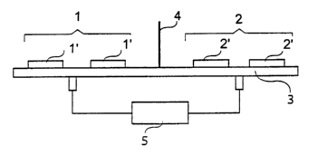
Figure 1 shows a top plan view of a first embodiment of the
transponder according to this invention,
CA 02449045 2003-11-28
WO 02/101410 PCT/IT02/00378
7
Figure 2 shows a front view of the transponder of Figure 1,
Figure 3 shows a circuit block diagram of the amplifier unit in
the transponder of Figure 1,
Figure 4 shows a front view of a second embodiment of the
transponder according to this invention,
Figure 5 shows a graph of the gain behaviour of the amplifier
unit in the transponder of Figure 1 as a function of the frequency,
Figure 6 shows a first graph of the behaviour of the S
parameters of the amplifier unit of Figure 1 as a function of the frequency,
Figure 7 shows a second graph of the behaviour of the S
parameters of the amplifier unit of Figure 1 as a function of the frequency,
Figure 8 shows a cross-section view of the transponder of
Figure 1, including the radome,
Figure 9 shows a graph of the frequency behaviour of the
return losses as measured for the transmitter of the transponder of Figure
1,
Figure 10 shows a graph of the frequency behaviour of the
return losses as measured for the receiver of the transponder of Figure 1,
Figure 11 shows a graph of the frequency behaviour of the
coupling between the transmitter and the receiver in the transponder of
Figure 1,
Figure 12 shows a graph showing the behaviour of the phase
shift introduced by the amplifier means as a function of the temperature
variations in a third embodiment of the transponder according to this
invention,
Figure 13 shows a graph of the frequency behaviour of the
relative insertion losses of the amplifier means of the third embodiment of
the transponder according to this invention,
Figure 14 shows a graph of the frequency behaviour of the
coupling between the transmitter and the receiver of the third embodiment
of the transponder according to this invention,
Figure 15 shows an image from the satellite which compares a
conventional passive PT to the third embodiment of the transponder
according to this invention.
The same reference numerals will be utilised in the following
description to designate the same items in the Figures.
CA 02449045 2003-11-28
WO 02/101410 PCT/IT02/00378
8
By referring now to Figures 1 and 2, it can be observed that the
first embodiment of the transponder according to this invention comprises
a receiver 1 and a transmitter 2, both realised in microstrip technology,
operating with large band, preferably in band C centred on a frequency of
5.3 GHz. Receiver 1 and transmitter 2 each comprise a 2 x 2 array of
microstrip radiating elements, or patches, 1' and 2', respectively, arranged
upon the surface of a rectangular support member 3, realised in thermally
stable material, preferably dielectric laminated dual-plated material, even
more preferably comprising Duroid. Receiver 1 and transmitter 2 are
adapted to receive and to transmit, respectively, a linearly polarised
electromagnetic wave. Preferably, said receiver 1 and said transmitter 2
have an antenna gain value in the range of 6 dBi to 18 dBi, more
preferably equal to 16 dBi. Support member 3 is provided with a metal
diaphragm 4 adapted to decouple said receiver 1 and said transmitter 2
from one another, since they operate at the same operation frequency
and, therefore, they ought to be separated from one another in order to
prevent any oscillation effect; preferably, the height of said diaphragm is
in the range of 3 cm to 7 cm, as a function of the arrays of said receiver 1
and of said transmitter 2 as well as of their distance from one another.
Receiver 1 is connected to transmitter 2 by means of an
amplifier unit 5 having high phase stability. By referring to Figure 3, it can
be observed that amplifier unit 5 is realised by arranging three cascade
connected amplifier stages upon a single microstrip, interconnected with
one another by suitable coupling or matching stages. In particular, said
amplifier unit 5 comprises the following cascade connected components:
- an input coupling network 6,
- a first amplifier stage 7, realised in pseudomorphic high
electron mobility transistor (or PHEMT) technology;
- an interstage coupling network 8, equal to the input coupling
network;
- a second amplifier stage 9;
- a 50 ohm planar coupling line 10;
- a third amplifier stage 11; and
- an output 50 ohm planar coupling line, equal to the above
quoted planar line 10.
Considered as a whole, said amplifier unit 5 has a noise figure
or NF no higher than 2 dB and a gain value no lower than 40 dB.
CA 02449045 2003-11-28
WO 02/101410 PCT/IT02/00378
9
By referring to Figure 4, it can be observed that, in a second
embodiment of the transponder according to this invention, said amplifier
unit 5 is directly integrated at the output of said receiver 1 on a microstrip
connecting this receiver to transmitter 2.
Figure 5 illustrates the behaviour of the gain of said amplifier
unit 5 as a function of the frequency, while Figures 6 and 7 illustrate,
respectively, the behaviour of the S-parameters of said amplifier unit 5 as
a function of the frequency, in the frequency range of 4 GHz to 6 GHz and
in the range of 5.2 GHz to 5.4 GHz, respectively. It is evidenced that
parameter s2~ appears to be particularly stable in the range of the
operation frequency of 5.3 GHz. Furthermore, the phase shift of said
parameter s2~ when the temperature varies in the range of -30°C to
+60°C
is lower less than 0.8°.
By referring to Figure 8, it can be observed that the
transponder according to this invention further comprises a radome 13
realised with a material having a negligible impact on the radiative
properties of the receiver 1 and transmitter 2 arrays at the operation
frequencies. According to the preferred embodiment of the transponder,
the material for said radome 13 comprises fibre glass and/or Teflon.
Furthermore, the concerned radome 13 ought to have a shape and a
thickness adapted to minimise the reflection of the wave irradiated from
the transmitter 2 to the receiver 1, in order to maintain an high decoupling
relation therebetween. According to the preferred embodiment of the
transponder, said radome 13 comprises a first portion 14 having the
shape of a cylindrical sector with an angular width a no larger than
90°,
even more preferably no larger than 60°, rigidly connected to a second
portion 15, having a rectangular cross-section, intended for resting on
said support member 3. Preferably, the thickness of said first portion 14 is
no higher than 0.5 mm and even more preferably it is no higher than 0.2
mm. Advantageously, the shape of the radome is adapted to prevent any
atmospheric materials, such as snow or rain, from accumulating on the
radome surface through which the electromagnetic waves interacting with
said receiver 1 and said transmitter 2 are passed.
The transponder according to this invention has such a phase
stability as to introduce phase shifts depending on the temperature
variations no higher than 20°, preferably no higher than 15°,
and a CS
figure no lower than 30 dBsqm, preferably no lower than 34 dBsqm.
CA 02449045 2003-11-28
WO 02/101410 PCT/IT02/00378
The concerned transponder is preferably supplied by a stable
continuous power supply of 12 V ~ 0.3 V. Advantageously, the concerned
transponder, the power requirements of which are equal to about 2 W,
can be provided with a solar cell power supply, with batteries and with a
5 control digital unit that energises the transponder only during a restricted
time interval corresponding to overhead passage of a satellite (or other
aircraft periodically passing overhead the transponder) having a radar
transmit antenna mounted thereon.
Figures 9 and 10 illustrate the behaviour of the return losses as
10 a function of the frequency, as measured in respect of the arrays of the
transmitter 2 and of the receiver 1, respectively: it can be observed that
such losses are in the range of about -20 dB at the operation frequency of
5.3 GHz.
Figure 11 illustrates the behaviour of the coupling between
transmitter 2 and receiver 1 as a function of the frequency: it can be
observed that such coupling is always lower than -50 dB at frequencies
near to 5.3 GHz, thereby evidencing the efficiency of the diaphragm 4 and
of the radome 13.
Aiming at obtaining a correct operation of the transponder also
in electromagnetically contaminated environments or in the presence of
significant electromagnetic interferences, a third embodiment of the
transponder according to this invention comprises a band pass filter
inserted between the receiver and the amplifier, namely connected to the
input of the amplifier; preferably said band pass filter is realised by a
microstrip technology. The width of the pass band of this band pass filter
is equal to a percentage of the central frequency (of the frequency band of
the transponder), variable in the range of 10% to 20%: such a band width
is neither excessively restricted, in order that the concerned filter have no
phase instability under variable temperature, nor excessively extended, in
order that the filter be able to eliminate possible interferences.
Figure 12 illustrates the behaviour of the maximum phase shift
introduced by the assembly of the band pass filter and of the amplifier as
a function of the temperature variations into the transmitted signal in the
third embodiment of the transponder: it is immediately apparent that the
phase shift is less than ~ 15° in the temperature range of -30°C
to +80°C.
This means that the phase shift per unit temperature variation is equal to
15°/110°C = 0.14 phase grades / °C, which is an excellent
result.
CA 02449045 2003-11-28
WO 02/101410 PCT/IT02/00378
11
Figure 13 illustrates the frequency behaviour of the relative
insertion losses of the assembly of the band pass filter and of the amplifier
of the third embodiment of the transponder. In particular, the band pass
filter introduces a loss of 2 dB, while the amplifier has a gain of 46 dB;
therefore, the gain of the assembly of the two components is equal to 44
dB. Figure 13 clearly evidences the gain and the frequency selectivity of
the filter and amplifier assembly; the width of the pass band of the band
pass filter is equal to about 600 MHz.
The decoupling figure between the transmitter and the receiver
ought to be always higher than the total gain of the transponder by an
amount no less than 5 dB, more preferably 10 dB. Anyway, this could also
not be true in all those cases in which the gain of the transponder is very
high, thereby generating consequently an amplifying loop between the
transmitter and the receiver which is prejudicial for the operation of the
transponder. In such cases, aiming at increasing the decoupling figure
between the transmitting antenna and the receiving antenna, thereby
enhancing the transponder functionality and increasing the maximum
achievable RCS value, the third embodiment of the transponder also
utilises purposedly shaped, radio frequency signal absorbing panels.
Such absorbing panels, combined with the metal diaphragms, further
minimise the coupling between the transmitter and the receiver, by
absorbing the transmitted radiation irradiated toward the receiver. In
particular, the absorbing panels are preferably arranged aside and
parallel to a central metal diaphragm.
Figure 14 illustrates the behaviour of the coupling figure
between the transmitter 2 and the receiver 1 of the third embodiment of
the transponder, provided with a band pass filter and absorbing panels: it
can be observed that such coupling figure is always lower than -60 dB at
frequencies near to 5.3 GHz.
Figure 15 shows an image obtained from satellite RADARSAT
comparing a conventional passive PT, having dimensions of 1.4 m x 1.4 m
x 1.4 m, to the third embodiment of the transponder according to this
invention, having extremely reduced dimensions: the RCS value of the
transponder according to this invention is equal to 34.3 dBsqm and is
higher than the RCS value of the passive reflector, which is equal to 34.0
dBsqm.
CA 02449045 2003-11-28
WO 02/101410 PCT/IT02/00378
12
The advantages realised by the transponder according to this
invention are apparent: in fact, it has extremely reduced dimensions and
consequently it is easy to be handled and installed, it has an extremely
high phase stability, it is inexpensive, reliable, simple and efficient.
The preferred embodiments of this invention have been
described and a number of variations have been suggested hereinbefore,
but it should expressly be understood that those skilled in the art can
make other variations and changes, without so departing from the scope
thereof, as defined by the following claims.