Note: Descriptions are shown in the official language in which they were submitted.
CA 02449130 2007-09-19
OPTICAL PRESSURE SENSOR DEVICE HAVING CREEP-RESISTANT OPTICAL FIBER
ATTACHMENTS
15
TECHNICAL FIELD
This invention relates to optical pressure sensing and, more particularly, to
optical pressure sensing based on Bragg gratings imparted in an optical fiber.
BACKGROUND ART
In the extraction of oil from earth borehole, the naturally existing pressure
within an earth formation is often used as the driving force for oil
extraction. The oil
may be extracted from a single location or from multiple locations within the
well. In
either case, it is desirable to know the fluid pressure with the well at one
or more
locations to aid the well operator in maximizing the depietion of the oil
within the
earth formation.
It is known to install pressure and temperature sensors with some electrical
submersible pumps (ESPs) to provide the operator on the surface with
information
about the pump's performance. It is also known to use optical sensors for the
measurement of welibore conditions such as downhole wellbore pressures and
temperatures. Fig. I illustrates such an environment. As shown in Fig. l, the
pressure
sensor can be mounted to the casing of an electrically submersible pump. A
light
I
CA 02449130 2007-09-19
source in an optical module is used to feed optical signals to the pressure
sensor
through the optical fiber assembly. The signal indicative of the pressure at
the
sensing location provided by the pressure sensor is conveyed back to the
optical
module for processing. For pressure sensing at multiple locations within the
wellbore,
multiple pressure sensors may be serially multiplexed for distributed pressure
sensing
using wavelength division multiplexing (WDM) and/or time division multiplexing
(TDM) techniques.
Sensors for the measurement of various physical parameters such as pressure
and temperature often rely on the transmission of strain from an elastic
structure (e.g.,
a diaphragm, bellows, etc.) to a sensing element. In a pressure sensor, the
sensing
element may be bonded to the elastic structure with a suitable adhesive.
It is also known that the attachment of the sensing element to the elastic
structure can be a large source of error if the attachment is not highly
stable. In the
case of sensors, which measure static or very slowly changing parameters, the
long-
term stability of the attachment to the structure is extremely important. A
major
source of such long term sensor instability is a phenomenon known as "creep",
i.e.,
change in strain on the sensing element with no change in applied load on the
elastic
structure, which results in a DC shift or drift error in the sensor signal.
Certain types of fiber optic sensors for measuring static and/or quasi-static
parameters require a highly stable, very low creep attachment of the optical
fiber to
the elastic structure. One example of a fiber optic based sensor is that
described in
U.S. Patent No. 6,016,702 entitled "High Sensitivity Fiber Optic Pressure
Sensor for
Use in Harsh Environments", issued to Robert J. Maron. In that case, an
optical fiber is attached
in tension to a compressible bellows at one location along the fiber and to a
rigid structure (or
housing) at a second location along the fiber with a Bragg grating embedded
within
the fiber between these two fiber attachment locations. As the bellows is
compressed
due to an external pressure change, the strain on the fiber grating changes,
which
changes the wavelength of light reflected by the grating. If the attachment of
the fiber
to the structure is not stable, the fiber may move (or creep) relative to the
structure it
is attached to, and the aforementioned measurement inaccuracies occur.
One common technique for attaching the optical fiber to a structure is epoxy
adhesives. It is common to restrict the use of epoxy adhesives to temperatures
below
2
CA 02449130 2003-12-01
WO 02/097388 PCT/GB02/02153
the glass transition temperature of the epoxy. Above the glass transition
temperature,
the epoxy transitions to a soft state in which creep becomes significant and,
thus, the
epoxy becomes unusable for attachment of a sensing element in a precision
transducer. Also, even below the glass transition temperature significant
creep may
occur.
Another technique is to solder the structure to a metal-coated fiber. However,
it is known that solders are susceptible to creep under certain conditions. In
particular, some soft solders, such as common lead-tin (PbSn) solder, have a
relatively
low melting point temperature and are thus relatively unsuitable for use in
transducers
that are used at elevated temperatures and/or at high levels of stress in the
solder
attachment. The use of "hard" solders with higher melting temperatures, such
as
gold-germanium (AuGe) and gold-silicon (AuSi), can reduce the problem;
however,
at elevated temperatures and/or high stress at the solder attachment, these
hard solders
also exhibit creep. In addition, the high melting temperature of such solders
may
damage the metal coating and/or damage the bond between the metal coating and
glass fiber.
It is advantageous and desirable to provide a reliable method and system for
accurately measuring the pressure at one or more locations in an environment,
wherein the pressure sensor is comprised of a mechanism to prevent long term
sensor
instability due to changes in strain on the sensing elements.
SUMMARY OF THE INVENTION
The first aspect of the present invention is a pressure sensor, responsive to
an
optical signal, for providing a sensor signal indicative of pressure in an
environment.
The pressure sensor comprises an optical waveguide having a longitudinal axis,
a first
mounting location and a second mounting location separated by a separation
distance
along the longitudinal axis which propagates the optical sensor signal,
wherein the
waveguide comprises a core and a cladding disposed outside the core, and
wherein the
cladding has an outside diameter and includes a first and a second variation
region
each having a modified outside diameter different from the outside diameter,
wherein
the first and second variation regions are respectively located at the first
mounting
location and the second mounting location, wherein a Bragg grating is imparted
in the
waveguide between the first mounting location and the second mounting location
3
CA 02449130 2003-12-01
WO 02/097388 PCT/GB02/02153
which provides the optical sensor signal having a spectral profile centered at
a
characteristic wavelength along said waveguide, wherein a first attachment
mechanism is disposed against at least one portion of the first variation
region which
prevents relative movement between the first variation region and the first
attachment
mechanism, wherein a second attachment mechanism is disposed against at least
one
portion of the second variation region which prevents relative movement
between the
second variation region and the second attachment mechanism, and wherein a
mounting device has a first end which mounts to the first attachment mechanism
and a
second end which mounts to the second attachment mechanism which defines a
separation length between the first and second attachment mechanisms along the
longitudinal axis of the waveguide and allowing the separation length to vary
according to the pressure of the environment, thereby causing a change in the
separation and the characteristic wavelength.
According to the present invention, the first attachment mechanism comprises
a first ferrule including a front portion having a profile substantially
corresponding to
the modified outside diameter of the first variation region of the cladding,
and a first
butting mechanism butting the first ferrule against the waveguide which
presses the
front portion of the first ferrule onto at least one portion of the first
variation region at
the first mounting location and which limits relative movement between the
first
ferrule and the first variation region of the cladding, wherein the second
attachment
mechanism comprises a second ferrule including a front portion having a
profile
substantially corresponding to the modified outside diameter of the second
variation
region of the cladding, and wherein a second butting mechanism butts the
second
ferrule against the waveguide to press the front portion of the second ferrule
onto at
least one portion of the second variation region at the second mounting
location which
limits relative movement between the second ferrule and the second variation
region
of the cladding.
According to the present invention, the mounting device comprises a bellows
structure which mounts to the first and second attachment mechanisms at the
first and
second ends of the mounting device.
In order to isolate the temperature effect on the pressure sensor, a
temperature
compensation means is used to provide a temperature compensation optical
signal.
4
CA 02449130 2003-12-01
WO 02/097388 PCT/GB02/02153
According to the present invention, the first and second variation regions
include expanded regions in the cladding such that the modified outside
diameter is
greater than the outside diameter of the cladding and the first and second
variation
regions include recessed regions in the cladding such that the modified
outside
diameter is smaller than the outside diameter of the cladding.
According to the present invention, a buffer layer may be provided over the
cladding which protects the waveguide against the first and second attachment
mechanisms and which enhances the attachment of the first and second
attachment
mechanisms to the waveguide.
According to the present invention, the first and second ferrules comprise a
plurality of pieces substantially surrounding the respective variation regions
which
attach to the cladding.
According to the present invention, it is possible to splice a waveguide
segment having a cladding of a different diameter to the waveguide in order to
form a
variation region. Alternatively, a tube can be fused to the cladding to change
the
outside diameter of the cladding.
According to the present invention, the waveguide is either held in tension or
compression by the attachment mechanisms.
According to the present invention, the waveguide can be heated and
stretched, or etched to modify the outside diameter of the cladding.
According to the present invention, the optical waveguide is an optical fiber.
The second aspect of the present invention is a method of sensing pressure in
an environment with an optical signal. The method comprises the steps of
providing
an optical waveguide having a longitudinal axis which propagates the optical
signal
and provides a sensor signal indicative of the pressure in the environment in
response
to the optical signal, wherein the waveguide has a first mounting location and
a
second mounting location separated by a separation distance along the
longitudinal
axis, and wherein the waveguide comprises a core and a cladding disposed
outside the
core, wherein the cladding has an outside diameter and includes a first and a
second
variation region each having a modified outside diameter different from the
outside
diameter, and wherein the first and second variation regions are respectively
located
at the first mounting location and the second mounting location, providing a
grating
imparted in the core of the waveguide between the first mounting location and
the
5
CA 02449130 2003-12-01
WO 02/097388 PCT/GB02/02153
second mounting location which provides the optical sensor signal having a
spectral
profile centered at a characteristic wavelength along said waveguide,
providing a first
attachment mechanism disposed against at least one portion of the first
variation
region, which prevents relative movement between the first variation region
and the
first attachment mechanism, providing a second attachment mechanism disposed
against at least one portion of the second variation region, which prevents
relative
movement between the second variation region and the second attached
mechanism,
and providing a mounting device having a first end, which mounts to the first
attachment mechanism and a second end, which mounts to the second attachment
mechanism, which defines a separation length between the first and second
attachment mechanisms along the longitudinal axis of the waveguide and
allowing the
separation length to vary according to the pressure of the environment,
thereby
causing a change in the separation distance between the first and second
variation
regions and the spacing of the grating.
According to the present invention, the method further comprises the step of
providing a temperature compensation means responsive to temperature of the
environment which provides a temperature compensation optical signal.
According to the present invention, the method further comprises the step of
providing a coating between the cladding and the first and second ferrules
which
helps the ferrules to conform with the outside diameter of the respective
variation
regions and reduces point contact stresses on the waveguide.
According to the present invention, the method further comprises the step of
providing buffer layer over the cladding to protect the waveguide against the
first and
second attachment mechanisms and for enhancing attachment of the first and
second
attachment mechanisms to the waveguide.
According to the present invention, the method further comprises the step of
bonding the buffer layer to the first and second attachment mechanisms.
According to the present invention, the method further comprises the step of
splicing a further waveguide segment including a cladding having a second
outside
diameter substantially equal to the modified outside diameter with the
waveguide to
form each of the first and second variation regions.
6
CA 02449130 2007-09-19
According to the present invention, the method further comprises the step of
heating and stretching the waveguide to form the modified outside diameter of
the
first and second variation regions.
According to one aspect of the invention there is provided an optical
pressure sensor comprising:
an optical waveguide comprising a core and a cladding disposed outside the
core, wherein the cladding has an outside diameter and includes a first and a
second variation region each having a modified outside diameter different from
the outside diameter, wherein the first and second variation regions are
respectively located at a first mounting location and a second mounting
location;
a Bragg grating imparted in the waveguide between the first mounting location
and the second mounting location which provides an optical sensor signal
having
a spectral profile centered at a characteristic wavelength;
a first and second attachment mechanism disposed against at least one portion
of
the first variation region and the second variation region respectively which
prevents relative movement between the first variation region and the first
attachment mechanisms; and
a mounting device having a first end which mounts to the first attachment
mechanism and a second end which mounts to the second attachment mechanism
which defines a separation length between the first and second attachment
mechanisms along the waveguide and allowing the separation length to vary
according to the pressure of the environment, thereby causing a change in the
separation length and the characteristic wavelength.
According to a further aspect of the invention there is provided a method
of sensing pressure in an environment comprising:
providing an optical waveguide, wherein the waveguide comprises a core and a
cladding disposed outside the core, wherein the cladding has an outside
diameter
and includes a first and a second variation region each having a modified
outside
diameter different from the outside diameter, and wherein the first and second
variation regions are respectively located at a first mounting location and a
second
mounting location;
7
CA 02449130 2007-09-19
providing a grating imparted in the core of the waveguide between the first
mounting location and the second mounting location which provides an optical
sensor signal having a spectral profile centered at a characteristic
wavelength;
providing a first and second attachment mechanism disposed against at least
one
portion of the first variation region and second variation region
respectively, which
prevents relative movement between the first variation regions and the
attachment
mechanisms; and
providing a mounting device having a first end, which mounts to the first
attachment mechanism and a second end, which mounts to the second attachment
mechanism, which defines a separation length between the first and second
attachment mechanisms along the waveguide and allowing the separation length
to vary according to the pressure of the environment, thereby causing a change
in
the separation distance and the spacing of the grating.
According to another aspect of the invention there is provided a
distributed pressure sensing system for sensing pressure at a plurality of
locations
in an environment, comprising:
a light source which provides an optical signal;
an optical waveguide, wherein the waveguide includes a core and a cladding
disposed outside the core and the core has an outside diameter and includes a
plurality of sensing sections, each having a grating imparted therein, and
each
grating has a plurality of perturbations defined by a spacing, which provides
an
optical sensor signal; and
wherein the cladding in each sensing section has a first and a second
variation
region each having a modified outside diameter different from the outside
diameter; and
a plurality of pressure sensitive structures, each mounted at one sensing
section,
each pressure sensitive structure comprising:
a first and second attachment mechanism disposed against at least one
portion of the first variation region and second variation region respectively
to
prevent relative movement between the variation regions and the attachment
mechanisms; and
a mounting device having a first end which mounts to the first
attachment mechanism and a second end which mounts to the second attachment
7a
CA 02449130 2007-09-19
mechanism to define a separation length between the first and second
attachment
mechanisms along the waveguide and allowing the separation length to vary
according to the pressure of the environment, thereby causing a change in the
spacing of the grating.
According to yet another aspect of the invention there is provided an
optical pressure sensor, comprising:
an optical wave guide, comprising:
a core; and
a cladding disposed outside of the core, the cladding having a first
variation and a second variation of an outside dimension thereof, wherein the
first
and second variations are axially spaced a distance along the length of the
optical
wave guide;
a structure disposed against at least a portion of the first variation and the
second
variation which minimizes relative movement in at least one axial direction
between the optical wave guide and the structure, wherein the optical wave
guide
is held in tension against the structure and extends axially from opposite
axial
ends of the structure; and
an optical sensor portion that provides an optical signal indicative of a
change in
the distance between the first and second variations, the change in distance
caused
by a pressure variation.
According to still another aspect of the invention there is provided a
method of attaching an optical wave guide to an optical pressure sensor,
comprising:
providing an optical wave guide having a core arid a cladding disposed outside
of the core, the optical wave guide having a first variation and a second
variation
of an outside dimension of the cladding, wherein the first and second
variations
are axially spaced a distance along the length of the optical wave guide;
placing a structure of the optical pressure sensor against at least a portion
of the
variations so as to minimize relative movement in at least one axial direction
between the optical wave guide and the structure, wherein the optical wave
guide
is held in tension against the structure and extends axially from opposite
axial
ends of the structure; and
7b
CA 02449130 2007-09-19
locating an optical sensor portion along the optical pressure sensor, the
optical
sensor portion provides an optical signal indicative of a change in the
distance
between the first and second variations caused by a pressure variation.
According to a further aspect of the invention there is provided a pressure
sensing system, comprising:
a light source that provides an input optical signal;
a optical wave guide having a core and a cladding disposed outside of the core
of
the optical wave guide;
at least one optical pressure sensor, comprising:
a first variation and a second variation of an outside dimension of the
cladding, wherein the first and second variations are axially spaced a
distance
along the length of the optical wave guide;
a structure against at least a portion of the variations so as to minimize
relative movement in at feast one axial direction between the optical wave
guide
and the structure, wherein the optical wave guide is held in tension against
the
structure and extends axially from opposite axial ends of the structure; and
an optical sensor portion, the optical sensor portion provides an output
optical signal indicative of a change in the distance between the first and
second
variations;
an optical signal processing unit that detects the output optical signal from
the at
least one optical pressure sensor to determine a pressure variation at the at
least
one optical pressure sensor.
According to another aspect of the invention there is provided an optical
pressure sensor, comprising:
an optical wave guide, comprising:
a core; and
a cladding disposed outside of the core, the cladding having a variation
of an outside dimension thereof;
a structure disposed against at least a portion of the variation which
minimizes
relative movement in at least one axial direction between the optical wave
guide
and the structure, wherein the optical wave guide is held in tension against
the
structure and extends axially from opposite axial ends of the structure; and
7c
CA 02449130 2007-09-19
an optical sensor portion that provides an optical signal indicative of a
change in
the distance between the variation and a portion of the optical wave guide,
the
change in distance caused by a pressure variation.
The present invention provides a significant improvement over the prior art by
combining an optical fiber having an expanded and/or recessed outer dimension
variation region, with a structure, such as a ferrule or housing, having a
size and shape
such that the structure mechanically locks against at least a portion of the
variation
region, thereby allowing the structure to attach to the fiber with minimal
relative
movement (or creep) in at.least one predetermined direction between the fiber
and the
structure. The variation region and the structure may have various different
shapes
and sizes. However, while the geometry of the variation region is created from
the
optical fiber, low optical loss of the light being transmitted through the
core of the
fiber is maintained. There may also be a buffer layer between the cladding and
the
ferrule to protect the fiber and/or to help secure the structure to the fiber
to minimize
creep. Adhesives, such as solders, brazes, epoxies, etc., may also be used
between the
structure and the variation region.
The foregoing and other objects, features and advantages of the present
invention will become more apparent in light of the following detailed
description of
exemplary embodiments thereof.
BRIEF DESCRIPTION OF THE DRAWINGS
Fig. I is a longitudinal cross-sectional view of a prior art wellbore
schematically illustrating an optical pressure sensor of the present invention
being
used to measure pressure in a harsh environment.
Fig. 2 is a side view cross-section of a pressure sensor, according to the
present invention.
Fig. 3 is a side view cross=section of an optical fiber with an increased
diameter region and an attachment mechanism engaged therewith, in accordance
with
the present invention.
Fig. 4 is a side view cross-section of an optical fiber with an increased
diameter region and another attachment mechanism engaged therewith, in
accordance
with the present invention.
7d
CA 02449130 2003-12-01
WO 02/097388 PCT/GB02/02153
Fig. 5 is a side view cross-section of an optical fiber with an increased
diameter region and yet another attachment mechanism engaged therewith, in
accordance with the present invention.
Fig. 6 is a side view cross-section of an optical fiber with an increased
diameter region and an attachment mechanism having a ferrule straddling the
region,
in accordance with the present invention.
Fig. 7 is a side view cross-section of an optical fiber with an increased
diameter region having a straight geometry and an attachment mechanism engaged
therewith, in accordance with the present invention.
Fig. 8 is a side view cross-section of an optical fiber with an increased
diameter region having a notch and a ferrule adjacent thereto, in accordance
with the
present invention.
Fig. 9 is a side view cross-section of an optical fiber with a decreased
diameter
region and an attachment mechanism engaged therewith, in accordance with the
present invention.
Fig. 10 is a side view cross-section of an optical fiber with a decreased
diameter region and another attachment mechanism engaged therewith, in
accordance
with the present invention.
Fig. 11 is a side view cross-section of an optical fiber showing a technique
for
creating an increased diameter region in an optical fiber, in accordance with
the
present invention.
Fig. 12 is a side view cross-section of an alternative technique for creating
an
increased diameter region in an optical fiber, in accordance with the present
invention.
Fig. 13 is a side view cross-section of yet another technique for creating an
increased diameter region in an optical fiber, in accordance with the present
invention.
Fig. 14 is a side view cross-section of an alternative technique for creating
a
decreased diameter region in an optical fiber, in accordance with the present
invention.
Fig. 15 is a perspective view of a device that may be used to create an
increased diameter region in an optical fiber, in accordance with the present
invention.
Fig. 16 is a blown-up perspective view of a heating filament used to heat an
optical fiber, in accordance with the present invention.
8
CA 02449130 2007-09-19
Fig. 17 is a schematic block diagram of an optical signal processing system
for
analyzing an optical signal provided by one or more pressure sensors,
according to the
present invention.
Fig. 18 is a side view cross-section of an exemplary embodiment of a housing
for implementing the pressure sensor, according to the present invention.
Fig. 19 is a blown-up cross-section of the housing showing a bellows structure
and two tubes for mounting a pair of attachment mechanisms, according to the
present
invention.
Fig. 20 is a blown-up cross-section of the bellows structure and the tubes.
Fig. 21 is a blown-up cross-section of the bellows structure and the tubes,
according to another embodiment of the present invention.
BEST MODE FOR CARRYING OUT THE INVENTION
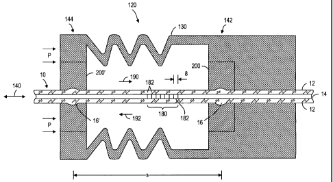
Referring to Fig. 2, a pressure sensor 120 comprises a single-mode optical
waveguide or optical fiber 10 having a core 14 and a cladding 12. The cladding
12
has a plurality of variation regions 16, 16' and a Bragg grating 180 imparted
in the
core 14 between the variation regions 16, 16'. A first attachment mechanism
200 is
disposed against the optical fiber 10 at a first mounting location 142, and a
second
attachment mechanism 200' is disposed against the optical fiber 10 at a second
mounting location 144. The attachment mechanisms 200, 200' are fixedly mounted
on
a pressure sensing device, such as a multi-element bellows structure 130 to
sense the
pressure P along the longitudinal axis 140 of the optical fiber 10. The Bragg
grating
180 has a plurality of "fringes" 182 formed from perturbations in the
refractive index
of the core 14. These perturbations are defined by spacing S for at least
partially
reflecting an optical signal 190 transmitted in the optical fiber 10. The
reflected
signal is denoted by reference numeral 192. Bragg gratings are well known. A
Bragg
grating is a periodic or aperiodic variation in the effective refractive index
and/or
effective optical absorption coeffieient of an optical waveguide, such as that
described
in US Patent No. 4,725,110 and 4,807,950, entitled "Method for Impressing
Gratings
Within Fiber Optics", to Glenn et al; and US Patent No. 5,388,173, entitled
"Method
and Apparatus for Forming Aperiodic Gratings in Optical Fibers", to Glenn.
The grating 180 may be in the core 14 and/or in the cladding 12. Any
9
CA 02449130 2003-12-01
WO 02/097388 PCT/GB02/02153
wavelength-tunable grating or reflective element embedded, etched, imprinted,
or
otherwise formed in the waveguide 10 may be used if desired. The waveguide 10
may
be photosensitive if a grating 180 is to be written into the waveguide 10. As
used
herein, the term "grating" means any of such reflective elements. Further, the
reflective element (or grating) 180 may be used in reflection and/or
transmission of
light. Light 140 incident on the grating 180 reflects a portion thereof having
a
predetermined wavelength band of light, and passes the remaining wavelengths
of the
incident light as is known. The Bragg grating 180, when used in the pressure
sensor
120, according to the present invention, is used to selectively reflect a
particular
frequency or wavelength of light that is propagated along the core 14. The
particular
wavelength of light reflected by the Bragg grating 180 is uniquely detennined
by the
grating spacing S as is known and is referred to as the Bragg, or reflection,
or
characteristic wavelength. A broadband, or a scanned narrow band, light source
is
used to provide the optical signal 190, or other types of sources may be used,
provided that the source has wavelengths that reflect off the desired gratings
in the
sensors. As shown in Fig.2, the distance between the first mounting location
142 and
the second mounting location 144 is denoted by S, which is subject to change
according to the pressure P. If the fiber 10 between locations 142, 144 is
held in
tension, when the distance S decreases, the tension (or tensile strain) on the
fiber 10
and the grating 180, decreases and the characteristic wavelength of the
grating
changes accordingly. It should be understood that the amount of distance
change may
be very small, e.g. picometers or nanometers. When a distributed pressure
sensing
system having a plurality of pressure sensors is used to measure pressure at a
plurality
of locations, the wavelength of the Bragg grating at each location may be
different
from the spacing for the Bragg grating at other locations. In this respect,
the
distributed pressure sensing system is effectively operated in a wavelength
division
multiplexing fashion. Pressure sensing using Bragg gratings at one or more
locations
is well known, as described in the aforementioned U.S. Patent No. 6,016,702
entitled
"High Sensitivity Fiber Optic Pressure Sensor for Use in Harsh Environments",
issued
to Robert J. Maron, referenced earlier. The main object of the present
invention is to
make pressure sensors more reliable by providing a method and system for
firmly
attaching the optical fiber 10 to a pressure sensitive structure so that the
changes in
the spacing S of the Bragg grating are accurately indicative of the changes in
the
CA 02449130 2003-12-01
WO 02/097388 PCT/GB02/02153
pressure P. In particular, according to the present invention, at each sensing
location,
two attachment mechanisms 200, 200' are attached to the optical fiber 10 at
two
mounting locations 142, 144. At each of the mounting locations, a variation
region
16, 16' of the cladding 14 is provided so that the attachment mechanism can be
firmly
disposed against the cladding 14. In general, the outside diameter of cladding
at the
variation region 16, 16' is different from the outside diameter of cladding in
other
parts of the optical fiber 10. The variation region can be an expanded region
or a
recessed region and have various shapes. The object is to prevent relative
movement
between the attachment mechanism and the optical fiber at the mounting
location.
Figs. 3 to 10 illustrate various embodiments of the attachment mechanism,
according
to the present invention.
Referring to Fig. 3, the cladding 12 of the optical fiber 10 has an outer
diameter dl of about 125 microns and the core 14 has a diameter d2 of
approximately
7-10 microns (e.g., 9 microns). The fiber 10 is designed to propagate light
along the
core 14 of the fiber 10. The cladding 12 and the core 14 are made of fused
silica glass
or doped silica glasses. Other materials for the optical fiber or waveguide
may be
used if desired. The fiber 10 has a region 16 with an expanded (or increased)
outer
diameter (or dimension). The expanded region 16 has a length L of about 500
microns, and an outer diameter d3 of about 200 microns. Other dimensions of
the
cladding 12, core 14, and expanded region 16 may be used if desired, provided
the
diameter d3 of the expanded region 16 is greater than the diameter dl. Also,
the fiber
10 may have an outer coating or buffer layer 18 used to protect the fiber
and/or
enhance attachment to the fiber (discussed more hereinafter).
The region 16 may be made by any technique for making a variation region in
an outer dimension of a waveguide. Some techniques for making the region 16
are
described in conjunction with Figs. 11-14 below. A device for creating an
expanded
region 16 is described in conjunction with Figs. 15 and 16. The region 16
allows the
fiber 10 to be attached to a structure in many different ways, as described
hereinafter
with Figs. 3-10.
In particular, referring to Fig. 3, a ferrule 30 (or sleeve) may be butted (or
mated) against at least a portion of the expanded region 16 to provide a
mechanical
stop (or lock), which substantially prevents the fiber 10 from moving to the
left
relative to the ferrule 30, as indicated by a line 20 (i.e., the direction of
an applied
11
CA 02449130 2003-12-01
WO 02/097388 PCT/GB02/02153
load on the fiber 10). The ferrule 30 may have a generally cylindrical and/or
conical
shape, or other shapes as discussed more hereinafter. The ferrule 30 may also
overlap
all or a portion of the expanded region 16. It is not required for the ferrule
30 to
overlap the expanded region 16; however, overlap reduces point contact
stresses on
the fiber/expanded region, to reduce the possibility of cracking the glass of
the fiber
and/or the expanded region 16, particularly when the expanded region 16 has a
curved geometry.
Referring again to Fig. 3, the ferrule 30 has a front region 32 with a
geometry
(shape, contour, or profile) that substantially corresponds to the geometry of
the
10 expanded region. The shape of the region 32 need not exactly match that of
the
expanded region 16, and may be a straight taper or bevel instead of a curved
surface.
Also, the ferrule 30 may have a beveled section 34 to provide some stress
relief on the
fiber when the fiber 10 flexes or is pulled off-axis from the ferrule 30.
Instead of the
taper 34, the ferrule 30 may be terminated with a sharp perpendicular edge, if
so
desired.
The ferrule 30 may be butted directly against the expanded region 16 or may
be bonded to the fiber 10 and/or the expanded region 16 with an adhesive
material
discussed hereinafter. The ferrule 30 may be pre-formed such that the shape of
the
front region 32 substantially conforms to the geometry of the expanded region
16.
However, if the shape of the ferrule 30 does not match that of the expanded
region 16,
a material, e.g., an adhesive, a coating and/or a filler (discussed more
hereinafter),
may be used to fill any gaps therebetween to reduce point contact stresses on
the
fiber/expanded region and/or to provide bonding therebetween.
Alternatively, the ferrule 30 may be heated andlor pressure (or force) applied
to the ferrule 30, e.g., by atmospheric (such as pressure and/or vacuum),
mechanical
(such as crimping), and/or magnetic techniques (such as electromagnetic
forming), or
any other technique, as indicated by arrows 42, to cause the ferrule 30 to
match at
least a portion of the geometry of the expanded region 16. For a glass
ferrule, the
ferrule 30 may be heated to a temperature at or below the softening
temperature of the
glass. For a metal ferrule, the ferrule may be heated to a temperature where
the metal
can be shaped. Alternatively, the ferrule 30 may be heated, held in place, and
the
fiber 10 pulled longitudinally toward and into contact with the ferrule 30 to
force the
ferrule 30 to conform to the shape of the variation region 16. This is
particularly
12
CA 02449130 2003-12-01
WO 02/097388 PCT/GB02/02153
useful when the ferrule 30 is made of a metal, which has a much lower
softening
temperature than the glass, but may be used for any ferrule material.
Alternatively, the ferrule 30 may have a section 38, which extends to the
right
of and overhangs the right side of the expanded region 16. In that case, the
region 40
between the inside of the ferrule 30 and the right side of the expanded region
16 may
be partially or completely filled with an adhesive, e.g., solder, braze,
epoxy, etc.,
similar to those discussed hereinafter. The adhesive may also fill any gaps on
the left
side of the region 16 along the region 32. In that case, to help minimize
creep, the
adhesive should be localized to the fiber variation region 16, and, thus,
avoiding
putting the adhesive in a region 33 will help avoid creep in the region 33.
Instead of
filling the region 40 with an adhesive, the section 38 may be heated and/or
pressure
(or force) applied to the section 38 (using any of the techniques discussed
hereinbefore with the arrows 42), as indicated by arrows 44, to force the
ferrule
section 38 to conform to at least a portion of the right side of the expanded
region 16.
Also, such heating and/or applying of pressure (or force) may be performed on
the
regions 32, 38 together, e.g., with a single crimping tool, coining tool, or
the like.
The ferrule 30 may be made of a ceramic/glass (e.g., sapphire, ruby, fused
quartz, fused silica, etc.), a metal (e.g., Invar (64%Fe, 36%Ni alloy), or
Kovar
(54%Fe, 29Ni, 17%Co)), or other low thermal expansion materials. The thermal
expansion coefficient of the ferrule 30 should be close to that of the optical
fiber 10 so
that the geometry of the ferrule 30 and the expanded region 16 and/or the
fiber 10 will
substantially track each other over temperature to minimize creep and point
contact
stresses. If the optical fiber comprises silica glass (and thus has a low
thermal
expansion), a low thermal expansion material is desirable for the ferrule 30.
Other
optical fiber or waveguide materials may be used if desired, with the material
for
ferrule 30 being selected to have a substantially similar thermal expansion
coefficient.
For any of the embodiments described herein, the ferrule 30 may be bonded to
the fiber 10 and/or expanded region 16 using epoxy, metal solders, metal
brazes, glass
solders, ceramic adhesives, or other adhesive materials depending on the
ferrule
material, the fiber material, and whether or not there is the outer buffer
layer (or
coating) 18 on the cladding 12 of the fiber 10. Alternatively, as discussed
hereinbefore, the ferrule may be butted-up against the region 16 without any
adhesives.
13
CA 02449130 2003-12-01
WO 02/097388 PCT/GB02/02153
Also, the buffer layer 18 (if used) may be made of various materials, e.g.,
metal, polymer, teflon, and/or cargon, or other materials, and may comprise a
plurality of layers. The buffer layer 18 may be used to protect the fiber,
and/or
enhance attachment of the ferrule 30 to the fiber (e.g., reduce creep). The
buffer layer
18 may comprise a metal layer (or metalized coating) made of a material that
is rigid
enough to protect the outer surface of the fiber to help prevent fiber
breakage at or
near the region 16. The metal layer may also be a material that is maleable
(i.e., a
material that deforms plastically under a compressive load) that can sustain
local
compressive loads and exhibits high plastic strain without material failure
(e.g.,
tearing, forming voids, etc.), which helps the ferrule 30 conform to the
geometry of
the region 16. Some such maleable metals include gold, platinum, nickel, etc.
Also,
the metal layer may be used to promote glass surface wetting for solders.
For example, the buffer layer 18 may be made of nickel-gold (NiAu), having a
thickness of about 1-3 microns Ni on the fiber and about 70-150 nanometers Au
on
the nickel, or thicker Au, e.g., about 1-10 microns, may be used. Such a
buffer layer
18 may be used with metal solder to solder the ferrule 30 to the layer 18, or
may be
used without any solder (where the ferrule is butted-up against the region
16). Other
metals and thickness may be used for the metal layer.
Alternatively, the buffer layer 18 may comprise a layer of polymer (e.g., high
temperature polyimide) having a thickness of about 1-10 microns over the metal
layer
or directly on the cladding 12 without the metal layer. Other types of
polymers and
thickness may be used. When a polymer is used, it may be necessary to heat the
combined fiber/variation/ferrule to an elevated temperature (e.g., at or above
the
operating temperature for the application) for a settling time, to allow the
polymer to
reach a steady state condition, e.g., thickness, shape, displacement, etc. and
thus
exhibit minimal creep. Other thicknesses, a number of layers, materials and
compositions of the layers of the buffer layer 18 may be used.
Also the ferrule 30 may have an inner diameter coating 41 of one or more of
the aforementioned maleable material(s), to help the ferrule 30 to conform to
the
geometry of the expanded region 16, thereby reducing point contact stresses on
the
fiber, and/or to enhance bonding to the buffer layer 18 or to the fiber 10.
Such an
inner coating on the ferrule 30 may be used whether or not the buffer layer 18
on the
fiber 10 is used, and whether or not the ferrule 30 is soldered to the fiber
10 or the
14
CA 02449130 2003-12-01
WO 02/097388 PCT/GB02/02153
expanded region 16. Also, the inner diameter of the ferrule 10 may be polished
to
reduce stress concentrations.
The ferrule 30 may be a one-piece ferrule, or a semi-circular two or more
piece ferrule. Using a multi-piece ferrule provides the advantage of not
having to
slide the ferrule 30 along the fiber 10 to the region 16, thereby reducing the
possibility
of scratching or causing other damage to the outer surface of the fiber 10
(with or
without the buffer coating 18) and allowing the buffer layer 18 away from the
region
16 to be thicker and/or non-uniform.
Referring to Fig. 4, in an alternative design of the ferrule 30, the section
38
extends to the right of and overhangs the right side of the expanded region 16
and
some of the fiber 10. If the ferrule 30 is a multi-piece ferrule, to hold such
a ferrule
together (around the fiber 10 and/or the region 16), the ferrule 30 may be
self-locking,
may be hinged (like a clamshell), and/or a collar 46 may be used. The collar
46 may
have a substantially straight inner diameter d5, of, e.g., 0.022 inches, which
substantially matches or is slightly less than the outer diameter of the
ferrule 30 to
provide a contacting or frictional fit between the collar 46 and the ferrule
30. Other
ferrule and collar diameters or dimensions may be used if desired. Also the
ferrule 30
may have an enlarged region 47 to provide a stop for the collar 46 or for
other
purposes. Further, the ferrule 30 may have a recessed region 48 to allow for
the collar
46 and ferrule 30 to mate flush at a face 45. Also, a slight bevel 49 may be
provided
on the collar 46 or the ferrule 30 to allow a tool, e.g., a razor blade, to be
inserted to
separate the collar 46 from the ferrule 30. The collar 46 may be made of the
same
material as the ferrule 30, or a material with substantially the same thermal
expansion
coefficient. Alternatively, the collar 46 may be made of heat shrinking
materials such
as metals, polymers, or shape memory alloys. To facilitate assembly of the
multi-
piece ferrule 30 onto the fiber 10, the multi-piece ferrule 30 may be placed
into the
collar 46 and then slid along the fiber 10 to the region 16. Then, heating
and/or
applying pressure (or force) to the collar 46 (such as discussed hereinbefore
with Fig.
3 with the ferrule 30) will cause at least a portion of the ferrule 30 to lock
onto at least
a portion of the region 16.
The length L2 of the ferrule 30 is about 0.075 inches. Other longer or shorter
lengths may be used for the ferrule 30.
CA 02449130 2003-12-01
WO 02/097388 PCT/GB02/02153
Referring to Fig. 5, instead of the ferrule 30 having a long cylindrical
shape, it
may be shorter and/or wider and may resemble a washer, bead or bearing jewel.
For
example, the ferrule 30 in Fig. 5 has an outer diameter d6 of about 0.033
inches and a
length L2 of about 0.031 inches with a tapered or beveled region 60 with a
taper angle
0 of about 13 degrees that extends beyond and overhangs at least a portion of
the
expanded region 16. The region 40 between the bottom side of the ferrule 30
and the
right side of the expanded region 16 (and a portion of the fiber 10) may
optionally be
partially or completely filled with an adhesive, e.g., solder, braze, epoxy,
etc., as
discussed hereinbefore. The adhesive may also fill any gaps on the left side
of the
region 16. Other diameters, lengths and taper angles may be used. Also, the
length of
the tapered region 60 may be shorter or there need not be any tapered region.
The
ferrule 30 may also be disposed within a housing 62, as discussed more
hereinafter.
Referring to Fig. 6, alternatively, the ferrule 30 may be placed (or
straddled)
across the expanded region 16. In that case, the ferrule 30 may have a
straight
(cylindrical) inside diameter which is larger than, or equal to the diameter
d3 of the
expanded region 16 plus the thickness of the coating 18 (if used). In that
case, regions
52 between the bottom side of the ferrule 30 and one or both sides of the
expanded
region 16 may be partially or completely filled with an adhesive, e.g.,
solder, braze,
epoxy, etc., similar to those discussed hereinbefore. Alternatively, the
ferrule 30 may
be heated and/or pressure (or force) applied, e.g., by atmospheric (such as
pressure
and/or vacuum), mechanical (such as crimping), and/or mechanical techniques,
or any
other techniques, across one or both sides of the expanded region 16 as
indicated by
arrows 54, which causes the ferrule 30 to conform to and be against at least a
portion
of the expanded region 16, as indicated by the dashed line profile 56.
The ferrule 30 may be much longer than that shown in Fig. 6 to the right (as
indicated by dashed lines 57) or to the left (as indicated by dashed lines 59)
or along
both sides, of the region 16, if desired. In that case, the ferrule 30 may be
locally
deformed to conform to one or both sides of the region 16. Also, if one or
both sides
of the ferrule 30 are made to conform to the region 16, one or more of the
aforementioned adhesives may also be used. Also, such heating and/or applying
of
pressure (or force) may be performed on the left and/or right sides of the
region 16
together, e.g., with a single crimping tool, coining tool, or the like.
16
CA 02449130 2003-12-01
WO 02/097388 PCT/GB02/02153
Referring to Fig. 7, in the event that the expanded region 16 has a straight
geometry, such as that shown by the lines 17, the ferrule 30 may be disposed
adjacent
to (or against) at least one of the vertical edges 17 of the expanded region
16. In that
case, the ferrule 30 may have a region 70 that overlaps all or a portion of
(or overhang
beyond) the top of the expanded region 16, and/or a region 72, that extends on
the
opposite side of the ferrule, which may have a tapered section 73, as
discussed
hereinbefore with Figs. 3 and 4. Also, a corner 74 of the ferrule 30 may be
rounded to
minimize damage to the outer surface of the fiber or coating 18 (if used), if
the ferrule
30 is slid along the fiber to the expanded region 16. Alternatively, instead
of having
the vertical edge 17 on both sides of the expanded region 16, the side of the
expanded
region 16 opposite from where the ferrule 30 contacts the edge 17 (e.g., the
right side)
may be rounded or another geometry, as indicated by the dashed lines 13.
Referring to Fig. 8, in the event that the expanded region 16 has a notch 11,
the ferrule 30 may have an inwardly protruding section (or tooth) 76, which
fits
within the notch 11 to lock the fiber 10 to the ferrule 30. Also, the ferrule
30 may be
a multi-piece ferrule (such as that discussed hereinbefore). In that case, to
hold the
ferrule 30 together, the ferrule 30 may be self-locking or there may be a
collar 78
around the ferrule 30. Also there may be a raised section 80 (at either end of
the
ferrule 30) to provide a stop for the collar 78 or for other purposes. The
notch 11
need not be centered along the expanded region 16, and the size of the tooth
76 need
not match the dimensions (e.g., length, depth) of the notch 11. Also, there
may be
more than one notch 11 and tooth 76. Further the length L2 of the ferrule 30
may
extend beyond the length L of the expanded region 16, but is not required to.
Referring to Fig. 9, alternatively, if the region 16 comprises a recess 8, the
tooth 76 of the ferrule 30 would be sized to substantially match at least a
portion of
the geometry of the recess 8. For example, if the geometry of the recess 8 is
curved,
as indicated by the dashed lines 9, the tooth 76 of the ferrule 30 would
likely also be
curved. If the geometry of the recess 8 has sharp edges 2, the tooth 76 may
likely
have at least one sharp edge to match at least one of the edges 2. Also the
length of
the tooth 76 may be shorter than the length of the recess 8. Further, the
length L2 of
the ferrule 30 may be longer than the length L of the recess 8. In that case,
there may
be one or more tapered surfaces 82, similar to that discussed hereinbefore, to
reduce
fiber stresses.
17
CA 02449130 2003-12-01
WO 02/097388 PCT/GB02/02153
Referring to Fig. 10, alternatively, if the region 16 has the recess 8, the
ferrule
30 may be a single or multi-piece cylindrical tube (or sleeve), which is
placed (or slid)
over the recess 8. In that case, a region 84 between the inside of the ferrule
30 and the
outside of the recess 8 may be partially or completely filled with an
adhesive, e.g.,
solder, braze, epoxy, etc., similar to those discussed hereinbefore. Instead
of using an
adhesive, the ferrule 30 may be heated and/or pressure applied across the
recess 8.,
e.g., by atmospheric (such as pressure and/or vacuum), mechanical (such as
crimping), and/or magnetic techniques (such as electro-magnetic forming), or
any
other technique, as indicated by arrows 90, which causes the ferrule 30 to
conform to
at least a portion of the shape of the recess 8, as indicated by the dashed
line profile
92. For a glass ferrule, the ferrule 30 may be heated to a temperature at or
below the
softening temperature of the glass. For a metal ferrule, the ferrule may be
heated to a
temperature where the metal can be shaped.
The ferrule 30 of any of the embodiments discussed herein may be connected
to or part of a structure (or housing), as discussed hereinbefore in the
Background Art
section hereto. Various techniques for attaching the ferrule 30 to the
structure may be
used, which depend on the application and the material of the ferrule 30.
For example, referring to Fig. 5, a housing 62 may surround at least a portion
of the ferrule 30 to hold the ferrule 30 in a predetermined position. The
housing 62
has a notch 64, which is substantially the same length or longer than the
length L2 of
the ferrule 30. The depth d7 of the notch 64 is deep enough to hold the
ferrule 30
from moving axially (in at least one direction). Also, the depth d7 may be
deep
enough to almost touch the fiber 10 (which may reduce non-axial motion of the
fiber
10). The shape of the housing 62 and the notch 64 may be cylindrical,
rectangular or
any other shape that allows the notch 64 to hold the ferrule 30. The housing
62 may
also be bonded to the ferrule 30 using an adhesive discussed hereinbefore
(e.g.,
solder, braze, epoxy, etc.). Also, the housing 62 may be anchored to the
ferrule 30 by
mechanical means, such as one or more set screws 66. Other techniques for
attaching
the ferrule 30 to the housing 62 may be used. The housing 62 may be used with
any
of the ferrules 30 discussed herein with suitable changes for the ferrule
geometry.
One technique for making the expanded region 16 in the optical fiber 10 is to
use a fiber (or fiber section), which has an enlarged diameter d4
substantially equal to
or greater than the diameter d3 of the region 16. The fiber section may be
made using
18
CA 02449130 2003-12-01
WO 02/097388 PCT/GB02/02153
a suitable glass pre-form with a cladding/core diameter ratio that can be
drawn down
using conventional techniques to achieve the desired core size but has a
cladding
outer diameter d4 which is greater than the desired value for the final
optical fiber.
To create the expanded region 16, as shown in Fig. 11, the diameter d4 of the
fiber 10
is reduced to the desired diameter by eliminating an outer portion 15 of the
cladding
by conventional (or yet to be developed) glass manufacturing techniques, e.g.,
grinding, etching, polishing, etc. If desired, some of the outer diameter of
the region
16 may also be removed. Using chemical etching (e.g., with hydrofluoric acid
or
other chemical etches), laser etching, or laser enhanced chemical etching are
some
techniques, which reduce the fiber's outer diameter without applying direct
contact
force, as is required by grinding and polishing. Certain types of etching may
produce
a sharper vertical edge 17 on the region 16, or an angled or curved edge 13.
Also,
selective etching may produce a notch 11 (or more than one notch) in the
region 16
(see Fig. 8). Also, the etching may produce the sharp edge 17 at one side
(e.g., the
left side) of the region 16 and the curved geometry 13 on the other side
(e.g., the right
side) of the region 16, as shown in Fig. 7.
Fire polishing using conventional techniques, i.e., applying heat for a
predetermined time across the region 16, may be performed after the etching to
smooth any rough surfaces that may be left by the etching process (as rough
surfaces
may increase stress levels and reduce fatigue life in dynamically loaded
fibers). The
fiber section may then be optically connected, e.g., by fusion splicing, by an
optical
connector, etc. to a standard-sized fiber (not shown) having a cladding and
core which
match the final fiber section described hereinbefore.
Referring to Fig. 12, alternatively, instead of the region 16 being made using
a
single axially continuous fiber, a fiber 4 having a length L and an outer
diameter dy
e.g., 125 microns, is fusion spliced between two fibers 3 having an outer
diameter dx,
e.g., 80 microns, at interfaces 5,6. The fibers 3,4 have the same core 14
diameter,
e.g., 9 microns, and may be fusion spliced using known splicing techniques.
Other
diameters for the claddings and cores of the fibers 3,4 may be used. The edge
17 may
be a vertical edge or may be a curved edge, as shown by the dashed lines 13.
Depending on the application, it may be desirable and/or acceptable to have
only one
change in the outer dimension of the fiber (or two changes located a long
distance
19
CA 02449130 2003-12-01
WO 02/097388 PCT/GB02/02153
apart). In that case, there would be one splice, e.g., at the interface 5,
between the
fibers 3,4 and the fiber 4 would be longer than that shown in Fig. 12.
Referring to Fig. 13, alternatively, a glass/ceramic tube (or sleeve) 7 may
surround the fiber 10 to create the expanded region 16. In that case, the tube
7 is
heated to the melting or softening temperature of the tube 7 such that the
tube 7 is
fused to or becomes part of the cladding 12. The tube 7 has a softening
temperature,
which is the same as or slightly lower than that of the fiber 10. Any form of
heating
may be used, e.g., oven, torch, laser filament, etc. The tube 7 may be a
single
cylindrical piece or have multiple pieces to surround the fiber 10. To help
keep the
tube concentric with the fiber, the process may be performed with the fiber
held
vertically. Also, more than one concentric tube may be used around the fiber
if
desired, each tube being melted onto an inner tube at the same time or
successively.
Referring to Fig. 14, alternatively, instead of the region 16 being an
expanded
outer dimension (or diameter), the region 16 may comprise a decreased outer
dimension (or recess or depression or notch) 8 in the waveguide 10. The recess
8 may
be created by numerous techniques, such as by reducing the outer diameter of
the
fiber 10 using the techniques discussed hereinbefore with Fig. 11 (e.g.,
grinding,
etching, polishing, etc.), by splicing a smaller diameter fiber between two
larger
diameter fibers, such as that discussed hereinbefore with Fig. 12, or by
heating and
stretching the desired region of the fiber by pulling on one or both ends of
the fiber 10
(i.e., putting the fiber 10 in tension) using a technique similar to that for
heating and
compressing the fiber to create a bulge in the fiber 10 (i.e., stretching
instead of
compressing), such as is described in conjunction with Fig. 15. Etching the
fiber 10
may created recessed vertical edges 2 (into the fiber 10) or a curved or
angled
recessed geometry 9, and heating and stretching the fiber 10 creates the
curved
geometry 9. The depth d8 of the recess 8 may be the same as the distance the
expanded region 16 in Figs. 3-5 extends from the cladding 12 diameter, e.g.,
about 75
microns. Other depths may be used.
If heating and stretching are used to create the recessed region 8, such a
process may be performed with the longitudinal axis of the fiber 10 aligned
horizontally or vertically or with other orientations. One advantage to
vertical
orientation is that it minimizes axial distortions caused by gravitational
effects of
CA 02449130 2003-12-01
WO 02/097388 PCT/GB02/02153
heating a fiber. Alternatively, the fiber may be rotated during heating and
stretching
to minimize gravity effects.
For any of the embodiments described herein, precise symmetry (axial or
cross-sectional) of the region 16 (for either expanded or recessed regions)
are not
required for the present invention. For example, the lower portion of the
regions 16,8
may be slightly larger or smaller than the upper portion, or vise versa.
However, the
core 14 should retain axial alignment along both sides of the region 16 (or 8)
to
minimize optical losses from the core 14 as light travels through the region
16. The
better the axial alignment of the core 14, the lower the optical loss.
Although the core
14 at the region 16 are shown as being straight, it should be understood that
there may
be some small amount of deformation of the core 14. The less deformation of
the
core 14 at the region 16, the lower the amount of optical loss. We have
measured
total optical losses as low as 0.06dB; however, lower losses may be achieved.
The
better the axial alignment of the core 14, the lower the optical loss.
Although the core
14 at the expanded region 16 is shown as being straight, it should be
understood that
there may be some small amount of deformation of the core 14. The less
deformation
of the core 14 at the bulge location, the lower the amount of optical loss.
Also, the
strength of the fiber 10 remains strong after the expanded region 16 is
created. For
example, we have measured a proof force of up to 4.66 lbs. of axial tension
force on
the fiber 10 before breakage occurs, which is comparable to a good fusion
splice.
Other fiber strengths may be obtained depending on the settings and method
used to
make the expanded region 16.
Also, for any of the embodiments described herein, instead of an optical fiber
10, any optical waveguide having a core and cladding may be used, e.g., a flat
or
planar waveguide, on which the region 16 can be created. In the case of a flat
or
planar waveguide, the region 16 may be on the upper and/or lower surfaces of
the
waveguide. Also, a multi-mode optical waveguide may be used if desired.
The region 16 may have other shapes (or geometries) than those described
herein, provided at least a portion of the optical waveguide has a variation
region,
deformation or change (expanded and/or recessed) of the outer dimension of the
waveguide.
Also, a combination of any of the above techniques for creating the region 16
may be used. For example, the etching technique discussed in conjunction with
Fig.
21
CA 02449130 2003-12-01
WO 02/097388 PCT/GB02/02153
11 may be used to alter the geometries described with Figs. 12-14. Other
techniques
than those described herein may be used if desired to create the region 16.
Also, the region 16 described with Figs. 11-14 may be combined to provide
both an expanded outer diameter region and a reduced diameter region. Further,
more
than one of the regions 16 may be provided along a given optical fiber if
desired.
After the regions 16 are made, the cladding 12 may be coated or re-coated
with a protective overcoat or buffer layer (see Fig. 3, for example), such as
a metal,
polymer, teflon, and/or carbon, or other materials, which may be used to
protect the
fiber and/or enhance attachment to the fiber.
Referring to Figs. 15 and 16, one technique for making the expanded region
16 in the optical fiber 10 is to heat and compress the fiber 10 as follows.
First, the
fiber 10 is prepared by stripping any protective over-coating or buffer layers
from the
fiber 10 to expose the cladding 12 of the fiber 10 in at least the area where
the
expanded region 16 is to be made. This may be done by chemical or thermal
techniques, such as dipping the desired section of the fiber in a hot bath of
sulfuric
acid. Then, the fiber is cleaned using well known procedures in the field of
optical
splicing, such as dipping in deionized water and then in isopropyl alcohol.
Other
stripping and/or cleaning techniques may be used if desired, providing they do
not
damage the fiber.
Referring to Figs. 15 and 16, a device 100 that may be used to make the
expanded region 16 is a Model FFS-1000 Filament Fusion Splicing System, made
by
Vytran Corp. The device 100 comprises a pair of movable fiber holding blocks
23, a
pair of vacuum V-groove fiber holders 22, a movable splice head 25 and a hinge-
mounted splice top 24 with a filament port hole 26. The fiber holding blocks
23
comprise a U-shaped frame and a center, spring-loaded block that contains a
vacuum
V-groove insert, in which the fiber is inserted. The components 22,23 are
aligned
such that the fiber 101ies substantially along a straight line. Within each of
the fiber
holding blocks 23, a stepper motor-driven worm-gear rotary mechanism (not
shown)
allows for movement of the blocks 23 (and thus the fiber 10) along the
longitudinal
axis of the fiber 10. The parts 22-26 are supported by a transfer jig or
housing 27.
The splice head 25 comprises a heat source, e.g., a resistive heating element
(such as a
Tungsten filament ribbon) 29 (Fig. 16) having a width W of about 0.025 inches,
which provides radiation heating evenly around the circumference of the fiber
10.
22
CA 02449130 2003-12-01
WO 02/097388 PCT/GB02/02153
Other heating techniques may be used if desired, e.g., a laser, a small oven,
a torch,
etc. Also, other devices and components for aligning and axially compressing
the
fiber 10 may be used, if so desired.
The fiber 10 is placed in the blocks 23 and the holders 22 (and across the
splice head 25), which places the longitudinal axis of the fiber 10
substantially along a
straight line, i.e., in axial alignment (along the longitudinal or Z-axis of
the fiber).
The vacuum in the vacuum V-groove fiber holders 22 is set strong enough to
keep the
fiber in axial alignment but not so strong as to cause surface defects on the
fiber.
Next, the fiber 10 is heated where the bulge is to be made by applying a
predetermined amount of power to the filament 29, e.g., about 26 Watts power.
The
heating element reaches a temperature (approximately 2100 C), such that the
glass is
at about 2000 C (the melting or softening temperature of the glass fiber). The
heat is
applied to the fiber for a duration (pre-heat time) long enough to soften the
fiber 10
enough to be compressed, e.g., approximately one second.
Then, while heat is still being applied to the fiber 10, the fiber 10 is
compressed axially by translation of the blocks 23 toward each other as
indicated by
the arrows 21 by the motors within the blocks 23. The total translation of the
blocks
23 (and thus compression of the fiber 10) is about 400 microns at a rate of
100
microns/sec for about 4 seconds. Other compression amounts, rates, and times
for the
axial compression may be used, if so desired. Compression may be achieved by
moving one or both blocks 23 provided the same total motion occurs. After the
compression is complete, the heating of the fiber may be maintained for a
predetermined post-compression time, approximately 0.25 seconds, to allow the
expanded region 16 to reach final form. Other pre-heat times and post-
compression
times may be used.
Next, the fiber 10 is again heated with the filament 29 (or "fire polished")
to
remove surface defects, at a power setting of about 21.5 Watts. During fire
polishing,
the filament (and the splice head 25) is moved back and forth (e.g., 2 full
passes)
across a predetermined length of the fiber (about 2500 microns) across where
the
expanded region 16 was formed, as indicated by the arrows 19, for a duration
of about
3 seconds. Other fire polishing power (temperature), number of passes, and
time
settings may be used, if so desired, provided the surface defects are removed
and the
expanded region 16 is substantially not altered or deformed. The fire
polishing may
23
CA 02449130 2003-12-01
WO 02/097388 PCT/GB02/02153
be performed immediately after forming the expanded region without stopping
the
heating of the fiber, or the heating of the fiber may be stopped (filament
turned off)
for a predetermined period of time after compression is complete and then
turned on
to perform the fire polish.
Also, during heating, the area within the splice head 25 around the fiber 10
is
purged with flowing high purity argon gas to keep the fiber clean and to
prevent high
temperature oxidation of the tungsten filament.
The parameter settings (times, powers, etc.) described above result in an
acceptable combination of mechanical strength and low optical loss. However,
other
suitable parameter combinations may be used, if desired, to obtain a similar
effect,
which may be determined by one skilled in the art in view of the teachings
herein.
The process described for making the expanded area 16 may be performed
with the longitudinal axis of the fiber 10 (and the device 100) aligned
horizontally or
vertically or with other orientations. One advantage to vertical orientation
is that it
minimizes axial distortions caused by gravitational effects of heating a
fiber.
Alternatively, the fiber may be rotated during heating and compression to
minimize
gravity effects.
After the expanded area 16 is made, the cladding 12 may be re-coated with the
protective overcoat or buffer layer 18 (see Fig. 3, for example), such as a
metal,
polymer, teflon, and/or carbon, or other materials.
The ferrule 30 may have other shapes, sizes, and/or designs than those
described herein, that has at least a portion of the ferrule 30 that
mechanically locks,
stops, or otherwise is disposed against at least a portion of the variation
region 16 (or
8), so as to minimize (or substantially prevent) relative movement (or creep)
in at
least one direction between the fiber 10 and the ferrule 30 (i.e.,
substantially prevents
the fiber 10 from moving in a predetermined direction relative to the ferrule
30 and
substantially prevents the ferrule 30 from moving in a direction opposite to
the
predetermined direction relative to the fiber 10), which causes the fiber 10
to
substantially track movement of the ferrule 30. Also, the ferrule 30 may be
placed
against the right side of the expanded region 16 instead of, or in addition
to, the left
side of the expanded region 16.
Also, instead of a ferrule 30, the region 16 may be placed in a housing or any
other structure having an internal shape that mechanically locks, stops, or
otherwise is
24
CA 02449130 2007-09-19
disposed against at least a portion of the variation region 16, which
minimizes relative
movement (or creep) in at least one direction between the fiber 10 and the
ferrule 30.
Also, although the fiber 10 and ferrule 30 are shown herein as being oriented
horizontally, the invention will work independent of the orientation of the
fiber 10 and
the ferrule 30, e.g., vertical, horizontal, or any other orientation.
In the detailed description taken in conjunction with Fig. t through Fig. 16,
the
emphasis has been placed on the pressure sensing technique using a Bragg
grating
imparted in an optical fiber fixedly mounted on two creep-resistant attachment
mechanisms. In particular, it has been described that the spacing of the Bragg
grating
is subject to change due to the pressure in an environment. It should be noted
that, in
addition to pressure, temperature also can cause changes in the effective
spacing S in
the Bragg grating 180 (Fig.2) in two different ways, as is known. One is due
to the
thermal expansion of the optical fiber and the mechanical attachments that
restrict the
movement of the optical fiber along the longitudinal axis thereof. The other
is the
optical pathlength change due to the change dn/dT of refractive index of the
fiber
core. Thus, the reflected signal 192 could also indicate changes in
temperature as
well as pressure. It is, however, possible to eliminate or compensate for the
temperature effect in the reflected signal 192. For example, a second grating
184 may
be placed in the fiber 10 outside the region so that it is not subject to
strains based on
pressure, but is in close thermal proximity to the grating 180 sensitive to
pressure. By
measuring the X shift from both gratings, the effect of temperature can be
eliminated.
(Also, see U.S. Patent 6,016,702 to Maron.) This type of "athennal" pressure
sensor
is also shown in Figs.18-20 discussed hereinafter. Alternatively, it is
possible to use a
slab of material having a certain coefficient of thermal expansion to cancel
out the
wavelength shift in the reflected signal, as described in U.S. Patent No.
6,621,957 entitled "Temperature Compensate Optical Device", which issued
Sept. 16, 2003.
Fig. 17 illustrates an optical signal processing system 350 for analyzing an
optical signal provided by one or more pressure sensors. As shown, a
distributed
pressure sensing system 352 comprises a plurality of pressure monitoring
sections
112a, I 12b,..., I 12n for measuring pressure at a plurality of locations in
an
environment. Each of the pressure monitoring sections has a pressure sensor
similar
to the pressure sensor, as shown in Figures 2, 18-21. As shown in Fig. 17, a
CA 02449130 2003-12-01
WO 02/097388 PCT/GB02/02153
broadband light source 310 is coupled to the optical fiber 10 via the coupler
312. The
coupler 312 directs light 190 to the distributed pressure sensing system 352.
The
reflected optical components 196 from the optical sensing system are directed
to an
optical signal processing unit 360. A filter system 364 is used to separate
the
response from different pressure monitoring sections 112a, 112b, ..., 112n.
The filter
system 364 separates the optical signals produced by each Bragg grating 180,
184 (see
Figure 19) by means of selective filtering. The wavelength shifts in the
optical
signals are analyzed by a wavelength shift monitoring device 366, such as that
described in US Patent No. 6,016,702, entitled "High Sensitivity Fiber Optic
Pressure
Sensor for Use in Harsh Environments", to Robert J. Maron, referenced earlier.
Fig. 18 is a side view cross-section of a housing 400 for implementing a
pressure sensor, according to the present invention, to measure pressure in a
harsh
environment, such as a wellbore, as shown in Figure 1. As shown, the housing
400
has a tubing 402 for providing an optical fiber 10 (Fig.20) and a mounting
mechanism
410 for mounting the tubing 402. The housing 400 also has an anchoring section
412
for mounting the mounting mechanism 410 and a multi-element bellows structure
420, allowing the multi-element bellows structure 420 to be compressed or
expanded
at the end 404. The housing is used to protect the components included therein
from
mechanical damage. Preferably, the housing 400 is made of a high strength,
rigid
wall, corrosion-resistant material, such as stainless steel. A section A of
the housing
is shown in detail in Fig. 19.
Referring to Fig. 19, an attachment mechanism 200 is mounted on one end of
the multi-element bellows structure 420 via a straight tube 422 and another
attachment mechanism 200' is mounted on the opposing end of the multi-element
bellows structure 420 via another straight tube 424. The grating 180 is
located in the
fiber 10 between the two attachment mechanisms 200, 200'. The straight tubes
422,
424 are secured to the bellows structure 420 with set screws 432 and 434. It
is
preferred that the straight tubes 422 and 424 are used to set the fiber 10 in
tension so
that when the housing is placed in a wellbore, the pressure in the wellbore
partially
relieves the tension in the fiber 10. A section B of the bellows structure 420
and the
mechanical components for mounting the fiber 10 is shown in Fig.20. As the
fiber 10
is pulled outward by the attachment mechanisms 200, 200', the straight tubes
422,
424 controls the separation between the attachment mechanisms 200, 200'. It is
26
CA 02449130 2007-09-19
possible to use a material for the tubes 424, 422 and the structure 420 having
a
coefficient of thermal expansion (CTE) so as to compensate for the wavelength
up-
shift of the fiber 10 due to the increase in the refractive index of the fiber
core with
regard to temperature.
It is known in the prior art to induce a compression force on an optical fiber
to
provide a broader range of sensing and/or tuning, as disclosed in U.S. Patent
5,469,520 to Morey. The present invention further includes an embodiment for
implementing a pressure sensor where the pressure places the fiber in
compression, as
shown in Figure 21. As shown in Figure 21, ferrules 500,502 are provided
within the
housing 420 between the gap between the straight tubes 422 and 424 to prevent
the
fiber 10 from buckling when a compression force in the direction of arrows
506, 508
is applied to the fiber 10. The housing 420 is coupled to any of the sensor
configurations described hereinabove, such as that shown in Figures 21, or any
other
sensor capable of transmitting a compression force on the fiber 10, in
response to a
positive pressure fluctuation. Pressure fluctuations produce a wavelength
shifl in the
Bragg grating 180, as described hereinabove, indicative of the pressure being
sensed.
The combination of the variation regions 16, 16' and the attachment mechanisms
200,200' of the present invention solves the attachment and creep problems of
the
prior art. The ferrules 500, 502 are substantially free to slide along the
housing 420.
In contrast, the fiber 10 is secured within the housing 420 by the variation
regions 16,
16' and the attachment mechanisms 200, 200' to prevent the fiber 10 from
sliding or
creeping during compression on the fiber 10 in the direction of arrows 506,
5Q8.
Preferably, a gap 504 is provided between the ferrule500 and 502 sufficient to
allow
compression of the fiber 10.
The grating may be used in transmission and/or reflection, as is known. When
two or more gratings are used for pressure sensing, the gratings may have the
same
reflection wavelengths and/or profiles or different wavelengths and/or
profiles. The
multiple gratings may be used individually in a known Fabry Perot arrangement.
Further, one or more fiber lasers, such as that described in US Patenl No.
5,513,913,
entitled "Active Multipoint Fiber Laser Sensor", US Patent No. 5,564, 832,
entitled
"Birefringent Active Fiber Laser Sensor", or US Patent No. 5,666,372,
"Compression
Tuned Fiber Laser", may be embedded within the fiber 10 for pressure sensing,
27
CA 02449130 2007-09-19
In that case, the gratings form an optical cavity and the fiber 10 at least
between the gratings (and may also include the gratings and/or the fiber 10
outside the
gratings, if desired) would be doped with a rare earth dopant, e.g. erbium
and/or
ytterbium, etc., and the lasing wavelength would shift as pressure changes.
Furthermore, another type of tunable fiber laser that may be used is a tunable
distributed feedback (DFB) fiber laser, such as that described in V.C.
Lauridsen, et al,
"Design of DFB Fibre Lasers", Electronic Letters, Oct. 15, 1998, Vol.34,
No.21,
pp2028-2030; P. Varming et al, "Erbium Doped Fiber DGB Laser With Permanent
7r/2 Phase-Shift Induced by UV Post-Processing", IOOC'95, Tech. Digest, Vol.5,
PDI-3, 1995; US Patent No. 5,771,251, "Optical Fibre Distributed Feedback
Laser",
to Kringlebotn et al; or US patent No. 5,511,083, "Polarized Fiber Laser
Source", to
D'Amato et al. In that case, the grating is written in a rare-earth doped
fiber and
configured to have a phase shift of a12 (where ). is the lasing wavelength) at
a
predetermined location near the center of the grating, which provides a well
defined
resonance condition that may be continuously tuned in single longitudinal mode
operation without mode hopping, as is known. Altematively, instead of a single
grating, the two gratings may be placed close enough to form a cavity having a
length
of (N +%z) k where N is an integer (including 0) and the gratings are in rare-
earth
doped fiber.
Altematively, the DFB laser may be located on the fiber 10 between the pair
of gratings 180 where the fiber 10 is doped with a rare-earth dopant along at
least a
portion of the distance between the gratings. Such configuration is referred
to as an
"interactive fiber laser", as set forth in U.S. Patent No. 5,699,377 to J. J.
Pan et al,
entitled "Narrow Linewidth, Stabilized Semiconductor Laser Source", E-tek
Dynamics, Inc., San Jose, CA. Other single or multiple fiber laser
configurations may be disposed on the fiber 10 if desired.
It should be understood that any of the features, characteristics,
alternatives or
modifications described regarding a particular embodiment herein may also be
applied, used, or incorporated with any other embodiment described herein.
Although the invention has been described and illustrated with respect to
exemplary embodiments thereof, the foregoing and various other additions and
28
CA 02449130 2003-12-01
WO 02/097388 PCT/GB02/02153
omissions may be made therein and thereto without departing from the spirit
and
scope of the present invention.
29