Note: Descriptions are shown in the official language in which they were submitted.
CA 02449370 2004-08-10
JAM RECOVERY METHOD FOR A CARD SHUFFLER
This is a divisional of Canadian patent application serial number 2,197,124,
which is the National
Phase application of International application number PCT/US95/09536 filed
July 28, 1995.
Technical Field
The present invention relates to devices for shuffling playing cards used
in playing games. In particular, it relates to an electromechanical machine
for
shuffling playing cards, wherein the machine is specifically adapted to
shuffle
multiple decks of playing cards to improve casino play of card games.
y0 Background of the Invention
Wagering games based on the outcome of randomly generated or selected
symbols are well known. Such games are widely played in gambling casinos and
include card games wherein the symbols comprise familiar, common playing
cards. Card games such as twenty-one or blackjack, Pai Gow poker, Caribbean
StudTM poker and others are excellent card games for use in casinos. Desirable
attributes of casino card games are that they are exciting, that they can be
learned
and understood easily by players, and that they move or are played rapidly to
their wager-resolving outcome.
One of the most popular of the above-mentioned casino games is twenty-
one. As outlined in U.S. Patent S,I54,492 (LeVasseur), conventional twenty-one
is played in most casinos and involves a game of chance between a dealer and
one or more players. The object is for the player to achieve a count of his
hand
closer to 21 than the count of the hand of the dealer. If the count of the
player's
hand goes over 21 then the player loses regardless of the final count of the
dealer's hand.
At least one standard deck of playing cards is used to play the game. Each
card counts its face value, except aces which have a value of one or eleven as
is
most beneficial to the count of the hand. Each player initially receives two
cards.
The dealer also receives two cards. One of the dealer's cards is dealt face
down
and the other of the dealer's cards is dealt face up.
A player may draw additional cards (take "hits") in order to try and beat
the count of the dealer's hand. If the player's count exceeds 21, the players
"busts." The player may "stand" on any count of 21 or less. When a player
busts,
he loses his wager regardless of whether or not the dealer busts. After all of
the
CA 02449370 2003-12-10
WO 96/04970 PCT/US95109536
2
players have taken hits or stood on their hand, the dealer "stands" or "hits"
based on pre-established rules for the game. Typically, if the dealer has less
than
17, the dealer must take a hit. If the dealer has 17 or more, the dealer
stands.
After the dealer's final hand has been established, the numerical count of
the dealer's hand is compared to the numerical count of the player's hand. If
the
dealer busts, the player wins regardless of the numerical count of his hand.
If
neither the player nor the dealer have busted, the closest hand to numerical
count of 21, without going over, wins; tie hands are a "push."
As used in the preceding description and in this disclosure, the terms
"conventional twenty-one" and "the conventional manner of play of twenty-
one" mean the game of twenty-one as described herein and also including any of
the known variations of the game of twenty-one.
Twenty-one has remained remarkably popular and unchanged over the
years. Because of its popularity, the rapidity of play, and the need to reduce
or
eliminate card counting by players, twenty-one is usually played with multiple
decks that are frequently shuffled. Thus, from the perspective of a casino,
the
play of a round of twenty-one takes a predictable length of time. In
particular,
the time the dealer must spend in shuffling diminishes the excitement of the
game and reduces the number of wagers placed and resolved in a given amount
of time. Modifications of the basic twenty-one game, including the LeVasseur
modification, have been proposed to speed play or otherwise increase the
number of wagers made and resolved, but none of these modifications have
achieved a large measure of popularity, probably because they change the game.
Casinos would like to increase the amount of revenue generated by the
game of twenty-one in the same time period without changing the game or
simply increasing the size of the wagers of the player. Therefor, another
approach to speeding play is directed specifically to the fact that playing
time is
diminished by shuffling and dealing. This problem is particularly acute in
games
such as twenty-one, but in other casino games as well, for which multiple
3o shuffled decks are used and has lead to the development of
electromechanical or
mechanical card shuffling devices. Such devices increase the speed of
shuffling
and dealing, thereby increasing playing time, adding to the excitement of a
game
by reducing the time the dealer or house has to spend in preparing to play the
game.
CA 02449370 2003-12-10
WO 96/04970 PCTlUS95/09536
3
U.S. Patents 4,513,969 (Samsel, Jr.) and 4,515,367 (f-ioward) disclose
automatic card shufflers. The Samsel, Jr. patent discloses a card shuffler
having a
housing with two wells for receiving two reserve stacks of cards. A first
extractor
selects, removes and intermixes the bottommost card from each stack and
delivers the intermixed cards to a storage compartment. A second extractor
sequentially removes the bottommost card from the storage compartment and
delivers it to a typical shoe from which the dealer may take it for
presentation to
the players. The Howard patent discloses a card mixer for randomly
interleaving
cards including a carriage supported ejector for ejecting a group of cards
(approximately two playing decks in number) which may then be removed
manually from the shuffler or dropped automatically into a chute for delivery
to
a typical dealing shoe.
U.S. Patent 4,5$6,712 (Lorber, et al.) discloses an automatic shuffling
apparatus designed to intermix cards under the programmed control of a
computer and is directed toward reducing the dead time generated when a casino
dealer manually has to shuffle multiple decks of playing cards. The Lorber, et
al.
apparatus is a carousel-type shuffler having a container, a storage device for
storing shuffled playing cards, a removing device and an inserting device for
intermixing the playing cards in the container, a dealing shoe and supplying
2o means for supplying the shuffled playing cards from the storage device to
the
dealing shoe.
U.S. Patent 5,000,453 (Stevens et al.) discloses an apparatus for
automatically shuffling and cutting cards. The Stevens et al. machine includes
three contiguous magazines with an elevatable platform card supporting means
in the center magazine only. Unshuffled cards are placed in the center
magazine
and the spitting rollers at the top of the magazine spit the cards randomly to
the
left and right magazine where they accumulate. This amounts to a
simultaneous cutting and shuffling step. The cards are moved back into the
center magazine by direct lateral movement of each shuffled stack, placing one
stack on top of the other to stack all cards in a shuffled stack in the center
magazine. The order of the cards in each stack does not change in moving from
the right and left magazines into the center magazine. The Stevens et al.
device
does not provide a distinct cutting step in the shuffling procedure. Cutting
is a
traditional step taken before shuffling cards and provides a sense of security
far
CA 02449370 2003-12-10
WO 96/04970 PCT/US95/09536
4
card players. In a further departure from "normal" manual or hand shuffling,
the Stevens et al. device shuffles cards by randomly diverging cards from an
unshuffled stack of cards. Normally, cards are cut and then randomly merged to
interleaf them into a single stack of shuffled cards.
Other known card shuffling devices are disclosed in U.S. Patents 2,778,644
(Stephenson), 4,497,488 (Plevyak et al.), 4,807,884 and 5,275,411 (the latter
two
patents issued to John G. Breeding, a co-inventor of the present invention,
and
commonly owned). The Breeding patents disclose machines for automatically
shuffling a single deck of cards including a deck receiving zone, a carriage
section
1o for separating a deck into two deck portions, a sloped mechanism positioned
between adjacent corners of the deck portions, and an apparatus for snapping
the
cards over the sloped mechanism to interleave the cards. They are directed to
providing a mechanized card shuffler whereby a deck may be shuffled often and
yet the dealer still has adequate time to operate the game being played.
Additionally, the Breeding shuffling devices are directed to reducing the
chance
that cards become marked as they are shuffled and to keeping the cards in view
constantly while they are being shuffled.
One reason why known shuffling machines, with the exception of the
Breeding machines, have failed to achieve widespread use is that they involve
or
use non-traditional manipulation of cards, making players wary and
uncomfortable. Although the devices disclosed in the preceding patents,
particularly the Breeding single deck card shuffling machines, provide
significant
improvements in card shuffling devices, such devices could be improved further
if they could automatically, effectively and randomly shuffle together
multiple
decks of playing cards in a shuffling operation which approximates as closely
as
possible the steps in manual or hand shuffling.
Accordingly, there is a need for a shuffling machine for shuffling playing
cards, wherein the machine is adapted to facilitate the casino play of card
games
wherein it is advantageous to have intermingled, multiple decks of cards
shuffled and ready for use.
Summary of the Invention
The problems outlined above are in large measure solved by the card
shuffling machine of the present invention, which provides for randorr~ly
CA 02449370 2003-12-10
shuffling together multiple decks of playing cards to facilitate the casino
play of certain
wagering games, particularly the game known as twenty-one or blackjack.
The present invention comprises an electromechanical card shuffling machine
for
shuffling intermingled multiple decks of playing cards, most typically four to
eight decks.
The shuffling procedure is controlled by an integral microprocessor and
monitored by a
plurality of photosensors and limit switches. The machine includes a first
vertically
extending magazine for holding a vertically registered stack of unshuffled
playing cards,
and second and third vertically extending magazines for holding a vertically
registered
stack of cards, the second and third magazines being horizontally spaced from
and
adjoining the first magazine. A first card mover is disposed at the top of the
first
magazine for individually engaging and moving cards from the top of the stack
of cards
in the first magazine horizontally and alternatively to the second and third
magazine to
cut the stack of unshuffled playing cards into two unshuffled stacks. Second
and third
card movers are at the top of the second and third magazines, respectively,
for randomly
moving individual cards from the top of the stacks of cards in the second and
third
magazines, respectively, to the first magazine, thereby interleaving the cards
to form a
vertically registered stack of shuffled cards in the first magazine.
An object of the present invention is to provide an electromechanical card
shuffling apparatus for automatically and randomly shuffling multiple decks of
playing
cards.
Another object of the present invention is to provide an electromechanical
card
shuffling device for shuffling cards, thereby facilitating and improving the
casino playing
of wagering games, particularly twenty-one.
Additional objects of the presenting invention are to reduce dealer shuffling
time,
thereby increasing the playing time, and to reduce or eliminate problems such
as card
counting, possible dealer manipulation and card tracking, thereby increasing
the integrity
of a game and enhancing casino security.
Another object of the present invention is to improve the art of card
shuffling by providing a card shuffling machine for randomly shuffling
together
multiple decks of cards, just as the devices disclosed in U.S. Patents
4,807,884 and
5,275,41 l, provide for the automatic, random shuffling of a single deck of
playing cards.
CA 02449370 2003-12-10
6
A feature of the machine of the present invention is a transparent,
machine operated access door for the card shuffling chamber of the machine. An
associated advantage is that all the cards are completely visible to players
all
during the shuffling process.
The present invention includes automatic jammed shuffle detection and
rectification features and procedures which are operated and controlled by the
microprocessor. Another feature of the present invention is an integral
exhaust
fan or blower system for keeping the interior surfaces of the machine,
including
slide surfaces and the photosensors free of dust and cool.
Additional advantages of the shuffling machine of the present invention
are that it facilitates and speeds the play of casino wagering games,
particularly
twenty-one, making the games more exciting for players. It also reduces the
effectiveness of card counting or tracking by players by enabling the
shuffling of
and play from multiple decks of cards.
i5 In use, the machine of the present invention is operated. to repeatedly
shuffle up to eight decks of playing cards. The access door is opened, and the
dealer places the selected number of unshuffled decks in the first, central
magazine. The machine is started and, under the control of the integral
microprocessor, the machine separates or cuts the unshuffled decks into two
unshuffled stacks, one in each of the second and third magazines. The machine
then randomly moves individual cards from the top of the stacks in the second
and third magazines back to the first magazine, interleaving the cards to form
a
vertically registered stack of shuffled Bards in the first magazine. The
machine
automatically repeats the shuffling sequence a preprogr ammed number of times
depending on the number of decks being shuffled.
CA 02449370 2003-12-10
6a
Accordingly, in one aspect, the present invention provides an apparatus for
shuffling playing cards comprising: a card-moving mechanism; a processing unit
that
controls the card-moving mechanism so that cards are moved in a shuffling
cycle to and
from groups of cards including one or more groups of cut cards and a group of
shuffled
cards; a data storage medium accessible by the processing unit, wherein the
data
storage medium has a program stored on it, and wherein the program is
configured to
cause the processing unit to cause the card-moving mechanism to randomly move
cards
into the group of shuffled cards; and a counter for registering the use of the
apparatus.
In a further aspect, the present invention provides an apparatus for shuffling
playing cards which comprises: (a) f rst vertically extending magazine for
holding a
vertically registered stack of unshuffled playing cards, (h) second and third
vertically
extending magazines for holding a vertically registered stack of cards, each
horizontally
spaced from and adjoining the first magazine, (c) first card-engaging means
disposed at
the top of the first magazine for individually moving cards from the top of
the stack of
cards in the first magazine horizontally to the second and third magazine to
thereby cut
the stack of unshuffled playing cards into two stacks, (d) second and third
card-
engaging means disposed at the top of the second and third magazines,
respectively, for
simultaneously and randomly moving individual cards from the top of the stack
of
cards in the second and third magazines, respectively, to the first magazine,
to thereby
interleave the cards to form a vertically registered stack of shuffled cards
in the first
magazine, and (e) a counter for registering the amount of use of the
apparatus.
In a further aspect, the present invention provides a recovery method for
recovering from a card jam in an apparatus for automatically shuffling cards,
the
apparatus including a card mover for moving the cards and sensors for
monitoring
movement of the cards wherein, during normal movement, the cards are moved
substantially one at a time and the sensors are alternately blocked and
unblocked, said
recovery method comprising the steps of sensing a prolonged blocked state
thereby
indicating that the card jam has occurred; altering the normal movement of the
cards;
sensing an end of the prolonged blocked state; and resuming the normal
movement of
the cards.
CA 02449370 2003-12-10
6b
In a still further aspect, the present invention provides a recovery method
for
recovering from a card jam in an apparatus for automatically shuffling cards,
the
apparatus including sensors for monitoring movement of the cards wherein,
during
normal movement, the sensors are alternately blocked and unblocked, said
recovery
method including the steps of sensing a prolonged blocked state thereby
indicating
that the card jam has occurred; selectively altering the movement of the
cards;
sensing an end of the prolonged blocked state; and resuming the normal
movement
of the cards.
In a further aspect, the present invention provides an automatic card shuffler
comprising: a card moving mechanism; a mufti-segment display device; and a
controller for controlling operation of the shuffler, wherein the controller
is in
communication with the mufti-segment display device, wherein the shuffler
displays on the mufti-segment display shuffler state information.
In a still further aspect, the present invention provides a card shuffler
comprising: a card moving mechanism; a microprocessor for controlling
operation
of the card shuffler, including the card moving mechanism; memory; a program
stored in memory for controlling the card moving mechanism; at least one
detector
for detecting the presence of a card that is jammed; and a mufti-segment
display for
displaying the occurrence of a card jam.
In a further aspect, the present invention provides a recovery method for
recovering from a card jam in an apparatus for automatically shuffling cards,
the
apparatus including sensors for monitoring movement of the cards wherein,
during
normal movement, the sensors are alternatively blocked and unblocked, said
recovery method comprising the steps of: sensing a prolonged blocked state
thereby
indicating that the card jam has occurred; selectively altering the movement
of the
cards; sensing an end of the prolonged blocked state; and resuming the normal
movement of the cards wherein the apparatus includes card engaging means
operable to reverse the normal movement of the cards.
CA 02449370 2004-08-10
6c
In a still further aspect, the present invention provides a method of
recovering from a card jam in an automatic card shuffler, comprising:
providing an
automatic card shuffler with a microprocessor for controlling the operation of
the
card shuffler; manually removing cards upon the occurrence of a card jam,
wherein
after the jam is cleared, the microprocessor causes the shuffler to advance
through a
complete shuffle cycle after a jam is cleared.
In yet another aspect, the present invention provides a method of recovering
from a card jam in an automatic card shuffler, comprising: providing an
automatic
card shuffler with a microprocessor for controlling the operation of the card
shuffler; monitoring movement of cards within the card shuffler during
shuffling;
upon detecting a card jam in the card shuffler during shuffling by said
monitoring,
altering movement of cards within the card shuffler; and if the altering
movement
of cards is not indicated as having cleared the card jam, a visual indication
is
provided to an operator that cards should be manually removed, wherein after
the
jam is cleared by manual removal of cards, the microprocessor causes the
shuffler
to advance through a complete shuffle cycle after the jam is cleared.
Other objects, features and advantages of the present invention will become
more fully apparent and understood with reference to the following
specification
and to the appended drawings and claims.
Brief Description of the Drawings
Fig. 1 is a front perspective view depicting the present invention as it might
be disposed in a casino adjacent to a gaming table.
Fig. 2 is a fragmentary perspective view showing the invention from the
opposite side of that depicted Fig. 1.
CA 02449370 2003-12-10
WO 96J0~970 PCT/US95/09536
7
Fig. 3 is a rear elevational view of the shuffling machine of the present
invention with the exterior shroud removed.
Fig. 4 is a front elevational view of the present invention with the lower
front exterior shroud and the clear plastic door of the shuffling chamber
removed.
Fig. 4a is a front elevational view of the present invention with portions
broken away for clarity and with the drive motors shown in phantom.
Fig. 5 is a top plan view taken along line 5-5 in Fig. 4.
Fig. 6 is a sectional plan view taken along line 6-6 in Fig. 4.
Fig. 7 is a sectional elevation view taken along line T-7 in Fig. 4.
Fig. 8 is a sectional elevation view taken along line 8-8 in Fig. 4.
Fig. 9 is a sectional elevation view taken along line 9-9 in Fig. 8.
Fig. IO is a sectional elevation view taken along line IO-IO in Fig. 4.
Fig. 11 is a sectional elevation view taken along line 11-lI in Fig. 5.
Fig. 12 is a schematic diagram of the electrical control system.
Fig. I3 is a schematic diagram of the electrical control system.
Fig. 14 is a schematic diagram of the electrical control system with an
optically-isolated bus.
Fig. I5 is a detailed schematic diagram of a portion of Figure 14.
Fig. 16 is an exploded perspective assembly view of the shuffling machine
of the present invention showing all of the major component parts or sub-
assemblies of the machine.
Fig. 17 is a partially exploded perspective view depicting the assembly of
portions of the shuffling machine of the present invention.
Fig. 18 is an exploded perspective view depicting the transport assembly
exclusive of the transport rollers at the top of the shuffling machine, and
specifically shows the shuffling chamber.
Fig. 19 shows a series of stages that illustrate the movement of cards in one
embodiment of the present invention.
Fig. 20 is a flow diagram depicting the sequence of operations carried out
by the electrical control system of the present invention.
Detailed Description of the Preferred Embodiment
CA 02449370 2003-12-10
g
This detailed description is intended to be read and understood in conjunction
with
Appendices A, B, C and D, appended to the end hereof. Appendix A provides an
identification key correlating the description and abbreviation of certain
motors, switches
and photoeyes or sensors with reference character identifications of the same
components
in the Figures. Appendix B sets forth steps in the sequence of operations of
the shuffling
machine in accordance with the present invention. Appendix C describes the
homing
sequence, broadly part of the sequence of operations, and Appendix D sets
forth the
manufactures, addresses and model designations of certain components (motors,
limit
switches and photoeyes) of the present invention.
With regard to means for fastening, mounting, attaching or connecting the
components of the present invention to form the shuffling apparatus as a
whole, unless
specifically described as otherwise, such means are intended to encompass
conventional
fasteners such as machine screws, rivets, nuts and bolts, toggles, pins or the
like. Other
fastening or attachment means appropriate for connecting components include
adhesives,
welding and soldering, the latter particularly with regard to the electrical
system.
All components of the electrical system and wiring harness of the present
invention are conventional, commercially available components unless otherwise
indicated. This is intended to include electrical components and circuitry,
wires, fuses,
soldered connections, circuit boards and control system components.
Generally, unless specifically otherwise disclosed or taught, the materials
from
which the various components of the present invention, for example the shroud
and the
plates for forming the frame for supporting the shroud and other components,
are selected
from appropriate materials such as aluminum, steel, metallic alloys, various
plastics,
fibreglass or the like. Despite the foregoing indication that components and
materials for
use in and for forming or fabricating the shuffling machine of the present
invention may
be selected from commercially available, appropriate items, the Appendices and
the
following detailed description set forth specific items and steps for using
the present
invention, although it is possible that those skilled in the state of the art
will be able to
recognize and select equivalent items.
CA 02449370 2003-12-10
WO 96/04970 PCTIUS95109536
9
In the following description, the Appendices and the claims any references
to the terms right and left, top and bottom, upper and lower and horizontal
and
vertical are to be read and understood with their conventional meanings and
with reference to viewing the shuffling apparatus from the front as shown in
Figs. 4 and 4a and from the player's perspective as the apparatus is disposed
in
Fig. 1, which is a front perspective view of the machine 20 as it might be
disposed
in use at a typical casino gaming table T.
Referring then to the drawings, particularly Figs. I, 2 and 16, the shuffling
machine 20 for shuffling together multiple decks of playing cards in
accordance
with the present invention has an exterior shroud 24 including a rear cover 26
with vents 27, lower front cover 28 with vents 29 and top portion 30. The
cover
portions forming the shroud 24 are suitably mounted on a supporting
framework comprising a flat, generally horizontal base 32 carrying four non-
slip
feet 33 on its underside and a vertically oriented and extending main base
plate
34 fixedly and generally perpendicularly attached to the base 32 and supported
by
a pair of support brackets 36.
Together the shroud 24 and the framework define the three broad
operating chambers of the machine 20: a rear drive and control chamber 38, a
lower, front door and elevator transmission chamber 40, and a card-receiving
shuffling chamber 42.
With continued reference to Fig. 16, and to Figs. 3 and 4a, the rear chamber
38 houses the control system 46 for controlling and operating the machine 20
and
a plurality of stepper motors, as set forth in Appendix D. The motors include
a
left elevator motor 48, a center elevator motor 50 and a right elevator motor
52.
A second set or bank of stepper motors is attached to the main base plate 34
and
includes a left feed motor 54, a center feed motor 56 and a right feed motor
58. A
left speed-up stepper motor 60 and a right speed-up motor 62 are also mounted
on the main base plate 34. A door operating stepper motor 64, shown in
phantom in Fig. 3, is attached to the front of the main base plate 34 in the
lower
front chamber 40.
Referring to Figs. 4, 4a and 17, in the lower front chamber 40 the main base
plate 34 carries a plurality of limit switches, including a left elevator
bottom limit
switch 68, a center elevator bottom limit switch 72 and a right elevator
bottom
limit switch 76. At the top of the shuffling chamber 42, a transport assembly,
CA 02449370 2003-12-10
WO 96104970 PCTIUS95109536
indicated generally at 67, carries corresponding elevator limit switches
including
a left elevator top limit switch 70, a center elevator top limit switch 74 and
a right
elevator top limit switch 78. Door bottom and door top Iimit switches, 80, 82,
respectively, are mounted in the lower front chamber 40.
5 Referring to Figs. 4, 4a, b and 17, a horizontal central, generally flat
floor
plate assembly 86 separates the lower front chamber 40 from the shuffling
chamber 42, defining the bottom floor of the shuffling chamber 42. The floor
plate assembly 86 carries a left elevator empty photoeye 88 (the term photoeye
is
intended to be synonymous with photosensor and optical sensor), a center
1o elevator empty photoeye 90 and a right elevator empty photoeye 92. The
floor
plate assembly 86 also carries three fans, a left magazine fan 94, a center
magazine
fan 96 and a right magazine fan 98, each including a motor I00 and concentric
blades 102.
With reference to Figs. 4, 4a, 5 and 17, the top of the shuffling chamber 42
includes the transport assembly 67. The outer sides of the chamber 42 are
formed
by a pair of parallel side plates 112, 1I4. Adjacent to their upper inside
edge, each
plate 112, 113 carries at least one card stopping groove 115 (see Fig. 8).
Preferably
three parallel grooves are provided. The grooves help ensure that cards come
to
rest horizontally and face-down in the chamber 42. The chamber 42 is divided
into three adjoining, vertically extending card magazines, a left magazine
116, a
center magazine I18 and a right magazine 120 by two substantially similar left
and right center magazine plate assemblies 122, I24, respectively. Adjacent to
the
upper edges of the sides of the plate assemblies 122, 124, on the side facing
into
the center magazine 118 are card stopping grooves I23. The left plate assembly
I22 carries a left outer counter photoeye 128 and a left inner counter
photoeye
130. Similarly, the right plate assembly 124 carries a right outer counter
photoeye
132 and a right inner counter photoeye 134. With continuing reference to Fig.
17,
and to Figs. 8-10, each of the left and right center plate assemblies 122, 124
carries
a floating pinch roller assembly I40, 142 centered on its top edge. Both
roller
assemblies 140, 142 are substantially identical so only the right roller
assembly 142
will be described. The assembly 142 includes a non-driven or idler pinch
roller
146 supported on a shaft 148 and by a set of typical roller bearings 150. As
shown
in Fig. 9, the roller 146, shaft 148 and bearing 150 assembly is received in
and
supported by a spring block I52, in turn mounted on a pair of linear pinch
roller
CA 02449370 2003-12-10
WO 96/04970 PCTIUS95109536
11
shafts I54, each concentrically within a coil springs 156. This assembly is
received
by bushings 160 in the upper region of the plate assembly I42. The spring
block
I52 also carries a pair of card guides 162 with uppermost rounded shoulders
164,
each being fixedly attached adjacent to the ends of the spring block 152.
Along
the forward facing edge of the plate assemblies 122, 124, a wire housing
channel
170 (see Fig. 9), covered by a wire cover 172, is provided to receive a wire
(not
shown) which operably couples the card gap counting optical sensors or
photoeyes 128, 130, 132, 134 to the control system 46.
Referring to Figs. 3, 4, 5, 7, 8 and 11, as well the assembly drawing Fig. 17,
to the transport assembly 67 is mounted at the top of the side plates II2, I14
and
effectively closes or defines the upper region of the shuffling chamber 42.
The
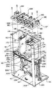
transport assembly 67 comprises a bearing plate 180 and three card moving
pickoff assemblies including a center pickoff assembly 182, a left side
pickoff
assembly 184 and a right side pickoff assembly 186. As shown in Fig. 5, the
pickoff assemblies are generally centrally positioned above the open top of
each
respective magazine. The center pickoff assembly 182, including a pickoff
roller
I90 carrying at least two sticky pickoff fingers or tabs 191 one hundred-
eighty
degrees apart, is connected to a center driven pulley 194 and, (referring to
Fig. 3)
via a belt I96, to the center feed motor 56. The shaft I92 extends through a
center
pickoff rocker block 198 pivotally mounted on the bearing plate 180, and its
ends
rest in an open-topped channel 199 in the bearing plate 180 (see Fig. 5).
Similarly, each of the left and right pickoff assemblies 184, 186 include a
pickoff roller 200, 202, respectively, carrying pickoff tabs 191. The rollers
200, 202
are mounted on shafts 204, 206, respectively connected to driven pulleys 208,
2I0
and, via belts 2I2, 214, to the left and right feed motors 54, 58. The shafts
204, 206
extend through rocker blocks 220, 222 which are pivotally mounted on the fixed
shafts 224, 226 of the speed-up assemblies 228, 230.
Each speed-up assembly 228, 230 includes a driven, floating speed-up roller
232, 234, respectively, fixed on a shaft 224, 226. Each roller 232, 234 is
above and
3o aligned with the rollers 146 of the pinch roller assemblies 140, 142. The
shafts
224, 226 are coupled to speed-up pulleys 236, 238, in turn coupled to the
speed-up
motors 60, 62 via belts 240, 242.
Referring to Figs. 4, 4a, 5, 11 and 17, the transport assembly 67 includes a
plurality of leaf-spring card deflectors 248 fixedly mounted on spring blocks
250.
CA 02449370 2003-12-10
WO 96104970 PCTlUS95109536
12
The deflectors 248 are generally over the speed-up assemblies 228, 230 and the
arms 249 of the defectors extend generally downwardly into the magazines I16,
I1$, I20 to contact cards moving in the cutting and shuffling movements
described below, thereby directing cards into proper position in the magazines
and helping to avert jams in the shuffling process. It should be understood
that
block-type deflectors (not shown) with appropriately curved or angled surfaces
could be mounted on the transport assembly 67 and substitute for or be used in
conjunction with the spring deflectors 248 depicted.
Referring to Figs. 4, 4a, 7, 16, 17 and 18, each magazine 116,118, 120
to contains a vertically movable elevator 260, 262, 264, respectively. The
elevators
260, 262, 264 are substantially similar comprising a vertically disposed
platform
mount 270 and a generally horizontal platform 272. The platform mount 270 for
each elevator 260, 262, 264 is mounted on a pair of vertically spaced mounting
brackets 304, in turn slidably received on elevator track 305. The track 305
is fixed
to base plate 34 in track receiving grooves 307 (see Fig. I8). The platforms
272 of
the elevators 260, 264 are substantially identical, each having a generally U-
shaped relieved area 276 on its forward facing leading edge, but the U-shaped
area on the leading edge of the platform of the center elevator 262 extends.
more
deeply rearwardly into the platform 272. Each platform 272 carries a belt
clamp
2o assembly 280 beneath and adjacent to its lower edge. The belt clamp
assembly 280
(best seen in Fig. 4) is clamped to elevator belts 282, a.s best seen in Figs.
7 and 4.
The belts 282 extend around idler pulleys 284 mounted on the main base plate
34.
The belts 282 are coupled to drive pulleys 286, in turn and respectively
connected
to the elevator motors 48, 50, 52 (Fig. 3).
With reference to Figs. 16, 17, 18 and 4, the lower front chamber 40 houses
an operating mechanism for the transparent front shuffling chamber door 290,
including the motor 64 operably linked via belt 292 to a door pulley 294 keyed
to
a door shaft 296 supported by a pair of door shaft bearing blocks 298. The
bearing
blocks 298 support or contain a set of conventional roller bearings (not
shown).
3o Referring to Figs. 16 and 17, each end of the door shaft 296 carries a
pinion wheel
302. The sides of the door 29 are provided with a plurality of in-line holes
to
receive the pinions, 302, respectively, and a pair of door blocks 306 is
connected to
the T-shaped columns 308 of the framework of the machine 20 to support and
guide the door 290 as it travels up and down.
CA 02449370 2003-12-10
WO 9b/04970 PCTILJS95I09536
13
Referring to Figs. I, 2 and machine assembly Fig. 16, controls 320 for
operating the shuffling machine 20 are mounted between the transport assembly
67 and the top portion 30 of the shroud 24. The controls 320 include an alarm
light 322, an open door command button 324, a reset command button 326 and a
start button 328.
Fig. I2 shows a block diagram depicting the electrical control system in one
embodiment of the present invention. The control system includes a controller
360, a bus 362, and a motor controller 364. Also represented in Fig. I2 are
inputs
366, outputs 368, and a motor system 370. The controller 360 sends signals to
both the motor controller 364 and the outputs 368 ~nrhile monitoring the
inputs
366. The motor controller 364 interprets signals received over the bus 362
from
the controller 360. The motor system 370 is driven by the motor controller 364
in
response to the commands from the controller 360. The controller 360 controls
the state of the outputs 368 by sending appropriate signals over the bus 362.
In the preferred embodiment of the present invention, the motor system
370 comprises nine motors that are used for operating the multi-deck shuffler
20.
Three elevator motors 48, 50, 52 drive the left, center, and right elevators
260, 262,
264; three feed motors 54, 56, 58 drive the left, centex, and right feed
rollers 200,
190, 202; and two motors 60, 62 drive the left and right speed-up rollers 232,
234.
A ninth motor 64 is used to open and close the door. In such an embodiment,
the motor controller 364 would normally comprise one or two controllers and
driver devices for each of the nine motors described above. However, other
configurations are obviously possible.
The outputs 368 include the alarm, start, and reset indicators described
above and may also include signals that can be used to drive a display device
(e.g., a seven segment display - not shown). Such a display device can be used
to
implement a timer, a card counter, or a shuffle cou.nte-. Generally, an
appropriate display device can be used to display any information worthy of
display.
The inputs 366 are signals from the Iimit switches, photoeyes, and buttons
described herein. The controller 360 receives the inputs 366 over the bus 362.
Although the controller 360 can be any digital controller or
microprocessor-based system, in the preferred embodiment, the controller 360
comprises a processing unit 380 and a peripheral device 382 as shown in Fig.
13.
CA 02449370 2003-12-10
WO 96104970 PCT/US95I09536
14
The processing unit 380 in the preferred embodiment is an 8-bit single-chip
microcomputer such as an 80C52 manufactured by the Intel Corporation of Santa
Clara, California. The peripheral device 382 is a field programmable
microcontroller peripheral device that includes programmable logic devices,
EPROMs, and input-output ports. As shown in Fig. 13, peripheral device 382
interfaces the processing unit 380 to the bus 362.
The series of instructions stored in the controller 360 is shown in Fig. 13 as
program logic 384. In the preferred embodiment, the program logic 384 is RAM
or ROM hardware in the peripheral device 382. (Since the processing unit 380
may have some memory capacity, it is possible that some of the instructions
are
stored in the processing unit 380.) As one skilled in the art will recognize,
various implementations of the program logic 384 are possible. The program
logic 384 could be either hardware, software, or a combination of both.
Hardware
implementations might involve hardwired controller logic or instructions
stored in a ROM or RAM device. Software implementations would involve
instructions stored on a magnetic, optical, or other media that can be
accessed by
the processing unit 380.
It is possible in some environments for a significant amount of
electrostatic energy to build up in the shuffling machine 20. Significant
2d electrostatic discharge can affect the operation of the machine 20 and
perhaps
even cause a hazard to those near the machine 20. It is therefore helpful to
isolate some of the circuitry of the control system from the rest of the
machine.
In the preferred embodiment of the present invention, a number of optically-
coupled isolators are used to act as a barrier to electrostatic discharge.
As shown in Fig. 14, a first group of circuitry 390 can be electrically
isolated
from a second group of circuitry 392 by using optically-coupled logic gates
that
have light-emitting diodes to optically (rather than electrically) transmit a
digital
signal, and photodetectors to receive the optically-transmitted data. An
illustration of the electrical isolation through the use of optically-coupled
logic
gages is shown in Fig. 15, which shows a portion of Fig. 14 in detail. Four
Hewlett Packard HCPL-2630 optocouplers (labeled 394, 396, 398, and 400) are
used
to provide an 8-bit isolated data path to the output devices 368. Each bit of
data is
represented by both an LED 402 and a photodetector 404. The LEDs emit light
CA 02449370 2003-12-10
WO 96/04970 PCT/IJS95109536
when forward biased, and the photodetectors detect the presence or absence of
the light. Data is thus transmitted without an electrical connection.
Figs. I and 2 depict a typical installation of the machine 20 of the present
invention. Typically the machine 20 will be supported on a pedestal type
table, t,
5 located immediately adjacent to and behind a typical gaming table, T. The
shroud 24 includes an adapting flange 330. The flange 330 helps connect the
machine 20 to the gambling table, T, to reduce the chance that a dealer
standing
generally centrally behind the table T with the machine 20 on his left will
drop
cards between the table and the apparatus 20 to the floor. Fig. 2 shows the
l0 location of the power connection 332 for the machine 20.
The following description of the use and operation of the machine 20 of
the present invention should be read and understood in conjunction with
Appendix B which outlines the sequence of operation of the machine 20 and
correlates the operative steps with the state of the various motors, sensors
and
15 other components of the machine 20. In use, the power is turned on and the
machine 20 goes through the homing sequence (set forth in Appendix C). When
the start button lights, the dealer loads a selected number of decks of cards,
up to
eight decks, into the center magazine. The cards should be pushed all the way
into the back of the magazine; the U-shaped relieved area 276 in the forward
or
leading edge of the elevator platform 272 assists the dealer in accomplishing
this.
The start button is pushed to initiate the shuffling sequence and, after a
three to
four second delay, the clear plastic door moves upwardly closing the shuffling
chamber.
The cutting and shuffling operations are then carried out, as shown in the
various stages of operation shown in Figure 19. Stage 1 of the sequence shows
the cards in their starting position in the center magazine. The cards are
initially
moved to the left magazine as shown in stage 2. After roughly half of the
cards
(e.g., 45% - 55%) are moved to the left magazine, the remaining cards in the
center magazine are then moved to the right magazine. Stage 4 shows the state
of the machine 20 after the cutting phase of the sequence of operations has
been
completed.
A clump of cards (e.g., 5 to 50 cards) from the left magazine is then moved
into the center magazine. After this clump of cards moves into the center
magazine, cards from the right magazine also begin moving into the center
CA 02449370 2003-12-10
WO 96104970 PCT/US95/09536
16
magazine so that cards from both the left and right rr~agazines are
simultaneously being moved into the center magazine. The cards are thereby
shuffled into the center magazine. The shuffled deck is shown in Figure I9 as
stage 7.
The clump of cards is moved from the left magazine to the center
magazine before any cards are moved from the right magazine to ensure that
both the top and bottom cards are buried in the deck after the shuffling
operation. Since the card order is reversed when cards are transferred from
one
magazine to another, the top card in the center magazine at stage 1 will
normally
l0 be the bottom card in the left magazine at stage 4. Similarly, the bottom
card in
the center magazine at stage I will normally be the top card in the right
magazine
at stage 4. To ensure that these cards are buried in the deck at stage 7,
cards from
the left magazine are moved into the center magazine before the top card from
the right magazine is moved into the center magazine. This ensures that the
bottom card in stage I is not again the bottom card at stage 7. And since
cards are
taken first from the left magazine, the left magazine will very likely be
empty
before the right magazine. If the left magazine does empty first, the top card
in
stage 2 will not be the top card in stage 7.
Stages 2-7 are repeated a random number of times (e.g., four to seven
2o times) to ensure that the cards are thoroughly shuffled. For four decks, 4-
6 cycles
are appropriate, and for six or eight decks, 5-7 cycles may be appropriate.
After
stage 7 is completed for the final time, the cards are moved into the left
magazine
(stages 8 and 9) for removal. The start light lights again, indicating that
the cycle
is complete. The dealer presses the start button and the door opens
downwardly.
Unshuffled decks may be loaded into the center magazine, and the shuffled
decks
are removed for use. After three to four seconds, the door will automatically
close and the machine starts another shuffle automatically.
The foregoing sequence of operations is carried out under the control of
the electrical control system 4b. The electrical control system 46 controls
and/or
monitors the photoeyes, the stepper motors, limit switches and display
devices.
The sequence of operations carried out by the electrical control system are
set
forth in Figure 20.
As shown in Figure 20, after receiving the command to begin shuffling,
the control system 46 does not commence with the shuffling operation u:~til
CA 02449370 2003-12-10
WO 96104970 PCTlUS95109536
17
cards are in the center magazine lI8 and until the left and right magazines
116,
120 are empty. The control system 46 checks for this condition by evaluating
the
state of the center, right, and left elevator photoeyes 88, 90, 92.
The control system 46 then causes the center elevator motor 50 to move
the center elevator 262 up into an appropriate position far sending cards to
the
left magazine. The control system 46 properly positions the center elevator
262
by monitoring the center elevator top Iimit switch 70. The control system 46
then commences the clockwise, simultaneous rotation of the center feed pick-
off
roller 190 and left speed-up roller 232 and the upward movement of the center
elevator 262. This sequence of operations moves cards into the left magazine
116. (Theoretically, .OIO inch of elevator travel (i.e., one card thickness)
corresponds to one card being transferred.) When the first card goes through
the
left speed-up roller 232, the left outer photosensor 128 is blocked. The
control
system 46 recognizes this and begins moving the left elevator 260 down while
the center elevator 262 is moved upwardly at the same speed. The cards from
the
center magazine 118 are thereby distributed to the Ieft magazine 116.
The control system 46 continues to monitor the Left outer counter
photoeye 128 to determine when approximately half of the cards have been
moved to the left magazine. (Alternatively, a timer, weight sensor, or any
other
indicator could be used to sense this condition.) After this determination is
made, the center feed roller 190 reverses and begin s turning
counterclockwise.
The control system 46 also stops the movement of left elevator 260 and starts
the
right speed-up roller 234 rotating counter-clockwise. When the control system
46
determines that the left outer counter phatoeye 128 is clear of cards, the
left
speed-up roller 232 is stopped.
Two sets of photoeyes (inner and outer counter photoeyes) are used on
each side of the speed-up rollers because the cards line up in partially
overlapped
condition up-stream of the speed-up rollers before they are picked up by the
speed-up rollers. The gap between consecutive cards therefore does not
materialize until the leading card is picked up by the speed-up roller and
kicked
out into the downstream magazine. Consequently, two photoeyes are provided
for each speed-up roller so there is a downstream counter photoeye that can be
used to register the gap in the card sequence, regardless of the direction of
travel
of the cards.
CA 02449370 2003-12-10
WO 96104970 PC"TIUS95I09536
18
When the control system 46 determines that the first card has passed
through the right speed-up roller 234 by monitoring the right outer counter
photoeye 132, the right elevator 264 is moved downward. Cards are delivered
from the center magazine 118 to the right magazine 120, each card passing
before
the right outer counter photoeye 132.
When the center magazine I18 is empty, the control system 46 will sense
this condition via the center elevator empty photoeye 90, and then stop the
center feed roller 190. The control system 46 also stops the downward
movement of the right elevator 264 and the upward movement of the center
to elevator 262. After the control system 46 determines that the right outer
counter
photoeye 132 has been cleared of cards, the right speed-up roller 234 is also
stopped. At this stage, the cards are cut: approximately half of the cards are
in the
left magazine 116, and approximately half of the cards are in the right
magazine
I20. The center magazine lI8 is empty.
To begin the shuffling phase, the control system 46 begins rotating the left
feed roller 200 and left speed-up roller 232 in the counter-clockwise
direction.
The control system 46 moves the left elevator 260 upward a random distance,
thereby distributing a random number of cards from the left magazine lI6 to
the
center magazine 118. As the first card from the left magazine I16 blocks the
left
2o inner counter photoeye 130, the center elevator 262 begins moving down. The
random grouping of cards moved into the center magazine 118 is called a
"clump."
After this clump is moved to the center magazine 118, the control system
46 begins rotating the right feed roller 202 and the right speed-up roller 234
in the
clockwise direction. Both the right and left elevators 260, 269 are then moved
upward in a random fashion to thereby distribute cards from both the left and
right magazines 116, 120 into the center magazine I18. When a card from the
right magazine 120 blocks the right inner counter phoi:oeye 134, the left
elevator
260 stops. Similarly, when a card from the left magazine 116 blocks the left
inner
counter photoeye 130, the right elevator 264 stops. The elevators 260, 264
continue to stop and start randomly until alI the cards have been distributed
to
the center magazine 118.
Since a clump of cards is taken from the left magazine 116 before any are
taken from the right magazine 120, the left magazine 116 will ger!erally be
empty
CA 02449370 2003-12-10
WO 96104970 PCTIUS95/09536
19
before the right magazine 120. When the control system 46 determines that the
left magazine I16 is empty when the left elevator empty photoeye 88 is
unblocked. The left elevator 260 is then reversed and lowered to a
predetermined position, and the left feed roller 200 is stopped. After the
control
system 46 determines that the left inner counter photoeye 130 is cleared of
cards,
the left speed-up roller 232 stops rotating. Meanwhile, the remaining cards
from
the right magazine 120 are being distributed to the center magazine I18. When
the control system 46 senses that the right elevator empty photoeye 92 is not
blocked (indicating that the right magazine I20 is empty), the control system
46
moves the right elevator 264 to a predetermined position and the right feed
roller 202 is stopped. When the control system 46 senses that the right inner
counter photoeye 134 is clear of cards, the right speed-up roller 234 stops
rotating.
In the event that the right magazine 120 becomes empty before the left
magazine
116 does, a parallel procedure is followed that mirrors the one described
above.
See Figure 20.
At this stage, the cards are in a shuffled state in the center magazine 118.
The machine 20 then proceeds to repeat the described cutting arid shuffling
operations a random number of times (e.g., six to eight cycles). At the end of
the
final cycle, the cards are transferred from the center magazine 118 to the
left
2o magazine 116 for removal by the dealer, and the center elevator 262 goes to
its
ready-to-load position. The dealer can open the door by pressing the start
button. Unshuffled cards may be loaded into the center magazine 118 and the
shuffled cards may be removed from the left magazine 116. After a few seconds,
the door will automatically close and a new shuffle commences.
Occasionally a jam may occur during the cutting (the movement of cards
from the center to the left and right magazines) or shuffling (the random
movement of cards from the left and right magazines 116, lI8 to the center
magazine 120) operations. The control system 46 is capable of sensing such a
jam, and in the event of a jam, a recovery routine is carried out as described
3o below.
When the cards are being cut from the center magazine I18 to the left
magazine 116, the left outer counter photoeye 128 is alternatively blocked and
unblocked as each card goes through the left speed-up roller 232. At a known
delivery speed, the time interval between the blocked and unblocked states of
the
CA 02449370 2003-12-10
WD 96104974 PCTlUS95109536
photoeye 128 is predictable. The control system 46 can therefore sense a jam
by
monitoring the left outer counter photoeye 128 for prolonged blocked states. A
prolonged blocked state will suggest that a jam has occurred, and the control
system 46 then initiates a "left-cut'° recovery routine.
5 The left-cut recovery routine commences with the control system 46
stopping the center feed roller 190 and left speed-up roller 232. The center
elevator 262 is reversed and moved down slightly (e.g, .25 inches). The left
speed-up roller 232 is reversed so that it is rotating in the counter-
clockwise
direction, and it continues rotating counter-clockwise until the left inner
counter
10 photoeye I30 is clear for a short period of time (e.g., .5 seconds). The
left speed-up
roller 232 then resumes the normal clockwise rotation. The center feed roller
190
is rotated in the clockwise direction, the center elevator 262 moves up, and
the
cutting operation resumes. The left elevator 260 does not move down until a
card goes through the left outer counter photoeye 128.
15 The control system can similarly recover from a jam that occurs when the
cards are being cut from the center magazine to the right magazine. The right
recovery routine commences with the control system 46 stopping the center feed
roller 190 and the right speed-up roller 234. The center elevator 262 is
reversed
and moved down slightly (e.g, .25 inches). The right speed-up roller 234 is
20 reversed so that it is rotating in the clockwise direction, and it
continues rotating
clockwise until the right inner counter photoeye 134 is clear for a short
period of
time (e.g., .5 seconds). The right speed-up roller 234 then resumes the
counter-
clockwise rotation. The center feed roller 190 is rotated in the counter-
clockwise
direction, the center elevator 262 moves up, and the cutting operation
resumes.
The right elevator 264 does not move down until a card goes through the right
outer counter photoeye 132.
If a jam occurs during the shuffling operation, the control system 46 stops
the left and right speed-up rollers 232, 234 and the left and right feed
rollers 200,
202. Both the left and right elevators 260, 264 are lowered about .25 inches
and
held in that position. The control system 46 rotates the left speed-up roller
232 in
a clockwise direction and the right speed-up roller 234 in a counter-clockwise
direction. When the control system 46 senses that the left and right outer
counter photoeyes I28, 132 are clear, left feed roller 200 and the left speed-
up
roller 232 resume rotating in the counter-clockwise direction, and the right
feed
CA 02449370 2003-12-10
WO 96/04970 PCT/US95/09536
21
roller 202 and right speed-up roller 234 resume rotating in the clockwise
direction. The control system 46 then moves the left and right elevators 260,
264
upwardly, thereby resuming the shuffling operation. The control system 46
waits until it senses a card passing before either the left or the right inner
counter
photoeye I30, I34 before moving the center elevator 262 downward.
The shuffling machine 20 attempts to recover from jams automatically,
without human intervention. However, if after several attempts, the shuffling
machine 20 is not able to recover, the control system 46 will suspend the
operation of the machine 20 and will flash the red alarm light. The control
1o system 46 will then await intervention. The operator intervenes by pressing
the
"open Door" button at the control panel. The control system 46 will move the
door down and will move the elevators down about two inches. The operator
can then manually clear the jam, and leave the cards in the machine 20. The
green "Start" button is pressed to resume the shuffling operation. The machine
20 will go through one complete shuffle cycle after manual intervention no
matter when in the shuffle cycle the jam occurred.
If it is determined that, after a jam, a minimum of three shuffle cycles are
desired, the "Reset" push button on the control panel should be pushed. The
"Reset" feature is only active after the "open Door" push button has been
2o activated. The machine 20 will go through the homing sequence and, when the
green "Start" button lights, will be ready for a minimum of three shuffle
cycles.
For a complete reshuffle, the power button should be turned off, all cards
removed, the power turned back on. The machine 20 will go through the
homing sequence and, when the green °'Start" button lights, the machine
20 is
ready for a new shuffle.
Although the description of the preferred embodiment has been
presented, various changes including those mentioned above could be made
without deviating from the spirit of the present invention. It is desired,
therefore, that reference be made to the appended claims rather than to the
foregoing description to indicate the scope of the invention.
CA 02449370 2003-12-10
dV0 961049'70 PCTlUS95/09536
22
Appendix A: Identification Key to Motors and Switches
Reference
Abbreviation Description Character
in FiQS.
MO'PORS
Left Elevator Motor 48
CEM Center Elevator Motor 50
REM Right Elevator Motor 52
DM Door Motor 64
LFM Left Feed Motor 54
CFM Center Feed Motor 56
RFM Right Feed Motor 58
LSM Left Speed-Up Motor 60
RSM Right Speed-Up Motor 62
LIMTT SWITCHES
LEB-LS Left Elevator Bottom-Limit Switch68
LET-LS Left Elevator Top-Limit Switch 70
CEB-LS Center Elevator Bottom-Limit 72
Switch
CET-LS Center Elevator Top-Limit Switch74
REB-LS Right Elevator Bottom-Limit Switch76
RET-LS Right Elevator Top-Limit Switch 78
DB-LS Door Bottom-Limit Switch 80
DT-LS Door Top-Limit Switch 82
PHOTOEYES
LEMT-PE Left Elevator Empty-Photoeye 88
CEMT-PE Center Elevator Empty-Photoeye 90
REMT-PE Right Elevator Empty-Photoeye 92
CA 02449370 2003-12-10
WO 96104970 PCT/US95109536
23
LOC-PE Left Outer Counter-Photoeye 128
ROC-PE Right Outer Counter-Photoeye 132
LIC-PE Left Inner Counter-Photoeye 130
RIC-PE Right Inner Counter-Photoeye 134
Appendix B: Sequence of Operations
ction Explanation Motor Switch
1. Power Up Machine homes. See homing
sequence.
2. Load cards 4, 6, or 8 decks are loaded in the CEMT-PE
to off
be shuffled center magazine. (blocked)
3. Door closes. Operator presses the start button DM START
on (up)
and door moves up, making door DM off
top limit switch.
Interlocks. DT-LS on
CEMT-PE
off
A. Cards must be present in the LEMT-PE
on
center magazine. REMT PE
on
B. Left arid right elevators have
to be empty. If not, machine
will pause until the cards are
removed.
CA 02449370 2003-12-10
WO 96104970 PCTIUS95109536
24
4. Center A. Center elevator movesCEM on (up) CET-LM on
up
elevator until the cards are activating
moves up center elevator top limit
(first cycle). switch CET-LS. Cards
are
checked for height.
B . Center elevator thenCElvl rev (down)
moves
down (timed move)
approximately 0.5 inches.
5. Cut to leftThe center feed roller CFIvI on (CW)
and the
(first cycle.) left speed-up rollers LSM on (CW)
start to
rotate clockwise. At CEM on (up)
the same
time, the center elevatorCEPvf on (up)
moves
up. As the center elevatorLOC-PE off/on
moves
up, cards are delivered LEM on (down)
into the
left magazine, each cardLOC-PE off
breaking
the left outer counter
photoeye.
When the first card goes
through the left speed-up
rollers,
the left outer counter
photoeye is
blocked.
The left elevator motor
is
then turned on, driving
the
elevator down. Center
and left
elevators are going the
same
speed.
CA 02449370 2003-12-10
WO 96104970 PCT/US95109536
6. Cards are After half the cards are CFM rev (CCW)
delivered into delivered into the left
magazine,
the right center feed motor is reversed
magazine. (counter clockwise). At
the same
5 Cut to right. time, the right speed-up RSM on (CCW)
motor
starts to rotate counter
clockwise
and the left elevator LEM off
motor stops.
When the left outer counterLOC-PE on
photoeye is clear of cards,LSM off
left
speed-up motor stops.
When the first card goes
through the right speed-up
rollers, the right outer ROC-PE off
counter
photoeye is blocked.
The right elevator motor REM on (down)
is
then turned on, driving
the
elevator down. Cards are
delivered from center
to right,
each card breaking the ROC-PE off/on
right outer
counter photoeye.
When the center elevator goes CEMT PE on
empty, the enter elevator empty
photoeye (CEMT-PE) turns on. CEM rev (down)
The center elevator motor is CFM off
reversed, the center feed motors RSM off
and the right speed-up motors are ROC-PE on
turned off.
The right out counter
photoeye has to be on (clear)
Interlocks:
LEM off LET-LS on
A. The Ieft elevator motor is
turned off if the left elevator
top Iimit switch is made. REM off RET-LS on
B. The right elevator motor is
turned off if the right
elevator top limit switch is
made.
CA 02449370 2003-12-10
WO 9b104970 PCTIUS95/09536
26
7. Cards are When the center elevator CEM on (down)
delivered to moves down, the left feed LFM on (CCW)
and the
the center left speed-up motors startLSM on (CCW)
counter
from left. clockwise. LEM on (up)
CLUMP. The left elevator motor
starts
to move up.
NOTE: The left and the
center elevator moves should be
synchronized. When the left
elevator reaches the feed roller,
the center elevator should be at
the optimum height to receive
the cards.
Cards begin to move from left LIC-PE off/on
to center, breaking the left inner
counter photoeye.
The left elevator moves up a
random distance, delivering a
random number of cards to the
center (clump.)
CA 02449370 2003-12-10
WO 96104970 PCTIUS95I09536
27
8. Cards are The right elevator upward stop when REM on (up)
the
shuffled to move is delayed to obtain right outer RFM on (CW)
the
the center clump. When the right elevatorcounter photoeyeRSM on (CW)
randomly. starts to move up, the stays unblocked
right feed
SHUFFLE. ad the right speed-up rollersfor0.5 seconds.
start
to rotate clockwise.
As the first card from
the
right magazine blocks the
right
outer counter photoeye, LEM off/on
the left
elevator stops and the
right and
left elevators will be
synchronized from this
point on.
The moves will be random.
When the right elevator REM off/on
moves
up, the Ieft one is stopped
and
vice versa.
When the left elevator
is
empty, the photoeye is
unblocked
(no cards), the left elevator LEM rev (down)
reverses and goes to a LEM off
predetermined position
for
receiving cards.
The left feed roller stops. LFM off
The left speed-up rollers LSM off
stop
when the left outer counter
photoeye stays unblocked
for
approximately 0.5 seconds
(to
make sure cards are out
of the
pinch).
When the right elevator
is
empty, the left outer counter
photoeye is unblocked (no REM rev (down)
cards),
the right elevator reverses REM off
and
goes to a set position RFM off
for receiving
cards. RSM off
The right feed roller stops.
The right speed-up rollers
CA 02449370 2003-12-10
V1~0 96104970 PCTIUS95/0953b
28
9. Cut to left When the
right elevator CEM on (up)
empty photoeye CFM on (CW)
is unblocked, the LSM on (CW)
center elevator
starts to move
up, the center
feed and the left
speed-up rollers
start to rotate
clockwise,
delivering cards
to the left.
Cycle repeats
from 6. to g.,
ending with 8.
LEMT-PE on
25 LOC-PE on
(0.5 sec?)
REMT-PE on
35
ROC-PE on
(0.5 sec>
CA 02449370 2003-12-10
WO 96104970 PCT/US95109536
29
REMTon 10. Transfer to the left magazine After the switch (read
to
and counting. last cycle, the load position).
cards are The center
transferred from feed roller
also
the center to the stops.
left magazine When the
for removal, left outer
counter
After the photoeye is
last shuffle (8.), unblocked
for 0.5
the right feed seconds, the
left
and speed-up speed-up rollers
rollers stop and are turned
off.
the right The left
elevator goes to elevator moves
a set position to down until
it
receive cards. makes the
left
The center elevator bottom
elevator moves limit switch.
up.
The center
feed and the left
speed-up rollers
start to rotate
clockwise,
delivering cards
to the left
elevator.
When the
center elevator
empty photoeye
is unblocked (no
cards), the
center elevator
is reversed and
goes down until
it makes the
center elevator
bottom limit
CA 02449370 2003-12-10
WO 96104970 PC"TIUS95/09536
11. Loading and Operator
unloading. presses the start
button. Door
RFM off moves down,
5 RSM off making door
REM rev off bottom limit
switch.
CEM on (up) Cards are
CFM on (CW) loaded into the
10 LSM on (CW) center magazine.
Center
elevator empty
photoeye is
CEMT-PE on blocked.
15 CEM rev (down) Shuffled
cards are
CEM off removed from
CEM-LS on the left
magazine. Left
20 CFM off elevator empty
photoeye is
LOC-PE on unblocked.
LSM off
LEM on
LEM off LEB-LS on
;:i
CA 02449370 2003-12-10
WO 96104970 PCT/US95109536
31
Start 12. Door closes. After
DM on (down) seconds, the left
DB-LS on elevator moves
DM off up and the door
will
CEMT-PE off automatically
close in 3~
LEMT-PE on seconds, making
door top limit
switch. Before
the door starts
to move, the
light will come
on as a warning.
LEM on
DM on
DT-LS on
DM on 1 /2 power
A new shuffle cycle begins...
CA 02449370 2003-12-10
wo ~roa9~o p~T~s9
32
Appendix C: Homing Sequenee
i n DescsiPtion Motor wi h
1. Power on. If there are no cards REMT PE
No in the on
cards in the machine, elevator empty CEMT PE
and on
machine counter photoeyes unblocked, LEMT-PE
the on
machine will go through ROC-PE
the on
homing sequence. The door RIC-PE
moves on
down. LOC-PE
on
LIC-PE
on
The left and right elevators
move
up and make left and right
elevator top limit switches.DM on (down) DB-LS on
LEM on (up) LET-LS
on
The center elevator movesREM on (up) RET-LS
down, on
making center elevator CEM on (down)RET-LS
bottom on
limit switch. CEB-LS
on
The left and right elevatorsLEM cn (down)Timed
move
down to a pre-determined ItEM on (down)Timed
location
to receive the cards.
CA 02449370 2003-12-10
WO 96!04970 PCTIUS95109536
33
2. Power on. A. If there are cards
in any of the
Cards in the speed up roller assemblies,
machine. one or more of the counter
photoeyes blocked, the door I)M on (up) DT-LS
on
moves up, the speed-up rollers LSM on (CW) LIC-OE
on
start up and deliver cards onto I4SM on (CCW)LOC-PE
on
the left and/or the right L.SM off RIC-PE
on
elevators. >a.SM off ROC-PE
on
When the counter photoeyes DM on (down) DB-LS on
are unblocked for at least O.;r
seconds, the speed-up motors
are turned off and the door
moves down.
B. If there are cards on any of I)M on (down)
the elevators, one of more of
the elevator empty photoeyes
blocked, the door moves down
and the red alarm light will
flash, indicating that the
machine is not ready for
loading.
Take the cards out of the
machine and press the START
key. The machine will go
through the homing sequence.
CA 02449370 2003-12-10
WO 96/x4970 PCTlUS95/09536
34
Appendix D: Component Manufacturers, Addresses and Part/Model Nos.
Abbreviation & Component Description, Manufacturer's
Reference Char. Manufacturer Narne and AddressPart or Model
No.
MOTORS
LEM (48) Stepping Motor, 4 volt D.C. PX243G01-OlA
Oriental Motor USA Corporation,
Torrance, California
CEM (50) Stepping Motor, 4 volt D.C. PX243G01-OlA
Oriental Motor USA Corporation,
Torrance, California
REM (52) Stepping Motor, 4 volt D.C. PX243G01-OlA
Oriental Motor USA Corporation,
Torrance, California
DM (64) Stepping Motor, 4 volt D.C. PK244-OlAA
Oriental Motor USA Corporation,
Torrance, California
LFM (54) Stepping Motor, 4 volt D.C. PK245-OlAA
Oriental Motor USA Corporation,
Torrance, California
CFM (5b) Stepping Motor, 4 volt D.C. PK245-OlAA
Oriental Motor USA Corporation,
Torrance, California
RFM (58) Stepping Motor, 4 volt D.C. PK245-OIAA
Oriental Motor USA Corporation,
Torrance, California
LSM (60) Stepping Motor, 4 volt D.C. PK245-OlAA
Oriental Motor USA Corporation,
Torrance, California
RSM (62) Stepping Motor, 4 volt D.C. PK245-01 AA
Oriental Motor USA Corporation,
Torrance, California
LIMTT SWITCHES
CA 02449370 2003-12-10
WO 96104970 PCT/US95109536
LEB-LS (68) MICRO SWITCH, a division of N14
Honeywell Corporation, Minneapolis,
Minnesota
LET-LS (70) MICRO SWITCH, a division of 37XL31-01
Honeywell Corporation, Minneapolis,
Minnesota
CEB-LS (72) MICRO SWITCH, a division of N14
Honeywell Corporation, Minneapolis,
Minnesota
CET-LS (74) M1CR0 SWITCH, a division of 37XL31-Ol
Honeywell Corporation, Minneapolis,
Minnesota
5 REB-LS (76) M1CR0 SWITCH, a division of N14
Honeywell Corporation, Minneapolis,
Minnesota
RET-LS (78) MICRO SWITCH, a division of 37XL31-Ol
Honeywell Corporation, Minneapolis,
Minnesota
DB-LS (80) MICRO SWITCH, a division of N14
Honeywell Corporation, Minneapolis,
Minnesota
DT-LS (82) MICRO SWITCH, a division of N14
Honeywell Corporation, Minneapolis,
Minnesota
PHOTOEYES
10 LEMT-PE (88) Optek Technology, Inc., Carrolton,OP265A, OP598
Texas
CEMT-PE (90) Optek Technology, lnc., Carrolton,OP265A, OP598
Texas
REMT-PE (92) Optek Technology, lnc., Carrolton,OP265A, OP598
Texas
LOC-PE (128) Optek Technology, Inc., Carrolton,OP506A
Texas
ROC-PE (132) Optek Technology, Inc., Carrolton,OP506A
Texas
15 LIC-PE (130) Optek Technology, Inc., Carrolton,OP506A
Texas
RIC-PE (134) Optek Technology, Inc., Carrolton,OP506A
Texas