Note: Descriptions are shown in the official language in which they were submitted.
CA 02449600 2003-11-03
AUTOMATIC FRYING APPARATUS FOR BOTH DEEP AND SHALLOW FRYING
FIELD OF THE INVENT10N
This invention generally relates to cooking/food processing apparatuses. More
specifically, this invention relates to automatic frying apparatuses for both
deep and
shallow frying.
BACKGROUND OF THE INVENTION
Fried foods, such as fried shrimp, fried fish, fried chicken, etc., are
tasteful. Two of the
most important characteristics of tried foods are: outside, golden and crispy;
and
inside, juicy and tender. There are some issues associated with preparing
fried foods
using conventional apparatuses and methods.
First, the contact of moisture-containing raw foods with hot oil produces
grease
splattering. Most times, the splattering liquids and food particles reach out
of frying
apparatuses to considerable distances. These will not only mess up stovetops
and
surrounding surfaces but also create undue oil burn injuries to the people who
are
preparing fried foods. The problem of grease fires in the kitchen as well as
severe oil
burns to people has been well documented.
Second, oil vapor is produced when oil is heated. The people who are preparing
fried
foods involuntarily inhale considerable amount of cooking fumes during the
cooking
process. Oil vapor is harmful to human health and might pose long-term health
threats
to the people who expose themselves to oil vapor on a very regular base.
Third, the oil vapor generated in the cooking process might easily reach much
farther
in the kitchen or even other rooms and deposit on the furniture, paintings,
electrical
appliances, etc., causing long-term hazards to home environment.
Fourth, on the other hand, there is an ever-increasing concern over the amount
of oil
or fat in one's diet for general public. In particular, a low fat diet is
desirable in light of
CA 02449600 2003-11-03
related health concerns. Generally, fried foods prepared using conventional
methods
and cooking wares contain more fat than other foods.
Many products of deep-frying apparatuses or food processing apparatuses are on
the
market, including the electric frying apparatus taught by US Patent No.
6,365,878,
issued to Lau, on Apr. 2, 2002. These products are equipped with vertically
moving
baskets and generally require the food to be immersed deep in the frying oil;
which
means that large quantity of oil is required. The high quantity of oil needed
for proper
cooking also means high operating cost due to high-energy consumption and
longer
time for cooking. The quantity of oil absorption by the food is prohibitively
high, as
well.
The disposal of used oil is going to be an environments! issue. Food
processing
businesses and restaurants might be able to afford expensive equipment for the
disposal or treatment of used oil. But general public will find it difficult
in dealing with
large quantity of used oil.
Another issue is that the user has to repeatedly stir or 'turn the food around
to
separate the food pieces during frying, such that the food can be cooked more
uniformly.
Over years, various devices have been developed to address these problems
associated with frying at home
US Patent Application No. 101249,240, filed by Zhaoxia Xu, on Mar. 25, 2003,
teaches
a forced venting fry utensil. The fry utensil comprises a container for
holding foods and
oil, a lid covering on top of the container, a blowing device for forcing
fresh air into the
fry utensil for facilitating the evaporation of food moisture, and a venting
device for
filtering and deodorizing cooking fumes.
The aforementioned prior art is concentrating on the issue of splattering of
hot grease
and food particles and cooking fume treatment. However, It fails to address
the
necessity of automating frying processes. Without frying process automation,
especially at home, consumers have to stir the food or turn the food over in
the middle
2
CA 02449600 2003-11-03
of frying processes. In this case, the generation of hot oil splattering and
the escape of
oil vapor into the room are still inevitable.
Some patents have been granted in the area of automatic frying apparatuses.
US Patent No. 5,027,697, issued to De Longhi, on Jul. 2, 1991, teaches a
rotating
oblique basket fryer for cyclic immersion cooking; which facilitates the
elimination of
moisture in the food, accelerates the heat exchange process, and favors
uniform
operating temperatures.
US Patent No. 5,543,166, issued to Masel, et al., on Aug. 6, 1996, describes a
cooking appliance including a drum for receiving the food articles to be
cooked. The
appliance is characterized in that the finished food is spun about a central
axis to spin
out unwanted excess of oil.
US Patent No. 5,611,265, issued to Ronci et al., on Mar. 18, 1997, describes a
combination of fryer and charbroiler food cooking apparatus. The excessive oif
is
separated from the fried foods using centrifugal means.
US Patent No. 6,453,801, issued to Masel, et al., on Sep. 24, 2002, teaches a
cooking
appliance and method for cooking food articles by means of a rotary drum. The
appliance is characterized in that a liquid container is selectively movable
to a raised
or lowered position to adjust the oil level with respect to the food articles.
The aforementioned prior arts are concentrating on automatic frying
apparatuses with
special emphasis on low fat frying. The low fat characteristic is mostly
achieved by
mechanical means, e.g.; centrifugal means. This makes the prior art
apparatuses less
appealing because mechanical separation devices generally require a large size
of
the frying apparatus. The manufacturing cost is higher and consequently the
higher
prices the general public pays to buy these apparatuses. Another reason why
these
prior art apparatuses do not prevail lies on the fact that the mechanisms for
achieving
targeted objectives are, to some extent, too complicated, which, again, drives
up the
manufacturing cost. The effort spent on cleaning these apparatuses after use
is
3
CA 02449600 2003-11-03
another important factor. In addition, they fail to address the issue of
cooking fume
hazards and moisture removal from inside the frying apparatus.
Low fat frying can be, alternatively, achieved by means of how the food is
processed.
The key point is that the moisture content residing in the raw food,
especially in the
surfaces of food pieces, has to be removed as quickly as possible. The removal
of the
surFace moisture content greatly favors less fat absorption, less time for
frying, less
energy consumption, and foods of great looking, taste, and texture.
US Patent Application No. 101249,399, filed by Zhaoxia Xu, on Apr. 5, 2003,
teaches
an automatic frying apparatus having a perforated rotary drum for holding and
frying
foods removably installed inside a container, and a forced venting system for
forcing
fresh air into the frying apparatus for facilitating food moisture evaporation
and
cooking fume treatment. The frying apparatus overcomes all the shortcomings of
prior
art products.
However, all the prior arts, including the one proposed by Zhaoxia Xu in US
Patent
Application No. 10/249,399, have a very important drawback; they are
specifically
addressing the issues associated with deep-frying. These prior art products
cannot be
used for shallow frying, in another word, stir-frying, which is a widely used
food
preparinglprocessing method, especially in oriental cuisine. Shallow frying
requires
constant stirring. Therefore, grease splattering and oil 'vapor hazards are
among the
most important issues to deal with. On the other hand, shallow frying requires
much
more human effort, whereby automation is highly desired.
Therefore, it remains desirable to provide frying apparatuses that can be used
for both
deep and shallow frying, that are automatic to minimize the human involvement
or
chore during the frying process, that favors homogeneous heating of foods,
that
require minimal quantity of oil for frying foods, that can effectively and
efficiently
evaporate the surface moisture content of food pieces to achieve the
characteristic of
low fat absorption and great looking, taste, and texture of foods, that are
inexpensive
to manufacture and simple and easy to use, and also that are environment,
people,
and home friendly.
4
CA 02449600 2003-11-03
SUMMARY OF THE INVENTION
Accordingly, the present invention is an automatic frying apparatus for both
deep and
shallow frying. This frying apparatus comprises a container having an open top
for
holding foods and oil, a lid covering on top of the container for closing up
the open top,
a stirring blade rotatably and removably installed inside the container, on
the central
bottom, a power-drive assembly operationally coupled with the stirring blade
for
driving the stirring blade through repeating stirring cycles for facilitating
homogeneous
heating, a blowing device for forcing fresh air into the frying apparatus for
facilitating
evaporation of moisture content residing in the surfaces of food pieces, and a
venting
device for filtering and deodorizing cooking fumes.
The stirring blade sweeps across food pieces in an intermittent operation, in
which the
blade dwells for a predetermined dwell period near the end of each stirring
cycle. This
intermittent operation affords relief from constant stirr7ng of food pieces at
a higher
speed, thereby favoring foods of great texture and looking.
Food pieces are partially immersed in the boiling oil, and therefore, less oil
is required
for frying.
Cooking fumes are treated right before leaving the frying apparatus, whereby,
this fry
apparatus of the present invention is people and home environment friendly.
Accordingly, the followings are some of the objects, features, and advantages
of the
present invention.
It is an object of the present invention to provide a frying apparatus for use
to prepare.
tasteful fried foods for both deep and shallow frying.
It is another object of the present invention to provide a frying apparatus
that is
automatic in separating, stirring, and turning over food pieces for
facilitating moisture
evaporation and uniform heating, so as to minimize the human involvement or
chore
during the frying process.
CA 02449600 2003-11-03
It is a further more object of the present invention to provide a frying
apparatus that is
environment, people, and home friendly.
It is a still further more object of the present invention to provide a frying
apparatus
that requires minimal quantity of oil for frying foods, and consequently
causes less
energy consumption, less used oil for disposal, and less time for cooking.
It is a still further more object of the present invention to provide a frying
apparatus
that is of durable and reliabie constructions, easily and efficiently
manufactured and
marketed, and at the same time economically available to the general public
It is a feature of the present invention that this frying apparatus has a
stirring blade
rotatably and removably installed on the central bottom of the container for
stirring
foods. The blade sweeps across food pieces in an intermittent operation, in
which the
blade dwells for a predetermined interval of time near the end of each
sweeping cycle
and then automatically begins another cycle of operation. This intermittent
operation
affords relief from constant stirring of food pieces at a higher speed,
thereby favoring
foods of great texture and looking.
It is another feature of the present invention that this frying apparatus has
a forced
venting system including a blowing device to force fresh air into the frying
apparatus
for facilitating moisture removal from thereinside and a venting device for
removing
the oil vapor content in the grease-laden air generated during the frying
process
before the air is exhausted into the room.
It is a further more feature of the present invention that the food to be
fried is partially
immersed in the boiling oil, thereby reducing the requirement on the quantity
of oil for
proper frying, and consequently this frying apparatus of the present invention
consumes less energy and takes less time for cooking.
It is a still further more feature of the present invention that this frying
apparatus fries
foods in a programmed automatic manner; therefore, minimal human involvement
or
chore is rendered.
6
a i
CA 02449600 2003-11-03
It is an advantage of the present invention that this frying apparatus is
virtually hand-
free for frying foods and can be used for both deep and shallow frying.
It is another advantage of the present invention that tl-iis frying apparatus
is
environment, people, and home friendly.
It is a further more advantage of the present invention that this frying
apparatus is
easy to operate, cheap to manufacture, and providing large value to businesses
and
general public.
Further more features and advantages of the present unvention will be readily
appreciated, as the same becomes better understood after reading the
subsequent
description when considered in connection with the accompanying drawings.
BRIEF DESCRIPTION OF THE DRAWINGS
FIG. 1 illustrates a cross-sectional view of an embodiment of the present
invention, a
frying apparatus 100.
FIG. 2 illustrates an exploded cross-sectional view of coupling device 106.
FiG_ 3 illustrates an exploded cross-sectional view of blade 108.
FIG. 4 illustrates an exploded cross-sectional view of venting device 200.
FIG. 5 illustrates an exploded cross-sectional view of blowing device 202.
FIG. 6 illustrates an exploded cross-sectional view of one-way valve 218 of
FIG. 5.
FIG. 7 illustrates a blocked diagram of control circuit 1a2 for frying
apparatus 100.
FIG. 8 illustrates a schematic diagram of control circuit 50 for providing the
intermittent
operation of blade sweeping for frying apparatus 100.
7
CA 02449600 2003-11-03
FIG. 9 illustrates a schematic diagram of control circuit 70 for providing the
intermittent
venting operation for frying apparatus 100.
FIG. 10 illustrates a perspective view of perforated basket 168 for use with
frying
apparatus 100.
FIG. 11 illustrates a cross-sectional view of basket 168 in an operation
position.
FIG. 12 illustrates an alternative design of frying apparatus 100 of FIG. 1, a
frying
apparatus 100a.
FIG. 13 illustrates a cross-sectional view of another embodiment of the
present
invention, a frying apparatus 300.
FIG. 14 illustrates an exploded cross-sectional view of seal assembly 308 of
FIG. 13.
FIG. 18 illustrates an exploded cross-sectional view of an alternative design
of seal
assembly 308 of FIG. 14.
FIG. 16 illustrates an alternative design of frying apparatus 300 of FIG. 13,
a frying
apparatus 300a.
FIG. 17 illustrates a cross-sectional view of a further more embodiment of the
present
invention, a frying apparatus 400.
FIG. 18 illustrates an alternative design of frying apparatus 400 of FIG. 17,
a frying
apparatus 400a.
DETAILED DESCRIPTION OF THE INVENTION
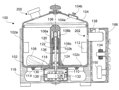
Reference is made to FIG. 1, which illustrates a cross-sectional view of an
embodiment of the present invention, a frying apparatus 100. Frying apparatus
100
comprises a container 102, a lid 104, a coupling device 106, a stirring blade
108, a
power-drive assembly 110, a venting device 200, and a blowing device 202.
8
ma
CA 02449600 2003-11-03
Container 102, having an open top, an outer wall 102a, and an upstanding inner
cylindrical wall 102b, is provided for holding foods and oil. Cylindrical wall
102b is
installed on the central bottom of container 102, so as to emanate from the
bottom
thereof upward to substantially the open top, forming a central aperture
therein.
Container 102 is, preferably, coated with a non-stick material.
One or a plurality of co-rotation preventing blades, generally designated as
112, is
installed inside container 102, on outer wall 102x, for preventing the food
from co-
rotating with stirring blade 108, as blade 108 rotates. Eilades 112, disposed
on
positions slightly higher than blade 108, generally extend vertically. The
size of blades
112 can be substantially different based on specific designs of container 102.
A heating element 114, installed on the outside surface of the bottom of
container 102,
is provided for heating foods and oil disposed inside container 102. Heating
element
114 is in a heat-transferable condition, e.g., in physical contact, with the
bottom of
container 102, such that when heating element 114 heats up upon connection
with an
electricity source, foods and oil therein will also heat up. Heating element
114 can be
electrical resistance type heaters or many other types, such as high-intensity
infrared
lamps, as known to those skilled in the art and suggested by this invention
disclosure.
A container support 116, installed on the bottom and side of container 102, is
provided
for furnishing a bottom support for container 102, such that frying apparatus
100 can
stand on a flat surface, e.g., a kitchen counter top. Another function of
support 116 is
insulating the bottom of container 102. The sidewall of support 116 can extend
upward, covering substantially large area of outer wall 102a of container 102
for
minimizing heating energy loss. In this case, support 116 serves as an outer
housing.
A temperature sensor 118 is provided for measuring the temperature of the
frying oil,
as an input variable to be controlled. Sensor 118 is installed at an
appropriate position
on the bottom of container 102, or any other suitable positions. When the
temperature
of the frying oil is above the user's desired one, the electrical power to
heating
element 114 will be shut down to better meet the user's desired frying
requirement
and to save energy.
9
CA 02449600 2003-11-03
Lid 104 is provided for covering on top of container 102 for closing up the
open top
thereof. Lid 104 can be made of a transparent material, or a metal material
but has an
observation window (not shown), made of a transparent material, for observing
the
frying process by the user.
An opening 104a is provided on lid 104, disposed at a suitable location, for
adding
ingredients to the food inside container 102 by the user in the middle of
frying
processes. A cap 104b is provided for covering up opening 104a.
FIG. 2 illustrates an exploded cross-sectional view of wupling device 106.
Coupling
device 106, having an outer cylindrical wall 106a and an inner cylindrical
wall 106b, is
provided for coupling a main shaft 120 from power-drive assembly 110 and
stirring
blade 108 for transferring rotation power. VIlalls 106a and 106b are
substantially co-
axial to cylindrical wall 102b of container 102 and are fixedly connected
together on
the upper portion thereof. The lower portion of wall 108a is engaged with
blade 108.
The lower portion of wall 106b has a cross-channel coupling element 106c, or
other
types of coupling elements, which lockabiy receives main shaft 120 and a main
shaft
pin 122. Pin 122 is mounted on the upper portion of main shaft 120, running
across a
diameter thereon for coupling main shaft 120 and coupling element 106c. In
operation, wall 106a is routed over wall 102b and wall 102b is routed over
wall 106b.
The upper portion of main shaft 120 threads inside wall 106b. Minimal
clearance is
desired among these walls for ideal performance.
Blade 108, rotatably and removabiy installed inside container 102 on the
central
bottom thereof, is provided for stirring foods. There is a central aperture on
blade 108
to permit threading over cylindrical wall 102b.
A stirring blade spacer 124, fixedly installed on the central bottom of
container 102
around the bottom portion of wall 102b, is provided for supporting blade 108.
FIG. 3 illustrates a cross-sectional view of blade 108 in relation to the
bottom of
container 102. The cross-section generally forms a plow-like configuration.
The front
portion thereof, generally designated as 108a, is close to the bottom of
container 102
CA 02449600 2003-11-03
with a small predetermined clearance for better scooping up food pieces. The
rear
portion thereof, generally designated as 108b, extending gradually upward,
serves for
lifting uplturning over food pieces. The clearance between front portion 108a
and the
bottom of container 102 is minimized for ideal performance.
However, when the clearance is small, it is inevitable that blade 108 will
scrape on the
bottom of container 102, causing worn-out of blade 108 and energy loss due to
friction
of large area. To deal with this dilemma, a plurality of circular protrusions,
generally
designated as 102c, fixedly installed on the bottom of container 102, is
proposed in
this invention disclosure. Reference is made to FIGS. 1 and 2 for the
configuration of
protrusions 102c. Protrusions 102c provide further support to blade 108, in
addition to
spacer 124, which is more clearly shown in FIG. 2. A predetermined small width
of
protrusions 102c is desired for providing adequate support and, at the same
time,
minimizing friction. in the case for a container coated with a non-stick
material, the top
surface of protrusions 102c is, preferably, not coated. Local areas on blade
108,
which are in the vicinity of protrusions 102c, can have a different material
for durability
consideration. The height of protrusions 102c is, preferably, small, e.g.,
less than 1
mm, for ideal performance of blade 108 in scooping up food pieces and avoiding
sticking. Protrusions 102c can readily have many other configurations, or
patterns.
The speed, at which blade 108 sweeps across food pieces, is important. For too
low
speeds, blade 108 cannot scoop up food pieces and therefore food pieces cannot
be
agitated adequately to achieve the desired effect of homogeneous heating and
the
evaporation of food moisture. Co-rotation of food pieces with blade 108, as
blade 108
rotates, is going to be a big issue. Therefore, a higher :;peed is desirable
for good
performance. But, on the other hand, for continuous operation of blade
sweeping,
when the speed is high, food pieces are agitated too much, for too long time,
such that
the crispy surfaces of food pieces are damaged, which, in turns, causes frying
oil to be
wasted due to too many tiny food particles in the oil. In addition, the worn-
out of blade
108 and energy loss due to friction between blade 108 and the bottom of
container
102 are going to be serious problems.
To solve this dilemma, an intermittent operation of blade sweeping is proposed
in this
invention disclosure. In this intermittent operation, blade 108 dwells for a
11
CA 02449600 2003-11-03
predetermined interval of tirne after one or two rounds of sweeping, referred
as one
stirring cycle, and then automatically begins another cycle of operation. This
intermittent operation affords relief from constant stirring of food pieces at
a higher
speed, prolongs the utility life of blade 108 and power-drive assembly 110,
and saves
some energy required for driving blade 108, as compared with the continuous
operation. This intermittent operation also favors foods of great texture
because
during the dwell period, the food pieces have adequate time to form crispy
surfaces;
which, in turns, favors foods of great looking. A computer control method and
an
electronic control circuit for achieving this intermittent operation are going
to be
disclosed later on, when the control portion of frying apparatus 100 is
discussed.
Reference is, again, made to FIG. 1. Power-drive assembly 110 includes a drive
motor 126 and main shaft 120.
A motor housing 128, having an open top, is provided for housing motor 126.
Motor
housing 128 is installed on the central bottom of support 116. A cap 130 is
provided
for covering on top of motor housing 128 for closing up the open top thereof.
There is
a central aperture on cap 130 for permitting main shaft 120 to thread
therethrough.
Motor 126 is installed inside motor housing 128 through a bracket 132 and is
operationally connected to a DC adapter 134.
Main shaft 120 is operationally coupled with motor 126, directly for a low-
speed motor
or via some gears or belt-pulley devices for a high-speed motor. Main shaft
120 is
substantially co-axial to cylindrical wall 102b and threads therein, so as to
emanate
from the bottom of container 102 to substantially the upper portion of wall
102b.
Reference is made to FIG. 2, again. On the upper portion of main shaft 120,
coupling
pin 122 is provided for the engagement with coupling element 106c of coupling
device
106. Pin 122 has a predetermined length so as to conveniently slide in the
opening on
the lower portion of cylindrical wall 106b for removably locking on coupling
element
106c.
12
CA 02449600 2003-11-03
A plurality of main shaft supporting elements, generally designated as 136,
installed
on the upper portion of main shaft 120, is provided for further supporting
main shaft
120, against cylindrical wall 102b. Elements 136 havE: a ring-like
configuration and
are slidably threaded inside cylindrical wall 102b, together with main shaft
12U. The
clearance between elements 136 and cylindrical wall 102b is minimized for
ideal
performance. Bearings are ideal options for elements 136 for minimizing power
loss
due to friction.
Reference is, now, made to FIG. 4 and FIG. 5, which illustrate an embodiment
of a
forced venting system including a venting device 200 and a blowing device 202
of
FIG. 1.
Venting device 200 includes a venting conduit 206 and a venting filter 208.
The first
end of venting conduit 206 is mounted on lid 104. There is an opening on lid
104 inline
with venting conduit 206 for allowing cooking fumes to be forced out
therethrough.
Venting conduit 206 also serves as a bracket for holding venting filter 208.
Venting
filter 208 is removably engaged with the second end of venting conduit 206.
Venting
filter 208 further includes a disposable paper filter 208a and/or a disposable
activated
charcoal filter 208b, together, as an integrated filter.
Venting filter 208 is provided to trap the grease impurities in the grease-
laden air
forced out from inside frying apparatus 100. Venting filter 208 is,
preferably, made of
one or multiple layers of metal meshes, such as aluminum ones. Metal meshes
have
different sizes of meshes and overlap each other. When cooking fumes pass
therethrough, the oil particles will be trapped thereon. Filters 208a and 208b
are
provided to further remove the remaining oil vapor and chemical contents in
the
cooking fumes and for removing the cooking fume odors before the air is
exhausted
into the room.
Blowing device 202 includes an in-take conduit 210, a blowing motor 214, a fan
216,
and a one-way valve 218.
The first end of in-take conduit 210 is mounted on the upper portion of
container 102.
There is an opening on the sidewall of container 102 inline with in-take
conduit 210 for
13
CA 02449600 2003-11-03
allowing fresh air to be forced into frying apparatus 100. There is an
aperture 212 on
in-take conduit 210. Aperture 212 functions as an air inlet. An inlet conduit
210a
extends from aperture 212 to the outside space, such that fresh air from
outside
atmosphere can be readily drawn into frying apparatus 100. A filter 21 Ob,
made from
metal meshes, is provided for preventing some large particles from being drawn
therein. In-take conduit 210 also serves as a bracket for holding motor 214 in
position.
Motor 214 is removably coupled with the second end of in-take conduit 210. Fan
216
is connected to motor 214 on the shaft and inserted inside in-take conduit
210. Motor
214 is operationally connected to adapter 134, which i;~ shown in FIG. 1.
As shown in FIG. 6, which illustrates an exploded cross-sectional view of one-
way
valve 218 of FIG. 5. Valve 218 includes a valve housing 220, a valve body 222,
a
covering piece 224, and a biasing spring 226. Valve housing 220 is engaged
with the
first end of in-take conduit 210. There are apertures on valve housing 220 for
allowing
air to pass therethrough. Valve body 222 is engaged with the open end of valve
housing 220. There are apertures on valve body 222 for allowing air to pass
therethrough. Covering piece 224 covers on valve body 222 for closing and
opening
valve 218. There is a central protrusion on covering piece 224. The central
protrusion
is slidably inserted into a central aperture on valve body 222, such that the
protrusion
can slide along the central aperture for a predetermined distance. Spring 226
is
attached between the protruding end of the protrusion and valve housing 220,
such
that spring 226 is biased in slight tension, thereby, pulling covering piece
224
toward/against valve body 222 for closing up valve 218.
When blowing device 202 is in working condition, the air pressure generated by
fan
216 forces covering piece 224 to slide away from valve body 222, such that
valve 218
is in opening state for allowing air to pass therethrough. Valve 218 is
provided for
preventing cooking fumes inside frying apparatus 100 from escaping through
kalowing
device 202 while blowing device 202 is temporarily not in working condition.
Those skilled in the art will appreciate in view of this invention disclosure
that many
other suitable valve designs are readily applicable for this application of
the present
invention.
14
CA 02449600 2003-11-03
Venting device 200 and blowing device 202 can be alternatively installed on
frying
apparatus 100 at many other positions. For example, venting device 200 can ire
alternatively installed on the upper portion of container 102 and blowing
device 202
can be alternatively mounted on lid 104. These variations are; therefore,
covered by
this invention disclosure.
Venting device 200 is provided for cooking fume treatment. Compared with prior
art
products, which allow cooking fumes to escape freely, this centralized venting
system
design vents cooking fumes in a controlled manner, such that heating energy is
better
preserved for a more efficient frying apparatus.
Blowing device 202 is provided for forcing moisture content out of frying
apparatus
100, especially at the early stage of a frying process, such that frying
apparatus 100
can fry foods of great taste, great texture, and great looking. This also
favors less
cooking time and, as a result, less energy consumption. However, there is some
heating energy loss associated with using blowing device 202. Therefore, the
use of
blowing device 202 should be in a controlled manner.
Stronger blowing favors better inside airflow for better facilitating moisture
removal.
However, Continuously strong blowing will cause excessive heating energy loss.
To
solve this dilemma, an intermittent venting operation is proposed in this
invention
disclosure. In this intermittent venting operation, fan 216 dwells for a
predetermined
interval of time near the end of a blowing cycle, e.g., of 10 seconds, and
then
automatically begins another cycle of operation. An electronic control circuit
for
achieving this intermittent operation is going to be disclosed later on, when
the control
portion of frying apparatus 100 is discussed.
Immediately after the frying is satisfactorily accomplished, the food is still
sizzling hot
and there is still residual cooking fume residing inside trying apparatus 100.
Blowing
device 202 can be used to bring in fresh air to cool the food down to a
predetermined
temperature and, at the same time, to purge the residual cooking fumes out
through
venting device 200. This process greatly favors safety of food handling, home
environment protection, and foods of great texture and looking.
CA 02449600 2003-11-03
The above-discussed forced venting system is good for both deep and shallow
frying.
For deep-frying it facilitates the evaporation for food surface moisture. For
shallow
frying, especially for frying vegetables, it favors foods of great looking. It
is a well-
known fact that when fried using a conventional frying pan with the lid
covering on top
thereof, green vegetables tend to become yellowish.
Reference is made to FIG. 1, again. A control housing 138 is provided for
housing a
control module 150. Control housing 138 is installed on the sidewall of
container 102.
Control module 150, installed inside housing 138, is provided for controlling
various
functions of frying apparatus 100, such as the oil temperature for frying
foods, motor
speeds for rotating blade 108, and the speed at which blowing motor 214 is
rotating.
Control module 150 includes a control circuit 152, as the blocked construction
diagram
shown in FIG. 7. Circuit 152 comprises a microcomputer 154, which controls
various
functions of frying apparatus 100, a relay 156, which activates heating
element 114, a
relay 158, which activates motor 126, and a relay 160, which activates motor
214.
Microcomputer 154 is provided with ROM and RAM for data memory, and further
provided with I/O ports AID converters as interfaces. The aforementioned ROM's
comprises a ROM 162 containing control programs related to the performance of
all
frying processes and a ROM 164, which memorizes referenced data.
Temperature sensor 118 is provided for measuring the oil temperature, which is
taken
by microcomputer 154, as an input variable to be controlled. When the
temperature of
the frying oil is above the user's desired one, the electrical power to
heating element
114 will be shut down by relay 156 to better meet the user's desired frying
requirement and to save energy.
Computer 154 can be such programmed that relay 158 activates motor 126
intermittently with a bias toward a longer dwell after each stirring cycle of
one or two
rounds of rotation. In the same manner, an intermittent venting operation can
be
programmed with relay 160 activating motor 214 intermittently.
16
CA 02449600 2003-11-03
DC adapter 134 is installed inside control housing 138, as shown in FIG. 1.
Adapter
134 provides electricity power to control circuit 152 and elements, like
indicators,
beepers, LCD, etc., and to motors 126 and 214, as well.
A control panel 166, attached to control housing 138, as shown in FIG. 1, is
provided
for supporting elements, like switches, indicators, adjusting knobs, beepers,
LCD, and
so on.
Reference is made to FIG. 8, which illustrates a schematic diagram of a
control circuit
50 for providing the intermittent operation of blade sweeping for frying
apparatus 100.
As shown in FIG. 8, drive motor 126 is operationally coupled with blade 108
far
providing rotation power. Motor 126 has a first terminal, which is connected
to V-, the
negative pole of a power source, e.g., DC adapter 134, which is shown in FIG.
1, and
a second terminal, which is connected to the collector terminal of a PNP
bipolar
transistor 51. The emitter terminal of transistor 51 is connected to V+, the
positive pole
of a power source, e.g., DC adapter 134, which is shown in FIG. 1. Associated
with
motor 126 is a linkage mechanism 52, which cooperatE~s with a single pole,
double
throw switch 53, such that the shaft angle of motor 126 controls the switching
position.
Switch 53 includes a single pole 54, which is connected to the first end of a
capacitor
55. Pole 54 may be switched alternately between two throw positions as
represented
by RUN and REST. The reference RUN refers generally to the position of blade
108
when in sweeping. On the other hand, the reference REST refers generally to
the
position of blade 108 when in dwelling. The RUN position represents
substantially a
large portion of a whole round of rotation angle of the motor shaft, e.g.,
over 8l~%. The
RUN position is associated with V- and the REST position is associated with
V'+.
A main switch 56 is provided for activating and deactivating the intermittent
operation
provided by circuit 50. Switch 56 has a first terminal connected to V- and a
second
terminal connected to the first end of a variable resistor 58.
The second end of capacitor 55 is connected to the second end of resistor 58.
Also
connected to the second end of capacitor 55 are the base of transistor 51 and
the
second end of a resistor 59. The first end of resistor 59 is connected to the
first
17
CA 02449600 2003-11-03
terminal of a STIR switch 60, which can activate a STIR feature, a manually
activated
continuous operation. The second terminal of switch 60 is associated with V-.
The first
end of resistor 59 is also connected to the second end of a capacitor 61. The
first end
of capacitor 61 is connected to V-.
Switch 60 is a push button switch for activating the STIR feature. When switch
60 is
pushed, the two terminals are connected, which causes the connection of the
first end
of resistor 59 to V- and, at the same time, causes capacitor 61 to be short-
circuited.
With switch 56 in the activated position and switch 60 in the deactivated
position,
circuit 50 will operate blade 108 intermittently with a variable dwell period
at the end of
each sweeping cycle. This intermittent operation is achieved through the
circuit of
transistor 51, switch 53, capacitor 55, and resistor 58.
Now, to start with, suppose motor 126 has not been operating because switch 56
has
been in the deactivated position. Also suppose switch 53 has been in the REST
position, and thus capacitor 55 has been discharged.
When switch 56 is activated, the potential at the second end of resistor 58
will be
lowered to cause transistor 51 to switch to conductive state, thereby
energizing motor
126. As soon as motor 126 begins to rotate, switch 53 will be thrown to the
RUN
position, which causes the first end of capacitor 55 to be connected to V-.
Capacitor
55 will then begin to charge so as to make the second end of capacitor 55
positive
with respect to the first end thereof. Sufficient base current will be
provided through
the base of transistor 51 to cause transistor 51 to remain conductive even
after
capacitor 55 becomes fuNy charged, thereby causing motor 126 to continue to
rotate
throughout a full rotation cycle until switch 53 is cycled back to the REST
position.
When switch 53 cycles back to the REST position, the first end of capacitor is
then
connected to V+ and capacitor 55 begins to discharge through resistor 58 until
the
potential at the second end of resistor 58 becomes sufficiently negative
relative to V+.
During this period of time, transistor 51 is switched to and remains in non-
conductive
state, thereby stopping motor 126 for a predetermined interval of time. And
then;
sufficient base current flow resumes, causing transistor 51 to become
conductive
again, and a new cycle starts.
18
CA 02449600 2003-11-03
The length of the dweN interval is determined by the time required for
capacitor 55 to
discharge. Proper selection of capacitor 55 and resistor 58 will provide
desirable dwell
intervals.
With resistor 59 and capacitor 61 in addition, a manually activated continuous
blade-
sweeping feature can be achieved in addition to and in combination with the
controllable variable dwell feature. This performance feature is achieved
regardless of
whether switch 56 is in the activated position or not when switch 60 is
pushed.
Moreover, it will be seen if switch 56 is in the activated position when
switch 60 is
pressed, there will be an immediate override of the intermittent operation.
The
continuous operation will keep on going without any dwell for a predetermined
number
of cycles, for example, one or two, after switch 60 is released, before the
intermittent
operation is resumed. If switch 56 is in the deactivated position when switch
60 is
pressed, motor 126 will immediately start to rotate. After switch 60 is
released, motor
126 will continue for a predetermined number of continuous sweeping cycles and
then
stop.
When switch 60 is pressed, the first end of resistor 59 is connected to V-.
This. allows
sufficient current to flow thraugh the base of transistor 51 to switch
transistor 51 to
conductive state, thereby causing motor 126 to start and operate. By proper
selection
of the value of resistor 59, this mode of operation will occur regardless of
the positions
of switches 53 and 56, so long as switch 60 is depressed.
At the same time, pressing switch 60 causes capacitor' 61 to be short-
circuited such
that any charge stored therein is discharged through the short circuit to V-.
When
switch 60 is released, the current flow out of the base of transistor 51 will
continue
through discharged capacitor 61 until capacitor 61 recharges. As a result,
transistor 51
will continue in conductive state and motor 126 will continue to operate at
the normal
speed. Transistor 51 will continue in conductive state for a predetermined
period of
time based on the time constant provided by resistor 59 and capacitor 61,
which are
preferably selected to provide one or two continuous sweeping cycles without
any
dwell after switch 60 is released.
19
CA 02449600 2003-11-03
One important point worth mentioning is that if power-drive assembly 110 has a
rotation reduction mechanism, linkage 52 should be set between the output
shaft of
assembly 110 and switch 53, instead of between motor 126 and switch 53.
If multiple rounds of sweeping are desired for a stirring cycle, before one
dwell period,
e.g., two rounds of sweeping before one dwell period, a pair of gears, or some
other
mechanisms, should be provided, with the smaller one installed on the output
shaft
and the larger one cooperating with switch 53. The transfer-ratio should be
1:?.
The intermittent operation of blade sweeping can be alternatively achieved
using a
mechanically controlled timer, e.g., a spring-driven timer (not shown).
Numerous
discrete contact poles can be provided on a circular plate, such that when a
needle is
rotating around a central shaft, the needle engages with each contact pole in
sequence. The angle range of each pole represents a stirring cycle. At the end
of
each stirring cycle, there is a predetermined dwell period, which is
represented by the
angle range in between two adjacent poles.
Reference is made to FIG. 9, which illustrates a scherr~atic diagram of a
control circuit
70 for providing the intermittent venting operation for frying apparatus 100.
As shown in FIG. 9, blowing motor 214 is operationally coupled with fan 216
for
forcing fresh air into frying apparatus 100. Motor 214 has a first terminal,
which is
connected to V-, and a second terminal, which is connected to the collector
terminal of
a PNP bipolar transistor 71. The emitter terminal of transistor 71 is
connected to V+.
The base of transistor 71 is connected to the second end of a variable
resistor 72. The
first end of resistor 72 is connected to the second end of a capacitor 73. The
first end
of capacitor 73 is connected to V-.
Also connected to the first end of resistor 72 are the second terminal of a
magnetically
activated switch 74 and the first terminal of a VENT switch 75. The first
terminal of
switch 74 and the second terminal of switch 75 are connected to V-.
Switch 74 is provided for activating and deactivating the intermittent venting
operation
provided by circuit 70. Switch '74 cooperates with motor 126, such that when
motor
i, i
CA 02449600 2003-11-03
126 is in working state, switch 74 is activated and remains in activated
condition until
motor 126 ceases to work. Switch 75 is a push button switch, which is provided
for
activating a manually activated continuous venting feai:ure.
When either switch 74 or switch 75 is activated, the first end of resistor 72
is
connected to V- and, at the same time, capacitor 73 is short circuited to V-.
With switch 74 in the activated position and switch 75 in the deactivated
position,
circuit 70 will operate fan 216 intermittently with a variable dwell period at
the end of
each venting cycle. This intermittent venting operation is achieved through
the circuit
of transistor 71, resistor 72, capacitor 73, and switch 74, which is
conditioned by motor
126.
When motor 126 is in working state, switch 74 is activated, such that the
first end of
resistor 72 is connected to V-, and capacitor 73 is short circuited to V-. The
potential
at the second end of resistor 72 is lowered to cause transistor 71 to switch
to
conductive state, thereby energizing motor 214. As soon as motor 126 stops,
switch
74 is deactivated. The current flow out of the base of transistor 71 will
continuE;
through discharged capacitor 73 until capacitor 73 recharges. As a result,
transistor 71
will continue in conductive state and motor 214 continue to operate at the
normal
speed. Transistor 71 will continue in conductive state for a predetermined
period of
time based on the time constant provided by resistor 72 and capacitor 73,
which are
preferably selected to provide a multiple of a sweeping cycle of blade 108,
e.g., five
continuous blade sweeping cycles. Motor 214 then dwells for a predetermined
interval
of time until the next cycle of the intermittent operation of blade 108
starts, when
motor 126 activates switch 74, again.
With switch 75 in addition, a manually activated continuous venting
performance
feature can be achieved in addition to and in combination with the
controllable variable
dwell feature. This performance feature is achieved regardless of whether
switch 74 is
in the activated position or not when switch 75 is pushed. Moreover, it will
be seen if
switch 74 is in the activated position when switch 75 is pressed, there will
be an
immediate override of the intermittent venting operation. The continuous
operation will
keep on going without any dwell for a predetermined interval of time after
switch 75 is
21
CA 02449600 2003-11-03
released, before the intermittent venting operation is resumed. If switch 74
is in the
deactivated position when switch 75 is pressed, motor 214 will immediately
start to
rotate. After switch 75 is released, motor 214 will continue for a
predetermined interval
of time, and then stops.
FIG. 10 illustrates a perspective view of a perforated basket 168 for use with
frying
apparatus 100. Basket 168, provided primarily for deep-frying foods, is
preferably
cylindrical in configuration and has an upstanding inner cylindrical wall 168a
defining a
central aperture, a plurality of open slots, generally de signated as 168b,
for removably
receiving blades 112, as shown in FIG. 11, and a basket handle 168c for
handling
basket 168.
FIG. 11 illustrates a cross-sectional view of basket 16Ft in an operation
position. Wall
168a is installed on the central bottom of basket 168, so as to emanate up
toward the
upper portion thereof, and removabfy receives cylindrical wall 102b
therethrough.
Slots 168b slidably receive blades 112, and whereby basket 168 is maintained
in
position. Handle 168c is installed on the upper portion of basket 168. A
plurality of
small recessions, disposed on the upper edge of container 102, are provided
1:o allow
the metal rods connecting the main body of handle 168c and the main body of
basket
168 to extend from inside to outside of frying apparatus 100. Wall 168a is
routed over
wall 102b and wall 106a is routed over both walls 102b and lf8a.
Reference is made to FIG. '12, which illustrates an alternative design of
frying
apparatus 100 of FIG. 1, a frying apparatus 100a. In this alternative design,
a heating
element support bracket 170 is provided for supporting heating element 114.
Bracket
170 is removably supported by container support 116. Heating element 114 is
fixedly
installed on bracket 170. Temperature sensor 118 is installed on cap 130 or
some
other suitable components. Container 102 is removably installed inside
container
support 116, such that container 102 can be easily taken out for food and used
oil
handling and for cleaning after use. When container 102 is secured inside the
opening
of support 116 in an operating position, heating element 114 and sensor 118
are in
physical contact with the bottom of container 102.
In operation, a user,
22
CA 02449600 2003-11-03
First, Installs container 102 in working position on container support 116 and
secures
stirring blade 108 in position.
Second, charges container 102 with oil, and then preheats the oil to a
predetermined
temperature, preferably, halfway boiling. This step can be one step of a
cooking
program.
Third, charges container 102 with the food to be fried and covers container
102 with
lid 104 for closing up the open top of container 102.
Fourth, selects an oil temperature, a time duration, a stirring blade rotation
speed, and
a blowing motor speed, or a program for frying foods, and then pushes on start
button
for activating the frying process.
Fifth, removes stirring blade, and then unloads the prepared food.
The whole frying process is hand-free. The user does not have to be involved
with the
frying process until the frying is accomplished. The frying apparatus will
then beep to
remind the user when the frying process is done. The fried food is, now, ready
for
serving.
Reference is made to FIG. 13, which illustrates a cross-sectional view of
another
embodiment of the present invention, a frying apparatus 300. Some components
or
devices of frying apparatus 300 are similar to those of frying apparatus 100.
Similarity
is in the sense of both functionality and configuration. Therefore, similar
components
or devices are denoted with similar reference numbers for avoiding repetitive
explanations. Reference is made to frying apparatus 100 of FIG. 1 for detailed
information about these similar components or devices.
A container 302, having an open top, is provided for holding foods and cooking
oil. A
central aperture is provided on the bottom of container 302 for allowing a
main shaft
304 to thread therethrough.
23
CA 02449600 2003-11-03
A coupling device 306, having a hollow cylindrical lower portion, is provided
for
coupling main shaft 304 and stirring blade 108 for transferring rotation
power. The
lower portion of coupling device 306 is fixedly engaged with blade 108. The
lower
portion of coupling device 306 also has a cross-channel coupling element 306a,
or
other types of coupling elements, which lockably receives main shaft 304 via
pin 122.
The upper end of coupling device 306 extends upward to substantially the open
top of
container 302. In operation, the upper portion of main shaft 304 threads
inside the
inner opening of the lower portion of coupling device 306. Minimal clearance
is
desired between main shaft 304 and the cylindrical wall of the lower portion
of
coupling device 306 for ideal performance.
The lower end of shaft 304 has an inner gear 304a, as more clearly shown in
FIG. 14,
for removably receiving a motor shaft 126a, which has a square or gear head,
such
that the lower end of shaft 304 loosely and removably engages with motor shaft
126a.
This kind of coupling dramatically reduces the co-axial requirement on main
shaft 304
and motor shaft 126a and facilitates the assembly process for manufacturing.
A seal assembly 308 is provided for sealing between shaft 304 and container
302, as
shown in FIG. 14, which illustrates an exploded cross-sectional view of seal
assembly
308. Seal assembly 308 comprises a seal flange 310, a gland nut 312, and a
compression packing 314.
Flange 310 is co-axial to shaft 304. The first end of flange 310 is sealingly
installed on
the outside surface of the central bottom of container 302. Gland nut 312 is
engaged
with the second end of flange 310 by means of screw. Packing 314 creates a
seal by
being squeezed between the throat of the stuffing box 'formed by flange 310
and gland
nut 312. The squeeze force pushes the material against the throat of the box
and
rotating shaft 304.
When leakage occurs, gland nut 312 is tightened further. This is a typical
application
of compression packings for low speed rotating shafts, such as shaft 304.
Materials are extremely important when selecting the proper packing for an
application. Metallic packings are used in high-temperature applications.
Shafts for
24
CA 02449600 2003-11-03
copper and aluminum packings must be hardened to 500 Brinell hardness number
(Bhn). Copper and aluminum packings can handle 531:3°C (1000°F)
application
temperature.
Seal assembly 308 can, alternatively, take many other forms, such as bushing
and
labyrinth seals, or combinations of multiple forms for ideal performance, as
known to
those skilled in the art and suggested by this invention disclosure.
FIG. 15 illustrates an exploded cross-sectional view of an alternative design
of seal
assembly 308 of FIG. 14. In this alternative design, sea! assembly 308 is
installed
inside container 302 on the central bottom thereof, instead of being installed
on the
outside bottom of container 302. The first end of flange 310 is fixedly
installed on the
inner surface of the bottom of container 302 and the second end of flange 310
extends upward to a predetermined height above. Gland nut 312 and compression
packing 314 are engaged with the second end of flange 310.
There is an important advantage of the alternative design illustrated by FIG.
15. For
most applications, seal assembly 308 is higher than the oil level, such that
the sealing
surface is not immersed in cooking oil or hot liquid. Therefore, the
requirement on seal
assembly 308 is significantly reduced. In addition, shaft 304 is much better
supported
at a higher level. In operation, the lower portion of coupling device 306 is
routed over
sea( assembly 308.
Other features of frying apparatus 300 are similar to those of frying
apparatus 100.
Reference is made to FIG. 16, which illustrates an alternative design of
frying
apparatus 300 of FIG. 13, a frying apparatus 300a. In this alternative design,
a heating
element support bracket 170 is provided for supporting heating element 114.
Bracket
170 is removably supported by container support 116. Heating element 114 is
fixedly
installed on bracket 170. Temperature sensor 118 is installed on cap 130 or
some
other suitable components. Container 302 is removably installed inside
container
support 116, such that container 302 can be easily taken out for food and used
oil
handling and for cleaning after use. When container 302 is secured inside the
opening
;.i
CA 02449600 2003-11-03
of support 116 in an operating position, heating element 114 and sensor 118
are in
physical contact with the bottom of container 302.
Other features of frying apparatus 300a are similar to those of frying
apparatus 300.
Reference is made to FIG. 17, which illustrates a cross-sectional view of a
further
more embodiment of the present invention, a frying apparatus 400. Some
components
or devices of frying apparatus 400 are similar to those of frying apparatus
100.
Similarity is in the sense of both functionality and configuration. Therefore,
similar
components or devices are denoted with similar reference numbers for avoiding
repetitive explanations. Reference is made to frying apparatus 100 for
detailed
information about these similar components or device;.
A container 402, having an open top and a closed bottom, is provided for
holding
foods and cooking oil. A central shaft 404 is provided for guiding a coupling
device
406 in position. The lower end of shaft 404 is fixedly installed on the
central bottom of
container 402 and the upper end thereof extends upward toward the open top of
container 402.
Coupling device 406 is provided for operationally transferring rotation power
from a
power-drive assembly 408 to stirring blade 108. Coupling device 406 has a
general .
configuration of a cylindrical tube forming a central aperture routed over
shaft 404.
The lower end of coupling device 406 is engaged with blade 108 and the upper
end
thereof extends upward to substantially the open top of container 402. A
coupling
element 406a is provided on the upper portion of coupling device 406 for
transferring
rotation power.
A motor housing 410, disposed above lid 104, is pivotally installed on the
upper
portion of control housing 138 via a hinge 412. Housing 410 maintains
substantially
horizontal when secured in an operational position and can be conveniently
lifted up
via a handle 414.
A drive motor 416 is installed inside housing 410. A motor pulley 418 is
fixedly
engaged on the motor shaft for transferring rotation power from motor 416 to a
main
26
CA 02449600 2003-11-03
shaft 420 via a belt 422 and a drive pulley 424. NPain shaft 420 is installed
onto
housing 410 via a plurality of bearing elements, generally designated as 426.
The
lower end of shaft 420 extends downward through the floor of housing 410. A
coupling
element 428, fixedly engaged on the lower portion of shaft 420 outside housing
410, is
provided for driving an intermediate coupling device 430, which is installed
on lid 104.
Coupling device 430 includes an intermediate shaft 432, an upper coupling
element
434, and a lower coupling element 436.
The upper end of shaft 432 is fixedly engaged with coupling element 434, which
is
removably coupled with coupling element 428. Coupling element 434 can be
specially
designed, such that couple element 434 also serves as a lid handle. The
lowe~° end of
shaft 432 extends downward through a central aperture on lid 104 and is
fixedly
engaged with coupling element 43f>, which is removably coupled with coupling,
element 406a.
Intermediate coupling device 430 is rotatably installed on lid 104 via a
bearing element
438.
Other features of frying apparatus 400 are similar to those of frying
apparatus 100
Reference is made to FIG. 18, which illustrates an alternative design of
frying
apparatus 400 of FIG. 17, a frying apparatus 400x. In this alternative design,
a~ heating
element support bracket 170 is provided for supporting heating element 114.
f8racket
170 is removably supported by container support 116. Heating element 114 is
fixedly
installed on bracket 170. Temperature sensor 118 is installed on container
support
116, or some other suitable components. Container 402 is removably installed
inside
container support 116, such that container 402 can be easily taken out for
food and
used oil handling and for cleaning after use. When container 402 is secured
inside the
opening of support 116 in an operating position, heating element 114 and
sensor 118
are in physical contact with the bottom of container 402.
Other features of frying apparatus 400a are similar to those of frying
apparatus 400
27
CA 02449600 2003-11-03
For all the embodiments discussed above, when the container is large, the
stirring
device is consequently big, such that it may not be quite convenient to use or
handle.
In order to solve this problem, far the frying apparatus having a large
container, the
lower portion of the container can be adapted to taper inward, such that the
bottom of
the container has a smaller diameter. Consequently, the stirring device can be
designed smaller.
Accordingly, readers will see that this frying apparatus of the present
invention can be
used to prepare tasteful fried foods for both deep and shallow frying. The
frying
process is fully automatic, thereby minimizing human involvement and chore of
the
frying process. This frying apparatus is used with the lid fully covering on
top of the
container, thereby eliminating the possibility of grease splattering and the
risk of oil
burns to people. At the same time, the grease-laden air generated during the
frying
process is forced out through a venting device and filtered before being
discharged
into the room, thereby avoiding long-term hazards to the people and home
environment.
The stirring blade sweeps across food pieces intermittently, such that the
blade dwells
for a predetermined dwell period starting near the end of each stirring cycle.
This
intermittent operation favors better agitation of food pieces and affords
relief from
constant stirring at a higher speed.
The present invention has been described in an illustrative manner. It is to
be
understood that the terminology, which has been used, is intended to be in the
nature
of words of description rather than of limitation.
Although this invention has been described in its preferred forms and
structures with a
certain degree of particularity, these should not be con;~trued as limiting
the scope of
the invention but as merely providing illustrations of some of the presently
preferred
embodiments of this invention.
For examples, although this invention has been described in a form of home
frying
apparatuses, it can have potential business use, such as use in restaurants.
Therefore, this invention can alternatively be described as food processing
equipment
28
CA 02449600 2003-11-03
Although the forced venting system of this invention has been described in a
form of
blowing fresh air into the frying apparatus, it is understood that
rearrangement of the
motor, fan, and filters, such that, instead of blowing fresh air into the
frying apparatus,
the fan actually draws the moisture-laden and grease-laden air out of the
frying
apparatus, is perfectly inline with the spirit of the forced venting concept
of this
invention. Such rearrangement is, therefore, covered by the present invention.
Thus it is understood that the present disclosure of the preferred forms can
be
changed in the details of construction and in the combination and arrangement
of
parts without departing from the spirit and the scope of the invention as
hereinafter
claimed.
29