Note: Descriptions are shown in the official language in which they were submitted.
CA 02449657 2003-12-03
WO 03/000379 PCT/FI02/00537
1
METHOD AND APPARATUS FOR CLARIFYING A SLURRY
This invention relates to a method of clarifying and/or thickening a solution
containing solids i.e. a slurry, and the apparatus for accomplishing this.
s Using the method and apparatus of the present invention, the flocculant to
be fed into the clarification and thickening equipment is mixed evenly and
with a small shear force into the slurry in the feedwell of the apparatus. The
feedwell is equipped with a mixing device. The slurry is taken onwards from
the feedwell evenly into the clarification tank inside underflow layer, which
io enables the separation of a clear overflow solution.
The clarifying and thickening apparatus comprises a tank, into which the
slurry to be clarified is fed via a feedwell, which is located in the centre
of the
clarification tank, generally in its upper section. When the term
clarification is
is used later in the specification of the invention, it is used however to
refer also
to thickening, since the methods and apparatus described can be applied for
both purposes. The diameter of the clarification tank is ten times larger than
that of the feedwell. In addition to the slurry a flocculant used in
clarification
is fed into the feedwell. The flocculant is often mixed into the slurry while
it is
2o being fed into the feedwell. The clarification or thickening tank may be
equipped with a rake operating near the bottom, or function without one.
The clarified liquid, or overflow, is removed from the clarification tank as
an
overflow and the thickened slurry, or underflow, is removed from the central
2s part of the bottom, to where it has been moved by the rake arms. The tank
bottom of a thickening tank is usually inclined, i.e. sloping down towards the
centre, whereby the removal of solids is made easier. The number of arms in
the rake can be varied depending on the design solution. Some of the rake
arms may be the length of the tank radius, others may be shorter. Vertical
so plates are fixed to the rake arms, and they move the slurry from the edges
towards the centre. They are fixed either perpendicularly to the rake arm or
for example at an angle of 30 degrees to it.
CA 02449657 2003-12-03
WO 03/000379 PCT/FI02/00537
2
In the prior art the feeding of slurry into a feedwell can be performed in
various ways. In the publication: Probst, A.: "Next generation sedimentation
equipment for ultimate thickening", Proceedings of Copper 99 International
s Environment Conference, Vol. II, October 10-13, 1999, Phoenix, Arizona,
USA, pp. 217 - 232, a feed method is described where the feed occurs
tangentially. A flocculant is injected into the feedwell either in a
tangential,
double-elevation slurry feed or it is mixed into the slurry before the
feedwell.
The slurry is removed from the lower section of the feedwell using the venturi
to effect. In the apparatus described in US patent 5,269,928 the slurry is fed
into the feedwell via the central section of the bottom of the thickening tank
and removed to the thickening tank via apertures located in the wall of the
feedwell.
is When the mixing of the flocculant into the slurry occurs in the feedwell
with
only for instance the mixing achieved by a tangential feed, it is clear that
the
flocculant does not mix evenly and that the local shear forces become large.
However, the flocculants used in the present day are large-molecule
polymers whose action is hindered as shear forces increase. If the slurry to
2o be transferred to the clarification tank from the feedwell is discharged
there
forcefully, there is a danger that it will be aimed basically upwards in the
direction of the smallest pressure and thus be mixed into the separated,
already clarified overflow in the upper section of the tank. The clarification
or
thickening tank rakes usually function so that they have an "overlarge"
2s displacement capacity, whereby they press the thickened slurry to the
centre
of the tank, where a pile rises that is higher than the rest of the slurry.
A method and apparatus has now been developed to clarify and/or thicken a
solution containing solids, whereby the slurry is first fed into a feedwell
3o situated in the centre of the upper section of the settling space for
clarification, where a flocculant is mixed into the slurry in the said
feedwell.
From the feedwell the slurry is fed to the settling space and the settled
solids
CA 02449657 2003-12-03
WO 03/000379 PCT/FI02/00537
3
or underflow is removed via a discharge port in the centre of the settling
space and the clarified solution removed as an overflow. The flocculant and
slurry are fed into the feedwell as a gentle stream and are mixed into each
other using the feedwell's own mixing element, after which the mixed slurry is
s guided from the feedwell to the settling space in the upper part of the
underflow layer as a downward directed flow. The apparatus is comprised of
a clarification and/or settling tank, which is equipped with a feedwell for
the
slurry to be settled, a discharge port for the settled solids or underflow in
the
centre of the settling tank, a discharge launder for the clarified solution or
to overflow, and a rake system rotating on its shaft for moving the underflow
from the edges towards the centre. The feedwell is equipped with a mixing
element rotating on its shaft and a guiding cone for the slurry fixed to the
lower section of the feedwell. The essential features of the invention will be
made apparent in the attached claims.
The slurry to be fed into the clarification-thickening tank feedwell is
flocculated using small shear forces in mixing and thus prevents the
disturbance of the flocculant action is prevented. The slurry is fed into the
actual thickening tank so that the slurry spreads outwards and downwards
2o from the feedwell. The lower section of the feedwell is formed by a
downwardly widening open cone, with apertures placed in the vicinity of the
lower edge, through which the flocculated slurry is discharged and spreads
into the slurry in the thickening tank without mixing the separated overflow.
The thickening tank acting as a settling space is equipped with a rake in the
2s direction of the bottom.
The method of the present invention is especially applicable to cases where
the aim is a clear overflow solution, completely separated from solids. The
settled and removed underflow can be recirculated back to earlier process
3o steps. Only the equivalent amount of accumulated underflow is taken away
for instance via filtration. In this way the hydrodynamic behaviour of the
settling space is increased. The method and apparatus have proven
CA 02449657 2003-12-03
WO 03/000379 PCT/FI02/00537
4
beneficial particularly in the treatment of sediment containing gypsum and
metal hydroxide. The sediment is formed when the acidic and rinsing waters
generated in steel pickling are neutralized with lime compounds.
s According to the invention there is a feedwell inside the clarification or
thickening apparatus, into which the solids-containing solution or slurry is
fed. The slurry can be fed into the feedwell for instance from above, but
nevertheless so that the slurry feed is gentle. The flocculant used is also
fed
into the feedwell. The feedwell is preferably an upright cylinder equipped
with
to its own mixing element. The mixing element is preferably a helix-type mixer
working on the principle described in US patent 5,182,087, with a structure of
two tubes circling around a shaft, making 1/3 - 2 revolutions around the
shaft. The mixing direction is rising. Thanks to the mixing element it is
possible to mix the flocculant into the slurry evenly and the mixing is of
very
is low and uniform intensity throughout the feedwell zone. Thus strong
localized mixing can be avoided.
The diameter of the mixing element is 40 - 80% of that of the feedwell. The
mixing element shaft is a hollow cylinder, with a diameter so large that the
zo shaft of the clarification tank rake and even the coupling flange of the
shaft fit
through the mixing element shaft. The supports required by the helix tube
are fixed at one end naturally to the tubes and at the other to the shaft
casing
of the mixing element. The feedwell can also be equipped with baffles, which
are placed at equal intervals along the edge of the well. Some of the baffles
2s are the height of the feedwell but preferably interspersed with baffles
extending from the bottom upwards to a height of only about 1/3 of the long
baffles and the total height of the feedwell.
The slurry and the flocculant mixed into it are guided from the actual
feedwell
3o downward via openings situated at the lower edge of the feedwell, and
always located between the baffles. The openings are in front of the baffles
in relation to the rotation direction of the mixer. Thus the pressure pulses
CA 02449657 2003-12-03
WO 03/000379 PCT/FI02/00537
caused by the mixer at the point of baffles promote the even discharge of
the slurry at each opening. The velocity of the outflow is preferably of the
order of 0.05 - 0.2 m/s. Some of the slurry may also flow through the rake
shaft socket.
5
From the feedwell the slurry flows to a guiding cone located below the
feedwell, which extends into the upper part of the slurry layer in the
clarification tank. The purpose of the guiding cone is to give a component of
downward movement to the slurry entering the settling space, reducing the
Io tendency of the slurry to curve upwards. In this way the slurry spreads
evenly
into the compacted sediment without mixing the overflow solution. The
guiding cone, as its name suggests, is a downwardly widening cone, which is
open on its inner side. The slurry from the feedwell is discharged through the
openings in the lower part of the edges of the guiding cone into the
is clarification tank. The intact lower edge of the guide pushes down the
compacted slurry, and the pressure differences in the tank cause the slurry
to divide itself evenly among the various discharge ports. The guiding cone is
situated in the clarification tank in the upper part of the slurry layer,
which is
still in the compaction stage. It has been shown that the preferable height of
2o the lower section of the guiding cone is 0.5 - 0.7 times the depth of the
solution and slurry in the centre of the tank.
In the settling space, in other words the clarification tank, the underflow,
which has settled downwards and compacted at the same time, is moved
2s from the edges of the tank towards the centre using a rake system. If the
tank is not cylindrical, the moving of the underflow that has settled in the
corners of the tank to a circular boundary must be performed in a way known
before. In the apparatus now developed the rake has two arms reaching the
edges of the cylindrical tank and between them two arms that are only half
3o the length of the long arms. It is of course clear that the number of long
arms
and auxiliary arms can be varied within the framework of the invention
without being limited to two long and two auxiliary arms. It is characteristic
of
CA 02449657 2003-12-03
WO 03/000379 PCT/FI02/00537
6
the clarification tank solution that the underflow displacement capacity is
the
same from the edges of the tank to its centre. The displacement capacity is
measured as being the same as the underflow discharge capacity from the
centre of the tank. The method enables the avoidance of overlarge
s displacement capacity, which result in a growing amount of compacted slurry
in the centre of the clarifier, which rises up in piles. The surface of the
compacted underflow is not allowed to rise as far as the feedwell guiding
cone, and thus an uneven and channelised feed of slurry is avoided.
to A uniform displacement capacity in the settling space is achieved so that
the
height of the underflow displacement plates attached to the rake arms varies.
The displacement plates that are at the same distance from the rake shaft
move the underflow from the ring-like area inwards. Since the cross-section
of the ring-like area gets smaller from the perimeter of the tank as it goes
is inwards, in order to obtain the same displacement capacity the height of
the
displacement plates should be increased as the location of the plate gets
closer to the rake shaft. Each displacement plate at the same distance from
the shaft is at the same height. Thus the height of the outer displacement
plates is lower than that of those nearer the centre. In the inner section of
the
2o settling space, where the shorter auxiliary arms are located between the
long
rake arms, the displacement capacity increases as the number of rake arms
doubles, and in this way therefore the height of all the displacement plates
can be left at the same order of magnitude as the height of the displacement
plates at the tip of the rake arms. From here the height of the displacement
2s plates can again be gradually raised towards the centre. The height of the
final displacement plates, those closest to the rake shaft, can be kept
basically the same, which causes the underflow displacement capacity of the
rake arms in the central zone to drop. The height of the displacement plates
is kept the same for the distance that corresponds to 15 - 30% of the length
30 of the tank-length rake arms. When operating in this way, the outer mass of
underflow moving towards the centre takes part in moving the underflow in
the centre towards the discharge ports. The pressing caused by the outward-
CA 02449657 2003-12-03
WO 03/000379 PCT/FI02/00537
7
moving underflow compacts the underflow even more and raises the solids
content of the underflow to be removed.
In the way described above the method of the present invention can prevent
s the "overcapacit~' of underflow displacement. When the power transmission
of the rake is equipped with a frequency converter, the underflow
displacement capacity can be specified to be more suitable for every
situation by adjusting the operating speed of the rake. With the method now
developed, the situation can be avoided where the over-displacement of the
io underflow results in a pile of underflow in the centre of the clarification
tank.
If a pile is formed, it may cause blocking of the underflow discharge ports
and in addition, prevent the even distribution into the settling space of the
slurry fed from the feedwell. This in turn results in disturbance of the
clarification of the overflow, as mentioned previously.
is
The method and apparatus according to the invention are described further
by means of the attached drawings, where
Figure 1 is a vertical section of the whole clarification apparatus,
Figure 2 presents a clarification apparatus according to Figure 1 as seen
2o from above, and
Figure 3 shows a vertical section of a clarification tank feedwell according
to
the invention.
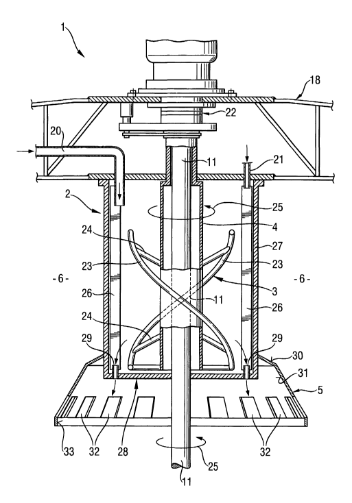
Figure 1 shows a clarification apparatus 1, inside which is a feedwell 2,
2s situated in the centre of its upper section. Inside the feedwell is located
a
slurry mixing element 3 on its shaft 4. A guiding cone 5 attached to the lower
section of the feedwell is seen only partially. Settled underflow is moved
into
a cylindrical clarification tank 6 from the edges 7 towards an underflow cone
9 situated in the lower section of the central zone 8 of the tank by means of
a
3o rake 10. A shaft 11, on which the rake is hung, travels through the mixing
element shaft 4. The power transmission of neither shaft is shown in detail.
Below rake arms 12 are displacement plates 13, and the diagram also shows
CA 02449657 2003-12-03
WO 03/000379 PCT/FI02/00537
8
that the height of the displacement plates varies depending on their distance
from the rake shaft and on the number of rake arms. A rake support structure
14 is above the rake. The central zone 8 is ring-like in shape and extends
outwards from the rake shaft a distance of 15 - 30% the length of the long
s rake arms 12. The height of the displacement plates in the central zone can
be considered constant. The rake arms are parallel with the bottom 15 of the
clarification tank, in other words sloping down towards the rake shaft and
centre of the tank. The clarification tank thus deepens towards the centre.
The clarified overflow is removed from the upper section of the tank into its
io own discharge launder 16.
Figure 2 presents the clarification apparatus of Figure 1 as seen from above.
This shows that the rake 10 is equipped in this case with two long rake arms
12 and with two shorter auxiliary arms 17 between them. The drawing shows
is one rake arm with a supporting beam 18 of the arms drive gear and the
others without. The drawing also shows the rake supporting bars 19. The
distance of the displacement plates 13 from each other is the same all along
the rake arm. As shown in the drawing, the displacement plates are at an
angle of about 30 degrees to the rake arm. The length of the displacement
Zo plates is the same all along the rake arm. The length of the displacement
plates is determined so that the tail- end of the previous plate and the front
end of the next plate overlap by 10 - 20%. The functional efficiency of the
displacement plates is also improved by the fact that the plates are at a 5 -
25 degree angle to the vertical plane i.e. they are slightly inclined towards
2s the rake shaft. As the rake rotates the underflow is displaced towards the
centre by the ploughing effect of the displacement plates. In addition, as a
result of the positioning of the displacement plates described above, the
underflow also rises a little over the displacement plates. Thanks to this
simple procedure the displacement plates do not compact the thin layer of
3o underflow below the rake, but on the contrary, keep it loose thus
preventing
the rake from getting wedged stuck.
CA 02449657 2003-12-03
WO 03/000379 PCT/FI02/00537
9
Figure 3 presents in more detail the clarification tank feedwell 2, which is
upright cylindric in shape. The slurry is fed into the well via a pipe 20, and
the
flocculant via another pipe 21. Both the slurry and the flocculant can be
injected in a gentle stream into the feedwell, because they are mixed
s together inside the well by means of a mixing element 3. The drawing shows
that the mixer shaft 4 is built as a socket so that both the mixing tank rake
shaft 11 and also the coupling flange 22 of the rake shaft fit through it. The
mixing element 3 is comprised of two tubes 23, which rotate around the shaft
at 1/3 - 2 revolutions. The tubes 23 are supported on the shaft by means of
io support elements 24. The mixing direction 25 is rising. The diameter of the
mixing element is 40 - 80% of the diameter of the feedwell.
The feedwell 2 is also equipped with baffles 26, which are located evenly on
the outer edge 27 of the feedwell. Both the slurry and the flocculant are
is preferably guided into the feedwell nearby the baffles on the front side of
the
mixing. Some of the baffles are essentially the same height as the feedwell,
but some, preferably every second one, are only 1/3 of the height of the
feedwell. All the baffles are supported to rise upwards from the base of the
feedwell 28. The baffles number from 12 - 24. Slurry discharge ports 29 are
20 located in the bottom of the feedwell always between the baffles so that
they
are in front of the baffles in regard to the rotation direction of the mixing
element. According to the feedwell of this invention, the flocculant is mixed
into the slurry quickly, but when the residence time of the slurry in the
feedwell is regulated between 3 - 15 minutes, the slurry is flocculated well
2s before it is guided onwards.
Attached to the bottom of the feedwell is a guiding cone 5, which opens
downward, and the feedwell discharge ports open into the inside of the
guiding cone. The guiding cone is comprised of one or several conical
3o surfaces and is preferably, although not necessarily, open inside. Figure 3
shows two conical surfaces, of which the upper one 30 opens downwards at
a 20 - 45 degree angle (from the horizontal). The upper conical surface is
CA 02449657 2003-12-03
WO 03/000379 PCT/FI02/00537
tightly fixed to the lower conical surface 31, which opens downwards at a 45
- 75 degree angle (from the horizontal). Located in the lower section of the
guiding cone are the slurry guide ports 32. The ports number for example
between 16 - 32 and the outflow of slurry from them can be adjusted within
s the range of 0.05 - 0.2 m/s. The lower edge 33 of the guiding cone is whole
and preferably vertical. The purpose of the guiding cone is to prevent the
slurry being fed into the clarification tank from flowing strongly towards the
surface of the underflow layer, which would jeopardise the clarity of the
overflow solution. The guiding cone can be dimensioned so that the diameter
io of its lower edge is 1.3 - 2 times larger than the diameter of the
feedwell.
When the guiding cone is formed of several conical surfaces, the steepest
conical surface preferably accounts for 55 - 70% of the total height of the
whole guiding cone.
is The invention is described further by means of the following examples.
Example 1
It was desired to obtain an even displacement of underflow in an industrial
scale thickener developed from the perimeter of the cylindrical tank towards
2o the underflow well in the centre. The diameter of the thickener was 27 m
and
the amount of underflow to be moved to the well was 40 m3/h. An operating
speed of 0.075 rpm was chosen for the rake system. The attached Table 1
shows how the height of the displacement plates increases first from the
outer perimeter up to the auxiliary rake arms, where the height of the plates
2s decreases, because their number is doubled. After the minimum point at the
tip of the auxiliary rake arms, the height of the displacement plates again
increases towards the centre. The last displacement plates, those closest to
the centre are the same height as each other, so the outward raking
pressure compacts the underflow even more.
CA 02449657 2003-12-03
WO 03/000379 PCT/FI02/00537
11
Table 1
Numbering Height of Displacement
of displacementcapacity of plates
displacement plates on
plates mm same circumference
from m'Ih
edge of
tank
towards
centre
Main rakeAuxiliary
arms rake arms
1,2 120 43.6
2,3 125 43.6
3,4 130 43.8
4,5 135 43.7
5,6 140 43.3
6,7 148 43.8
7,g 156 44.1
8,9 164 44.2
9,10 172 44.0
10,11 180 43.7
11,12 190 43.7
12,13 200 43.2
13,14 210 42.6
14,15 220 41.7
15,16 1,2 130 45.8
16,17 2,3 145 47.2
17,18 3,4 160 47.8
18,19 4,5 175 47.6
19,20 5,6 190 46.6
20,21 6,7 205 44.8
21,22 7,8 220 42.2
22,23 8,9 220 36.3
23,24 9,10 220 30.5
24,25 10,11 220 24.5
25,26 11,12 220 18.7
26,27 12,13 ~ 220 17.4
Example 2
A settling test showed that the slurry is distributed evenly in a thickener
s according to the invention. The slurry used in the tests was an industrial-
scale thickener underflow, which had been obtained by neutralising the
waters containing iron(III), chrome(III) and nickel(II) and sulphate generated
in refined steel pickling. 52% of the solids in the slurry were gypsum and the
rest metal hydroxides. The diameter of the test thickener was 1100 mm and
CA 02449657 2003-12-03
WO 03/000379 PCT/FI02/00537
12
the effective depth of the cylinder section 340 mm. The conical bottom
inclined at an angle of 9.5° towards the centre. The rake was in
principle
according to that described in example 1. The diameter of the feedwell of the
thickener was 172 mm and the effective depth 315 mm. The baffles and
s guiding cone were as described in the preamble. The feedwell mixer was a
helix-type i.e. including two tubes around the shaft rising one revolution in
the mixing direction, and at a constant distance from the shaft. The diameter
of the mixer was 110 mm and the depth 252 mm.
to The underflow previously settled in the settling test was pumped back into
circulation via the thickener feedwell. Water was also fed into the feedwell
in
the proportion of three parts to one part underflow. Water separated in the
thickener was removed as thickener overflow. The feed of underflow and
water was increased in proportion and then lowered in the same ratio to
is determine the separation capacity and separation efficiency of the
thickener.
At first a flocculant was not used, so that the performance characteristic of
the thickener was largely dependent on how evenly the slurry flowed out of
the feedwell when it was first mixed. In the test, the speed of revolution of
the
mixer was 127 rpm and that of the rake 0.4 rpm. In the final stages of the
test
2o the clear separated water layer developed as follows:
Table 2
Time Water feed Underflow Water layer
feed
min I/h I/h Mm
00 142 45 119
15 144 45 94
114 131 36 87
170 131 35 75
195 101 35 82
According to the results described above, the maximum feed of the test
2s thickener can be determined as about 120 I/h water and 40 I/h underflow.
CA 02449657 2003-12-03
WO 03/000379 PCT/FI02/00537
13
The input flows can be raised surprisingly high, when taking into account the
settling properties and the fact that no flocculant was used in the test. The
water layer that separated out was completely clear, which also indicates
that the mixer used in the feedwell evens out the thickener feed. The
s conventional thickener, from whence the underflow used in the test came,
was not able to achieve the same performance, since the separated overflow
remained cloudy.
Example 3
to The test in example 2 was carried out using the flocculant Fennopol A305,
which was dosed as a 0.5 g/I-solution of 136 mg/kg solids. The overflow
layer was in the order of 100 mm and completely clear, when the feed was
360 I/h water and 120 I/h underflow. The feedwell mixer was thus able to mix
the water, underflow and flocculant homogeneously and distribute it evenly
is into the slurry layer of the thickener.