Note: Descriptions are shown in the official language in which they were submitted.
CA 02449719 2003-12-01
WO 02/096784 PCT/CA02/00794
LINEAR CONVEYOR SYSTEM
2
3 BACKGROUND OF THE INVENTION
4
1. FIELD OF THE INVENTION
6 [0001] The present invention relates to a conveyor apparatus. More
specifically, the
7 invention relates to a conveyor system for linearly transporting articles
such as microtiter
8 plates.
9
2. DESCRIPTION OF THE PRIOR ART
11 [0002] Conveyors are well known for moving objects between different
locations and
12 typically include an endless belt or chain moving uni-directionally between
different stations.
13 The advent of robotic systems has increased the dependency on conveyor
systems to move
14 work pieces accurately between different workstations, as human
intervention is no longer
available to ensure accurate positioning or to make real time adjustments to
the location of
16 the work piece.
17 [0003] Where registration of the work piece on a conveyor is necessary, it
is known to
18 provide stops alongside the belt conveyor that provide an abutment for the
work piece and
19 inhibit relative movement between the work piece and the conveyor belt.
Such an
arrangement is shown in U.S. Patent 6,095,316 to Redden in which a pair of
endless chains or
21 belts are located on opposite sides of a slide way and engage the rear edge
of the work piece.
22 Such an arrangement, however, involves a large number of mechanical parts
and requires an
23 accurate registration between the chains to obtain correct alignment of the
work piece and the
24 conveyor.
[0004] One particular area in which the use of robotics has been widely
deployed is in the
26 pharmaceutical research laboratory where biological samples, usually
contained on microtiter
27 plates, are to be moved between different test equipment without human
intervention. In
28 such an environment accurate positioning of the plates is critical and at
the same time, the
29 conveyor must be reliable and have as few moving parts as possible to avoid
undue
complexity.
31 [0005] It is therefore an object of the present invention to provide a
conveyor in which
32 the above disadvantages are obviated or mitigated.
-1-
SUBSTITUTE SHEET (RULE 26)
CA 02449719 2003-12-01
WO 02/096784 PCT/CA02/00794
1
2 SUMMARY OF THE INVENTION
3 [0006] According, therefore, to one aspect of the present invention, there
is provided a
4 conveyor for moving at least one article along a predetermined path the
conveyor having an
endless belt entrained about a pair of supports spaced apart along the path. A
support surface
6 on the belt receives the article, and a drive mechanism moves the belt
relative to the supports
7 along the path. The support surface has a pair of abutments to inhibit
relative movement
8 between the article and the belt along the predetermined path.
9 [0007] According to a further aspect of the invention, there is provided a
conveyor
system to move an article along a predetermined path. The system comprises a
pair of
11 workstations and a conveyor extending along the predetermined path between
the pair of
12 workstations. The conveyor has an endless belt entrained about a pair of
supports spaced
13 apart along the path with a support surface on the belt to receive the
article. A drive
14 mechanism moves the belt relative to the supports along the path. The
support surface having
a pair of abutments positioned on the belt to engage oppositely directed
surfaces on the article
16 and inhibit relative niovement between the belt and the article along the
path.
17 [0008] In another embodiment, the invention provides a conveyor system for
moving a
18 microtiter plate along a predetermined path between one or more
workstations, the system
19 comprising:
- an conveyor belt extending between a drive pulley and an idler pulley, the
belt
21 including an upper, plate supporting surface a lower pulley engaging
surface;
22 - a support structure for the belt and the pulleys; and
23 - a drive mechanism for driving the drive pulley;
24 wherein the plate supporting surface of the conveyor belt includes a pair
of abutments
for receiving the microtiter plate and for maintaining the plate in position
as the belt moves
26 the plate along the predetermined path.
27
28 BRIEF DESCRIPTION OF THE DRAWINGS
29 [0009] An embodiment of the invention will now be described by way of
example only
with reference to accompanying drawings in which:
31 [0010] Figure 1 is a schematic representation of a conveyor system;
-2-
=.--
SUBSTITUTE SHEET (RULE 26)
CA 02449719 2003-12-01
WO 02/096784 PCT/CA02/00794
1 [0011] Figure 2 is a perspective view of a portion of the conveyor system
shown in
2 Figure 1;
3 [0012] Figure 3 is a longitudinal cross sectional view of the system of
Figure 2;
4 [0013] Figure 4 is a transverse cross sectional view of the system of Figure
2;
[0014] Figure 5 is a plan view of one embodiment of a belt for use with the
conveyor
6 system of the present invention;
7 [0015] Figure 6 is a side elevation of the belt of Figure 5.
8 [0016] Figure 7 is a plan view of another embodiment of a belt for use with
the conveyor
9 system of the present invention;
[0017] Figure 8 is a side elevation of the belt of Figure 7;
11 [0018] Figure 9 is a side elevation of a portion of the belt of Figure 7;
12 [0019] Figure 10 is a perspective view of a conveyor system according to
one
13 embodiment of the invention;
14 [0020] Figure 11 is a perspective view of a portion of the system of Figure
10 illustrating
the drive mechanism;
16 [0021] Figure 12 is a perspective view of a mid portion of the system of
Figure 10; and,
17 [0022] Figure 13 is a perspective view of a portion of the system of Figure
10 illustrating
18 the idler end of the system.
19
DESCRIPTION OF THE PREFERRED EMBODIMENTS
21 [0023] Referring therefore to Figure 1, a conveyor system 10 includes a
conveyor 12
22 extending between workstations 14, 16, and 18. The conveyor 12 moves
articles 20 along the
23 predetermined path indicated by the arrow "P" between respective ones of
the workstations
24 14, 16 and 18 under the control of a controller 22.
[0024] Each of the workstations 14, 16 and 18 has a pair of robotic arms 24,
26 controlled
26 through the controller 22 to perform specific operations on the articles
20. Each of the arms
27 24, 26 is independently controlled for operation on the articles 20 and it
will be appreciated
28 that the nature of the operations and the nature of the arms 24, 26 will
depend upon the
29 articles to be conveyed. The details of the arms 24, 26 and their specific
operations are well
known in the art and need not be further described at this time.
31 [0025] As can best be seen in Figure 2, the conveyor 12 includes an endless
belt 30
32 entrained about a pair of support rollers 32, 34. The rollers 32, 34 are
rotatably mounted on
-3-
SUBSTITUTE SHEET (RULE 26)
CA 02449719 2003-12-01
WO 02/096784 PCT/CA02/00794
I spindles 36, 38 respectively and are maintained in spaced relationship by
side frames 49that
2 extend along the length of the conveyor 12. The side frames 40 are supported
on legs 42 to
3 maintain the conveyor 12 at the required height and cross members 44
maintain the side
4 frames 40 in spaced relationship. The belt 30 is supported between the
rollers 32 on a slide
46, which is supported on the cross members 44. The slide 46 may be made of a
suitable low
6 friction material such as a high-density polyethylene that allows the belt
30 to slide smoothly
7 between the rollers. Side rails 48 are secured to the slide 46 and project
above the belt 12 to
8 locate articles 20 laterally relative to the belt.
9 [0026] A servo motor 50 is secured to the spindle 36 associated with the
roller 32 and
rotates the roller 32 to impart linear motion to the belt 30. The servo motor
50 is reversible
11 and is controlled from the controller 22 to move the belt 30 in either
direction along the path
12 P. The servo motor 50 will be controlled from the controller 22 using
standard closed loop
13 control techniques implemented by the controller so that the position of a
particular location
14 on the belt 30 is known at any given time. Such controllers and servo
motors are readily
available, such as those available from Kollmorgen of Radford, VA..
16 [0027] The endless belt 30 has oppositely directed surfaces, namely a drive
surface 52
17 and support surface 54, as shown in Figure 4. The drive surface 52
cooperates with the
18 rollers 32, 34 and slide 46, whereas the support surface 54 supports the
articles 20. Ribs 56
19 are provided on the support surface 54 at spaced intervals and extend
laterally across the belt
30 in a direction normal to the predetermined path P. The ribs 56 in one
preferred
21 embodiment are of square cross section having side faces 58 and an upper
face 60. The ribs
22 56 are arranged in pairs along the length of the belt 30 with opposed side
faces 58 of each
23 pair spaced apart a distance slightly greater than the overall length L of
the article 20. The
24 spacing between the opposed side faces 58 provides a snug fit for the
article 20 without
unduly hampering the placement and removal of the article 20 on the belt 30.
The side faces
26 58 provide abutments for the article 20 and thereby inhibit relative
movement between the
27 belt 30 and the article 20 along the path P.
28 [0028] In operation, the servo motor 50 moves the belt 30 such that a pair
of ribs are
29 positioned at one of the workstations 14, 16, 18 at which an article is to
be placed in the belt
30. The arm 24 places the article on the belt so that it is received between
the ribs 56 and
31 thereby secured against unintentional movement. At the same time, articles
located at other
32 workstations 14, 16, 18 may operated upon by the respective anns 24, 26
either by removal
-4-
SUBSTITUTE SHEET (RULE 26)
CA 02449719 2003-12-01
WO 02/096784 PCT/CA02/00794
1 and replacement with an alternate article or a specific operation performed
by the arm on that
2 article.
3 [0029] After completion of the operation by the arms 24, 26 at each of the
work station
4 14, 16, 18, the servo motor 50 under the control of the controller 22 drives
the belt 30 to
position the article adjacent another of the arms 24, 26. This may be another
arm at the same
6 workstation or may be moved to a different workstation for further operation
to be
7 performed. Again, once the set of operations at each workstation is
completed, the controller
8 22 operates through the servo motor to move the article 20 to another
position.
9 [0030] Movement of the belt 30 may be in either direction by virtue of the
reversible
nature of the servo motor 50 with the location of the articles 20 on the belt
secured in either
11 direction by the abutments provided by the ribs 56. The side rails 48
prevent lateral
12 displacement so that the article 20 is securely located on the belt 30. The
article 20 may thus
13 be moved between workstations in either direction permitting operations to
be performed at
14 each workstation by each of the robotic arms independently of the other
operations. Upon
completion of the operations on the article, it is moved to an arm 24, 26 for
removal from the
16 belt whilst a further article is placed on the belt by another one of the
arms.
17 [0031] A typical application for the conveyor system 10 is found in a
pharmaceutical
18 research laboratory where the article 20 may be a microtiter plate with the
operations
19 performed at the robotic arm the placement and removal of the plates from
the belt and test
operations performed on the contents of the plate. In such an application, the
plates typically
21 have dimensions of length 5.030" by 3.365" and a depth of 0.565". With such
an
22 embodiment, it has been found that the appropriate spacing between the side
faces 58 of the
23 ribs 56 has a clearance of 0.040" on the overall length to facilitate
placement of the articles
24 20.
[0032] In the preferred embodiment the belt 30 is a flexible urethane belt and
the ribs 56
26 are urethane blocks with a cross section of 0.100" x 2.800". Clearly,
custom belts maybe
27 provided from a suitable flexible structure such as a nylon reinforced
polymer with the ribs
28 56 molded integrally with the support surface 54. The ribs may be of other
suitable forms,
29 for example a series of buttons or ledges rather than a continuous rib if
preferred.
[0033] As shown, the ribs are arranged as discrete pairs along the length of
the support
31 surface. In an alternative embodiment where the desired spacing of the
articles permits, each
-5-
SUBSTITUTE SHEET (RULE 26)
CA 02449719 2003-12-01
WO 02/096784 PCT/CA02/00794
1 of the ribs may separate adjacent articles so that a continuous array of
articles is provided.
2 Each of the side faces 58 then acts as an abutment.
3 [0034] It will be noted that the conveyor 12 provides a simple but effective
mechanism
4 for moving articles 20 in either direction along the path between
workstations. Joint operation
of the robotic arms is facilitated and the use of the reversible servo motor
avoids complicated
6 mechanism for moving the belt.
7 [0035] Figures 5 and 6 illustrate details of the belt of the invention
according to a
8 preferred embodiment and wherein similar reference numerals are used as with
the previously
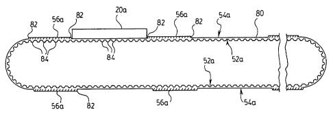
9 described figures but with the letter "a" added for clarity. As shown, the
belt 30a includes a
drive surface 52a and a support surface 54a. The ribs 56a according to the
illustrated
11 embodiment, also extend laterally across the width of the belt, on the
support surface 54a
12 thereof, as described above. However, in this embodiment, the ribs 56a also
partly extend
13 along the longitudinal direction of the belt, thereby resulting in ribs 56a
that assume a pad-
14 like appearance on the belt 30a. The spaces between the ribs 56a provide
for "nests" 80 for
receiving the articles 20a, as described before. As indicated above, such
articles 20a may
16 comprise, for example, microtiter plates as illustrated.
17 [0036] The belt 30a illustrated in Figures 5 and 6 allow for the articles
20a to be placed
18 on the belt 30a such that they are spaced apart by a greater distance than
in the embodiment
19 described previously. It will be understood by persons skilled in the art
that the size of the
ribs 56 or 56a will vary on the desired spacing of the articles 20a being
transported and, as
21 such, any size of same may be used.
22 [0037] As also illustrated in Figure 6, the side faces of the ribs are
preferably provided
23 with chamfered edges 82, which facilitates the positioning of the article
20a into the "nests"
24 80 on the belt 30a.
[0038] The belt 30a illustrated in Figure 6 also preferably includes cogs 84
on the drive
26 surface 52a that cooperate with complementary cogs on the rollers (not
shown).
27 [0039] Another embodiment of the conveyor belt of the invention is
illustrated in Figures
28 7 and 8, wherein similar reference numerals as above are used to identify
similar elements,
29 but with the letter "b" used for clarity. In the embodiment shown, the ribs
56b are more
narrow than that of the previously described embodiment and appear as cleats
on the support
31 surface 54b of the belt 30b. However, a nest, 80b, is still provided
between a pair of ribs for
32 receiving a plate to be transported. In this embodiment, an example of
dimensions would
-6-
SUBSTITUTE SHEET (RULE 26)
CA 02449719 2003-12-01
WO 02/096784 PCT/CA02/00794
1 include a nest length of 5.07", which corresponds to the length of a
standard microtiter plate
2 but with an allowance for a non-frictional fit.
3 [0040] Figures 7 and 8 also illustrate the provision of a homing cleat or
rib, 90, which
4 serves to register the position of the nests as the belt is moved. Such
homing cleats are
known in the art and would comprise a metal body that can be registered with a
magnetic
6 means on the conveyor device. The homing cleat is also used to zero the belt
upon start-up of
7 the conveyor device.
8 [0041] Figure 9 illustrates an detail of the ribs or cleats 56b and the cogs
84b of the belt
9 30b shown in Figures 7 and 8. As can be seen, the cleats 56b include a
chamfered upper edge
82b on the side of the cleat facing the nest. In this manner, positioning of
the plate in the nest
11 is assisted with the adjacent chamfered edges 82b being used to guide the
plate into the nest.
12 In a preferred embodiment, the chamfer is 45 .
13 [0042] It will be understood that the ribs or cleats 56b of the belt 30b
would preferably be
14 positioned on the belt 30b in reference to the size and pitch of the cogs
84b of the drive
surface 52b of the belt. That is, the cleats 56b will generally be offset from
adjacent cogs 84b
16 by a distance D as shown in Figure 9. For example, in one embodiment, both
the cleats 56b
17 and the cogs 84b are 0.25" wide (taken along the longitudinal direction of
the belt), and the
18 cleats 56b are spaced 0.12" from the cogs (that is, for this example, D
would 0.12"). It will
19 be understood that the above dimensions will vary depending upon the pitch
and size of the
cogs and cleats and that such positioning will be apparent to persons skilled
in the art.
21 [0043] Figure 10 illustrates an example of the conveyor device of the
present invention
22 when used in an apparatus 100. The conveyor belt of the invention is shown
at 102. The
23 apparatus includes a loading end 104 and a discharge end 106. The apparatus
comprises the
24 belt 102 and a frame 108, which supports the belt and a drive mechanism for
same. On each
side of the belt 102, are provided a plurality of work stations 110. Each
workstation
26 essentially comprises a table that is positioned along the side of the belt
and on which can be
27 positioned any desired robotics or other needed equipment. Although the
apparatus of Figure
28 10 indicates an embodiment where workstations are located on both sides of
the belt 102, it
29 will be appreciated that such stations can also only be provided on one
side of the belt and
that the number and positioning of such workstations will vary depending upon
the need. For
31 example, where a space is needed for access, one of the stations can be
removed. As will be
-7-
SUBSTITUTE SHEET (RULE 26)
CA 02449719 2003-12-01
WO 02/096784 PCT/CA02/00794
1 understood, such modularity allows the system and apparatus of the invention
to be used in
2 any number of ways.
3 [0044] As shown in Figure 10, the entire apparatus may be supported on legs
111 so as to
4 enable the height of the belt and workstations to be adjusted as needed. The
embodiment of
Figure 10 also illustrates an optional chute 112 for diverting any plates that
are to be
6 discarded off the conveyor. In another embodiment, the chute 112 can be
replaced with a
7 plate catcher. A plate catcher is shown in Figure 10 as element 114. As will
be understood,
8 the purpose of the catcher 114 is to capture any plates that are ejected
from the belt.
9 [0045] Figures 11 to 13 illustrate details of a preferred support structure
and drive
mechanism for the conveyor belt of the invention. The components illustrated
in these
11 figures would be, for example, that used in the apparatus of Figure 10.
12 [0046] Figure 11 illustrates the drive section of conveyor system, which
includes a drive
13 motor contained within a housing 120. A drive arm projecting from the
housing 120 is
14 provided with a drive pulley 122. As shown, the drive pulley 122 comprises
a generally
cylindrical body with a plurality of ribs extending longitudinally along the
body and
16 generally parallel with the longitudinal axis thereof. It will be
understood that the ribs are
17 designed to engage the cogs provided on the belt (not shown) of the
conveyor. In this
18 manner, when the drive motor is actuated, the rotation of the drive pulley
122 serves to move
19 the belt as described above.
[0047] Figure 11 also illustrates the support 124 upon which the conveyor belt
rests. In
21 the preferred embodiment, since the belt slides over the support 124, the
support will be made
22 of a material that avoids excessive friction. In the preferred embodiment,
the support
23 structure for the belt also includes a pair of side walls 126 and 128 that
extend along the
24 length of the conveyor belt. In a more preferred embodiment, the side walls
126 and 128
extend above the support 124 and over the belt (not shown). In this manner,
the top edges of
26 the side walls 126 and 128 serve as lateral positioning guides for the
plates being transported
27 by the belt and also serve to restrict and lateral movement of the plates
off the belt. As
28 described above, ribs or cleats on the belt serve to restrict longitudinal
movement of the
29 plates. In this manner, the plates are maintained on the belt and in the
desired position.
[0048] Figure 12 illustrates the mid portion of the conveyor support
structure.
31 [0049] Figure 13 illustrates the non-driving end, or idler end of the
conveyor system. In
32 this case, a preferably freely rotating idler pulley 130 is provided on an
axle (not shown).
-8-
SUBSTITUTE SHEET (RULE 26)
CA 02449719 2003-12-01
WO 02/096784 PCT/CA02/00794
1 The conveyor belt of the system is wrapped around the idler pulley to
complete the structure.
2 As shown, the idler pulley 130, like the drive pulley 122 described above,
comprises a
3 generally cylindrical body and is preferably provided with a plurality of
longitudinally
4 extending ribs for engaging the cogs on the conveyor belt. As will be
appreciated, the idler
pulley may also simply have a smooth exterior surface.
6 [0050] Although the invention has been described with reference to certain
specific
7 embodiments, various modifications thereof will be apparent to those skilled
in the art
8 without departing from the spirit and scope of the invention as outlined in
the claims
9 appended hereto.
11
-9-
SUBSTITUTE SHEET (RULE 26)