Note: Descriptions are shown in the official language in which they were submitted.
CA 02449828 2003-12-03
WO 03/003975 PCT/US02/18472
TITLE OF THE INVENTION
DETECTION AND THERAPY OF VULNERABLE PLAQUE WITH
PHOTODYNAMIC COMPOUNDS
RELATED APPLICATIONS/PATENTS & INCORPORATION BY REFERENCE
This application claims priority to U.S. Provisional Application No.
60/295,627,
filed June 4, 2001, and U.S. Provisional Application No. 60/365,673, filed
March 15,
2002, the contents of which are expressly incorporated herein by reference.
Each of the applications and patents cited in this text, as well as each
document
or reference cited in each of the applications and patents (including during
the
prosecution of each issued patent; "application cited documents"), and each of
the PCT
and foreign applications or patents corresponding to and/or claiming priority
from any
of these applications and patents, and each of the documents cited or
referenced in each
of the application cited documents, are hereby expressly incorporated herein
by
reference. More generally, documents or references are cited in this text,
either in a
Reference List before the claims, or in the text itself; and, each of these
documents or
references ("herein-cited references"), as well as each document or reference
cited in
each of the herein-cited references (including any manufacturer's
specifications,
instructions, etc.), is hereby expressly incorporated herein by reference.
STATEMENT OF RIGHTS TO INVENTIONS MADE UNDER FEDERALLY
SPONSORED RESEARCH
This work was supported by the government, in part, by a grant from the United
States Department of Defense, Grant No. 17-99-2-9001. The govenunent may have
certain rights to this invention.
FIELD OF THE INVENTION
The present invention relates to methods for detection and therapy of thin-
capped fibro-atheroma ("vulnerable plaque") using selectively targeted
photodynamic
compounds. The present invention further relates to devices for use in the
detection and
therapy of vulnerable plaque. Other aspects of the invention are described in
or are
obvious from the following disclosure (and within the ambit of the invention).
CA 02449828 2003-12-03
WO 03/003975 PCT/US02/18472
2
BACKGROUND OF THE INVENTION
Cardiovascular disease remains the leading cause of morbidity and mortality in
the United States. A chief contributor to the pathology of the disease is the
formation of
atherosclerotic or "atheromatous" plaques in the coronary arteries (Farb et
al. (1995)
Circulation 92:1701-1709). Yet, therapies designed to ameliorate the occlusive
effects
of atheromatous plaques on coronary blood flow, such as coronary artery bypass
surgery and percutaneous transluminal coronary angioplasty, do not prevent or
reduce
the incidence of acute coronary syndrome. Acute coronary syndrome covers a
group of
sudden-onset coronary diseases, including unstable angina, acute myocardial
infarction
and sudden cardiac death. The causative agent of acute coronary syndrome is
fissure,
erosion or rupture of a specific kind of atheromatous plaque known as a
"vulnerable
plaque." Vulnerable plaques are responsible for the majority of heart attacks,
strokes,
and cases of sudden death.
Post-mortem evidence suggests that vulnerable plaque rupture occurs in areas
of
the coronary arteries that are less than about 50% stenosed. Thus, angioplasty
and
bypass procedures, which are carried out on severely stenosed arteries, rarely
remove
vulnerable plaques or reduce the incidence of acute coronary syndrome (Plutzky
(1999)
Am J Cardiol 84:15J-20J). Even with currently available therapeutic
approaches, such
as lipid lowering, angioplasty and bypass, an unacceptably high incidence of
acute
coronary syndrome remains (Sacks et al. (2000) Circulation 102:1893-1900).
Atheromatous plaques characteristically comprise a fibrous cap surrounding a
central core of extracellular lipids and debris located in the central portion
of the
thickened vessel intima, which is known as the "atheroma." On the luminal side
of the
lipid core, the fibrous cap is comprised mainly of connective tissues,
typically a dense,
fibrous, extracellular matrix made up of collagens, elastins, proteoglycans
and other
extracellular matrix materials. At the edges of the fibrous cap overlying the
lipid core is
the shoulder region, enriched with macrophages. The macrophages continually
phagocytose oxidized LDL through scavenger receptors, which have a high ligand
specificity for oxidized LDL. Continuous phagocytosis results in the formation
of foam
cells, a hallmark of the atherosclerotic plaque (Parthasarathy et al. (1992)
Annu Rev
Med 43:219-225). Foam cells, together with the binding of extracellular lipids
to
CA 02449828 2003-12-03
WO 03/003975 PCT/US02/18472
3
collagen fibers and proteoglycans, play an important role in the formation and
growth of
the lipid-rich atheroma.
Histopathologic examination of atheromatous plaques has revealed substantial
variations in the thickness of fibrous caps, the size of the atheromas, the
extent of
dystrophic calcification and the relative contribution of major cell types
(van der Wal et
al. (1994) Coron Artery Dis 5:463-469). Resident cells present in atheromatous
plaques
include a significant population of inflammatory cells, such as
monocyteslmacrophages
and T lymphocytes. The emigration of monocytes into the arterial wall, and
their
subsequent differentiation into macrophages and ultimately foam cells, remains
one of
the earliest steps in plaque formation. Once there, these cells play a
critical role in
secreting substances that further contribute to atherosclerosis.
A vulnerable plaque is structurally and functionally distinguishable from a
stable
atheromatous plaque. For example, several histologic features distinguish a
vulnerable
plaque from a stable atheromatous plaque. A vulnerable plaque is characterized
by an
abundance of inflammatory cells (e.g., macrophages and/or T cells), a large
lipid pool,
and a thin fibrous cap. An atheromatous plaque refers to a wide range of
coronary
lesions, from subtle collections of lipid, to obstructive coronary lesions
that cause
angina.
In contrast to vulnerable plaques, the vast majority of atheromatous plaques
lay
silent. Only the raze atheromatous lesion causes heart attacks or strokes.
Pathologic
studies have provided a further understanding of why vulnerable plaques have a
higher
propensity for rupture than other atheromatous plaques. The thickness and
integrity of
the fibrous cap overlying the lipid-rich core is a principal factor in the
stability of the
plaque. Vulnerable plaques prone to rupture can be characterized as having
thinner
fibrous areas, increased numbers of inflammatory cells (e.g., macxophages and
T cells),
and a relative paucity of vascular smooth muscle cells. Vascular smooth muscle
cells
are the major source of extra cellular matrix production, and therefore, the
absence of
vascular smooth muscle cells from a vulnerable plaque contributes to the lack
of density
in its fibrous cap.
While the fibrous tissue within the cap provides structural integrity to the
plaque, the interior of the atheroma is soft, weak and highly thrombogenic. It
is rich in
CA 02449828 2003-12-03
WO 03/003975 PCT/US02/18472
4
extracellular lipids and substantially devoid of living cells, but bordered by
a rim of
lipid-laden macrophages (van der Wal et al. (1999) Cardiovasc Res 41:334-344).
The
lipid core is a highly thrombogenic composition, rich in tissue factor, which
is one of
the most potent procoagulants known. The lesional macrophages and foam cells
produce a variety of procoagulant substances, including tissue factor. The
fibrous cap is
the only barrier separating the circulation from the lipid core and its
powerful
coagulation system designed to generate thrombus. Essentially, the rapid
release of
procoagulants into the blood stream at the site of rupture forms an occlusive
clot,
inducing acute coronary syndrome. Thus, the thinner the fibrous cap, the
greater the
instability of the thrombogenic lipid core and the greater the propensity for
rupture and
thrombosis.
Several factors can contribute to the weakened state of the fibrous cap. In
particular, inhibition of extracellular matrix production or degradation of
extracellular
matrix components adversely impacts the structural composition of the fibrous
cap.
Macrophages and T lymphocytes have been identified as the dominant cell types
at the
site of plaque rupture or superficial erosion, and each of these inflammatory
cells
contributes to the inhibitory and/or degradative pathways. Accelerated
degradation of
collagen and other matrix components is carried out by macrophage proteases,
such as
matrix metalloproteinases ("MMPs"), which are secreted at the site of the
plaque.
MMPs constitute an extensive family of enzymes, including interstitial
collagenase
(e.g., MMP- I), gelatinases (e.g., MMP-2, MMP-9), and stromelysin (e.g., MMP-
3).
Stromelysins can activate other members of the MMP family, causing degradation
among many matrix constituents. The presence of T cells in the plaque can
further
contribute to weakening of the fibrous cap. Activated T cells produce and
secrete
interferon-y, a potent inhibitor of collagen synthesis. Thus, the T
lymphocytes represent
a potentially large source of interferon-y that can negatively regulate matrix
production.
Plaque rupture sites are further characterized by expression of major
histocompatibility
complex genes, (e.g., human lymphocyte antigen-DR on inflammatory cells and
adjacent smooth muscle cells), indicating an active inflammatory reaction that
also
weakens the fibrous cap.
CA 02449828 2003-12-03
WO 03/003975 PCT/US02/18472
Present methods of plaque detection, several of which are discussed herein,
are
inadequate for the identification of vulnerable plaques. Common methods of
plaque
detection include angiography and angioscopy. Except in rare circumstances
angiography gives almost no information about characteristics of plaque
components.
Angiography is only sensitive enough to detect hemodynamically significant
lesions
(>70% stenosis), which account for approximately 33% of acute coronary
syndrome
cases. Angioscopy is a technique based on fiber-optic transmission of visible
light that
provides a small field of view with relatively low resolution for
visualization of interior
surfaces of plaque and thrombus. Because angioscopic visualization is limited
to the
surface of the plaque, it is insufficient for use in detecting vulnerable
plaques.
Several methods are being investigated for their ability to identify
vulnerable
plaques. However, none has proven to be sufficiently sensitive. One such
method,
intravascular ultrasound ("IVUS") uses miniaturized crystals incorporated at
catheter
tips and provides real-time, cross-sectional and longitudinal, high-resolution
images of
the arterial wall with three-dimensional reconstruction capabilities. IVUS can
detect
thin caps and distinguish regions of intermediate density (e.g., intima that
is rich in
smooth muscle cells and fibrous tissue) from echolucent regions, but current
technology
does not determine which echolucent regions are composed of cholesterol pools
rather
than thrombosis, hemorrhage, or some combination thereof. Moreover, the
spatial
resolution (i.e., approximately 200 mm) does not distinguish the moderately
thinned cap
from the high risk cap (i.e., approximately 25-75 mm) and large dense calcium
deposits
produce acoustic echoes which "shadow" so that deeper plaque is not imaged.
Tntravascular thermography is based on the premise that plaques with dense
macrophage i~ltration give off more heat than non-inflamed plaque (Casscells
et al.
(1996) Lancet. 347:1447-1451). The temperature of the plaque is inversely
correlated
to cap thickness. However, thermography may not provide information about
eroded
but non-inflamed vulnerable lesions.
Optical coherence tomography ("OCT") measures the intensity of reflected near-
infrared light from tissue. It provides images with high resolution that is
approximately
to 20 times higher than that of IVUS resolution. OCT is primarily used for
assessment of atherosclerotic plaque morphology. However, long image
acquisition
CA 02449828 2003-12-03
WO 03/003975 PCT/US02/18472
6
time, high costs, limited penetration and a lack of physiologic data render
this approach
undesirable for detection of vulnerable plaques.
Raman spectroscopy utilizes Raman effect: a basic principle in photonic
spectroscopy named after its inventor. Raman effect arises when an incident
light
excites molecules in a sample, which subsequently scatter the light. While
most of this
scattered light is at the same wavelength as the incident light, some is
scattered at a
different wavelength. This shift in the wavelength of the scattered light is
called Raman
shift. The amount of the wavelength shift and intensity depends on the size,
shape, and
strength of the molecule. Each molecule has its own distinct "fingerprint"
Raman shift.
Raman spectroscopy is a very sensitive technique and is capable of reporting
an
accurate measurement of chemical compounds. Conceivably, the ratio of lipid to
proteins, such as collagen and elastin, might help detect vulnerable plaques
with large
lipid pools. However, it is unlikely that vulnerable plaques will be reliably
differentiated from stable plaques based solely on this ratio.
Photodynamic therapy ("PDT") employs photoactivatable compounds known as
photosensitizers to selectively target and destroy cells. Therapy involves
delivering
visible light of the appropriate wavelength to excite the photosensitizer
molecule to the
excited singlet state. This excited state can then undergo intersystem
crossing to the
slightly lower energy triplet state, which can then react further by one or
both of two
pathways, known as Type I and Type II photoprocesses (Ochsner (1997) J
Photochem
Photobiol B 39:1-18). The Type I pathway involves electron transfer reactions
from the
photosensitizer triplet to produce radical ions which can then react with
oxygen to
produce cytotoxic species such as superoxide, hydroxyl and lipid derived
radicals. The
Type II pathway involves energy transfer from the photosensitizer triplet to
ground state
molecular oxygen (triplet) to produce the excited state singlet oxygen, which
can then
oxidize many biological molecules such as proteins, nucleic acids and lipids,
and lead to
cytotoxicity.
Photodynamic therapy (PDT) has recently gained regulatory approval in the
United States for treatment of esophageal cancer and in other countries for
several other
types of cancers (Dougherty et al. (1998) J Natl Cancer Inst 90:889-905).
Certain
photosensitizers accumulate preferentially in malignant tissues (Hamblin &
Newman
CA 02449828 2003-12-03
WO 03/003975 PCT/US02/18472
7
(1994) J Photochem Photobiol B 23:3-8), creating the advantage of dual
selectivity: not
only is the photosensitizer ideally specific for the target tissue, but the
light can also be
accurately delivered to the target tissue, thereby limiting the area within
which the toxic
effects of the photosensitizer are released.
Photodynamic therapy has been applied in cardiovascular medicine for two
broad indications: treatment of atherosclerosis ("photoangioplasty") and
inhibition of
restenosis due to intimal hyperplasia after vascular interventions (Rockson et
al. (2000)
Circulation 102:591-596, U.S. PatentNos. 5,116,864, 5,298,018, 5,308,861,
5,422,362, 5,834,503 and 6,054,449). Hematoporphyrin derivative ("HpD") was
the
first of a number of photosensitizers with demonstrable, selective
accumulation within
atheromatous plaques (Litvack et al. (1985) Am J Cardiol 56:667-671).
Subsequent
studies have underscored the affinity of porphyrin derivatives for
atheromatous plaques
in rabbits and miniswine. There is maximal photosensitizer accumulation within
the
arterial intimal surface layers, which is diminished in comparison to the
arterial media.
Both HpD and Photofrin, a more purified derivative of HpD, also display i~c
vitro
preferential uptake by human atheromatous plaques. However, there is generally
a
relative lack of selectivity of most photosensitizers for atheromatous plaques
and more
particularly for vulnerable plaques. Moreover, methods known in the art for
photodynamic destruction of atherosclerotic plaques generally fail as a result
of the
inflammatory response that follows PDT.
Recently, interventional strategies leading to vulnerable plaque stabilization
have become an active area of research (Rabbani & Topol (1999) Caxdiovasc Res
41:402-417). A photodynamic therapy designed to detect, stabilize and reduce
or
eliminate vulnerable plaques without inducing an inflammatory response would
be
highly desirable.
OBJECT AND SUMMARY OF THE INVENTION
The present invention provides methods for selectively targeting PDT to
inflammatory components of vulnerable plaques, such as inflammatory cells,
proteases
and lipids. As such, the present invention provides methods for the
identification of
vulnerable plaques. Photochemical methods of the present invention
advantageously
CA 02449828 2003-12-03
WO 03/003975 PCT/US02/18472
8
differentiate stable atheromatous lesions from vulnerable plaques.
Furthermore, the
present invention provides methods to treat vulnerable plaques by selectively
targeting
and eliminating the inflammatory components of vulnerable plaques. Once a
vulnerable
plaque is identified by methods of the present invention, further methods can
be
employed to stabilize the plaque against rupture while additionally reducing
specific
populations of cells (e.g., inflammatory cells such as macrophages and T
cells) or other
components (e.g., lipids and proteases) within or around the plaque, thus
reducing the
overall size and severity of the plaque.
In one aspect of the invention, photodynamic compositions can be selectively
targeted to inflammatory components within and around the vulnerable plaque
(e.g.,
macrophages, T cells, lipids and proteases). In one embodiment, photodynamic
compositions are targeted to macrophages to reduce or eliminate secretion of
proteases.
Reducing or eliminating protease activity greatly enhances the stability of
the fibrous
cap and, thus, the vulnerable plaque. In yet another embodiment, photodynamic
compositions are targeted to T cells to reduce or eliminate secretion of
factors that
reduce or inhibit extracellular matrix production, such as interferon-y. A
carefully
controlled application of PDT is administered to induce apoptotic cell death
in the target
cells. Advantageously, the parameters of PDT, including light dosimetry and
amount of
photodynamic compound, can be controlled to induce only apoptosis and not
necrosis
of the targeted cells. Inducing apoptosis rather than necrosis reduces or
eliminates the
inflammatory response following PDT and enhances the overall therapeutic
effect.
In yet another aspect of the invention, application of PDT to the vulnerable
plaque will induce cross-linking of extracellular matrix proteins (e.g.,
collagen) to
further stabilize the fibrous cap against rupture. Advantageously, the
parameters of
PDT, including the subcellular location of the photodynamic compounds, can be
controlled to optimize clustering of the photodynamic compounds on the cell
surface.
Under these conditions, PDT induces cell surface cross-linking and not cell
necrosis,
reducing or eliminating the inflammatory response.
In yet another aspect, photoactivation can be carried out using a specially
designed intravascular device that delivers excitation light to the plaque
surface inside
the artery and receives emitted fluorescence that is transmitted to an
analysis
CA 02449828 2003-12-03
WO 03/003975 PCT/US02/18472
9
instrument. The same device can optionally be used to deliver therapeutic
light when a
fluorescent signal is detected.
Other aspects of the invention are described in or are obvious from the
following
disclosure (and within the ambit of the invention).
BRIEF DESCRIPTION OF THE DRAWINGS
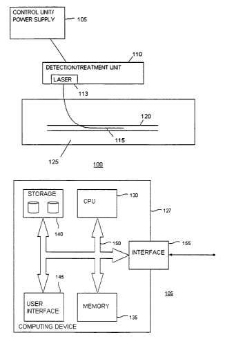
Figure 1A illustrates a detection/treatment system for detecting and/or
targeting
and/or treating vulnerable plaque in accordance with an embodiment of the
invention.
Figure 1B is a diagram illustrating a configuration of the control unit of
Figure 1A.
Figures 2A and 2,B are diagrams showing a probe/catheter in accordance with an
embodiment with the present invention. Figures 2C and 2D are diagrams showing
alternative views of Figures 2A and 2B, respectively. Figure 2E and 2F
illustrate a
probe/catheter in accordance with an embodiment of the invention.
Figures 3A, 3B and 3C are diagrams showing a probe/catheter in accordance
with an embodiment of the invention.
Figures 4A and 4B show a probe/catheter in accordance with an embodiment of
the invention.
Figures SA and SB are diagrams illustrating a light delivery element and a
light
deflection element in accordance with respective embodiments of the invention.
Figures 6A, 6B and 6C illustrate a probe/catheter in accordance with an
embodiment of the present invention.
Figure 7 shows the scheme for preparing chlorin e6 photosensitizer conjugates.
Figure 8 shows BSA- ce6 purified from unreacted ce6-NHS ester using a
Sephadex G50 column and acetone precipitation (8A: Thin Layer Chromatography;
8B:
SDS-PAGE gel visualized by fluorescence (left) and Coomassie stain (right)
before
acetone precipitation; 8C: SDS-PAGE gel visualized by fluorescence (left) and
Coomassie stain (right) after acetone precipitation)
Figure 9 shows the UV-visible absorption spectra of the purified mal-BSA-ce6
conjugates and free ce6.
Figure 10 shows the selective targeting and phototoxicity of maleylated BSA-
ce6
conjugates.
CA 02449828 2003-12-03
WO 03/003975 PCT/US02/18472
Figure 11 shows an optical multichannel analyzer used for fluorescence
localization within ex vivo aortas.
Figure 12 shows an analysis of aortic sections from rabbits injected with or
without conjugates about 24 hours after injection of the conjugate (Row 1:
confocal
fluorescence, Red=chlorin e6, Green=elastic lamina auto-fluorescence; Row 2:
fluorescence emission spectra of intimal surface of aortic segments ex vivo;
Row 3:
Hematoxylin and eosin staining of formalin fixed paraffin embedded aortic
segments;
Row 4: Verhoeff's elastic tissue stain). Column 1 shows an atherosclerotic
rabbit with
no injection of conjugate. Column 2 shows a normal non-atherosclerotic rabbit
injected
with conjugate. Column 3 shows an atherosclerotic rabbit injected with
conjugate.
Figure 13 shows a significant fluorescent signal from the intimal surface
(determined by Skin Scan) in all sections from atherosclerotic rabbits
compared to the
corresponding sections of aorta from normal rabbits injected with conjugate.
(Top:
1=thoracic aorta, 2=upper abdominal aorta below diaphragm, 3=mid abdominal
aorta,
4=lower abdominal aorta, S~elvic aorta just above bifurcation; Middle:
Measurement
of intimal surface fluorescence made by OMA-LIF system; Bottom: Data from
extraction of gross tissue samples).
Figure 14 shows the contrast between a large aortic plaque and an area of the
abdominal aorta 5 mm beneath the plaque (14A), between the balloon injured
iliac
artery and the contralateral normal artery in the same rabbit (14B), and
between the
plaque-laden aorta of an atherosclerotic rabbit and the same area of the aorta
in a normal
rabbit (14C).
Figure 15 shows a laparotomy and surgical exposure of the aorta and
surrounding tissues (15A) and a histological examination of the arteries (15B:
Top-
histopathology of PDT treated atherosclerotic aorta; Bottom- histopathology of
atherosclerotic aorta that received light but no conjugate).
DETAILED DESCRIPTION
Methods for Detecting and Treating Vulnerable Plague
CA 02449828 2003-12-03
WO 03/003975 PCT/US02/18472
11
In one aspect, the present invention relates to methods for the treatment of
vulnerable plaques by selectively targeting and destroying the inflammatory
components of vulnerable plaques. In one embodiment, a method of stabilizing a
vulnerable plaque in a subject comprises the steps of:
a) administering a therapeutically effective amount of at least one
photosensitizes composition, wherein the photosensitizes
composition is localized to a vulnerable plaque; and
b) light activating the photosensitizes composition to produce a
phototoxic species; and
c) stabilizing the vulnerable plaque against rupture.
A "vulnerable plaque" comprises an abundance of inflammatory cells, a large
lipid pool, and a thin fibrous cap. Preferably, a vulnerable plaque comprises
a fibrous
cap that is less than about 150 microns thick. More preferably, a vulnerable
plaque
comprises a fibrous cap that is less than about 100 microns thick (e.g.,
between about 60
and 100 microns thick). Preferably, a vulnerable plaque comprises a macrophage
and/or monocyte content that is greater than about 10%. More preferably, a
vulnerable
plaque comprises a macrophage and/or monocyte content that is greater than
about
25%. Preferably, a vulnerable plaque comprises a lipid content that is greater
than
about 10%. More preferably, a vulnerable plaque comprises a lipid content that
is
greater than about 25%.
"Inflammatory components" include inflammatory cells, lipids, procoagulants
(e.g., tissue factor) and enzymes or other agents that promote inhibition of
extracellular
matrix production or degradation of extracellular matrix components (e.g.,
proteases).
"Inflammatory cells" include smooth muscle cells, leukocytes, lymphocytes
(B-lymphocytes and T-lymophocytes), monocytes, macrophages, foam cells, mast
cells,
endothelial cells, platelets, erythrocytes and polymorphonuclear cells (e.g.,
granulocytes
and neutrophils). As used herein, the term, "thrombus" refers to a clot of
blood formed
within a blood vessel from a ruptured plaque and which remains attached to its
place of
origin.
As used herein, "photosensitizes" is a chemical compound, or a biological
precursor thereof, that produces a phototoxic or other biological effect on
biomolecules
CA 02449828 2003-12-03
WO 03/003975 PCT/US02/18472
12
upon photoactivation. A "phototoxic species" is an amount or variety of
reactive
species that is sufficient to product a phototoxic effect on a cell, cellular
component or
biomolecule. Preferably, the reactive species is oxygen. As used herein, a
"photosensitizer composition" comprises a photosensitizer coupled to a
macromolecular
carrier. A "macromolecular carrier" refers to a biomolecule with targeting
specificity
for one or more components comprising the vulnerable plaque.
In yet another aspect, the present invention comprises methods to detect
and/or
identify vulnerable plaques by targeting fluorescent compositions, including
photosensitizers, fluorescent dyes, and photoactive dyes, to the inflammatory
components comprising vulnerable plaques. In one embodiment, a method of
detecting
a vulnerable plaque in a subject comprises the steps of:
a) administering a fluorescent composition; and
b) localizing the composition to the vulnerable plaque; and
c) light activating the composition to illuminate the vulnerable
plaque; and
identifying the vulnerable plaque.
As used herein, a "fluorescent composition" comprises a photosensitizer,
fluorescent dye or photoactive dye coupled to a macromolecular carrier. As
used
herein, the term "fluorescent dye" refers to dyes that are fluorescent when
illuminated
with light but do not produce reactive species that are phototoxic or
otherwise capable
of reacting with biomolecules. A photosensitizer will fluoresce when
illuminated with
a certain wavelength and power of light and also produce reactive species that
is
phototoxic under the same or different wavelength and power of light. The term
"photoactive dye," as used herein, means that the illuminated photosensitizer
produces a
fluorescent species, but not necessarily a reactive species in phototoxic
amounts (i.e., a
phototoxic species). Depending on the wavelength and power of light
administered, a
photosensitizer can be activated to fluoresce and, therefore, act as a
photoactive dye,
but not produce a phototoxic species. The wavelength and power of light can be
adapted by methods known to those skilled in the art to bring about a
phototoxic effect
where desired.
CA 02449828 2003-12-03
WO 03/003975 PCT/US02/18472
13
In yet another embodiment, a method of detecting a vulnerable plaque in a
subject comprises the steps of
a) administering a detectable amount of at least one fluorescent
composition, wherein the fluorescent composition is localized to
a vulnerable plaque; and
b) light activating the vulnerable plaque to produce a fluorescent
species; and
c) identifying the vulnerable plaque.
In yet another aspect, methods of the present invention comprise a combination
of detection and treatment. In one embodiment, a method of detecting and
treating a
vulnerable plaque in a subject comprises the steps of:
a) administering a detectable amount of at least one fluorescent
composition, wherein the fluorescent composition is localized to
a vulnerable plaque; and
b) administering a therapeutically effective amount of at least one
photosensitizer composition, wherein the photosensitizer
composition is localized to a vulnerable plaque; and
c) light activating the vulnerable plaque to produce a fluorescent
species; and
d) identifying the vulnerable plaque; and
e) light activating the photosensitizer composition at the site of the
vulnerable plaque to produce a phototoxic species; and
f) stabilizing the vulnerable plaque against rupture.
In yet another embodiment, a method of detecting and treating a vulnerable
plaque in a subject comprises the steps of:
a) administering a fluorescent composition comprising a
photosensitizer coupled to a macromolecular carrier; and
b) localizing the composition to the vulnerable plaque; and
c) light activating the composition to illuminate the vulnerable
plaque; and
d) identifying the vulnerable plaque; and
CA 02449828 2003-12-03
WO 03/003975 PCT/US02/18472
14
e) light activating the photosensitizer at the site of the vulnerable
plaque to produce a phototoxic species; and
f) stabilizing the vulnerable plaque against rupture.
In yet another embodiment, a method of detecting and treating a vulnerable
plaque in a subject comprises the steps of:
a) administering a fluorescent composition comprising a
photoactive dye coupled to a macromolecular carrier; and
b) localizing the composition to the vulnerable plaque; and
c) first light activating the composition to illuminate the vulnerable
plaque; and identifying the vulnerable plaque; and
d) second light activating the photoactive dye at the site of the
vulnerable plaque to produce a phototoxic species; and
e) stabilizing the vulnerable plaque against rupture.
In yet another embodiment, a method of detecting and treating a vulnerable
plaque in a subject comprises the steps of:
a) administering a detectable amount of at least one fluorescent
composition comprising a photosensitizer coupled to a
macromolecular carrier, wherein the fluorescent composition is
localized to a vulnerable plaque; and
c) light activating the vulnerable plaque to produce a fluorescent
species; and
c) identifying the vulnerable plaque; and
d) light activating the photosensitizer at the site of the vulnerable
plaque to produce a phototoxic species; and
e) stabilizing the vulnerable plaque against rupture.
In yet another embodiment, a method of detecting and treating a vulnerable
plaque in a subject comprises the steps of
a) administering a detectable amount of at least one fluorescent
composition comprising a photoactive dye coupled to a
macromolecular carrier, wherein the fluorescent composition is
localized to a vulnerable plaque; and
CA 02449828 2003-12-03
WO 03/003975 PCT/US02/18472
b) first light activating the vulnerable plaque to produce a
fluorescent species; and
c) identifying the vulnerable plaque; and
d) second light activating the photoactive dye at the site of the
vulnerable plaque to produce a phototoxic species; and
e) stabilizing the vulnerable plaque against rupture.
In yet another embodiment, a method of detecting and treating a vulnerable
plaque in a subject comprises the steps of:
a) administering a detectable amount of at least one fluorescent
composition, wherein the fluorescent composition is localized to
a vulnerable plaque; and administering a therapeutically effective
amount of at least one photosensitizer composition, wherein the
photosensitizer composition is localized to a vulnerable plaque;
and
b) light activating the vulnerable plaque to produce a fluorescent
species; and
c) identifying the vulnerable plaque; and
d) light activating the photosensitizer composition at the site of the
vulnerable plaque to produce a phototoxic species; and stabilizing
the vulnerable plaque against rupture.
Photosensitizer Compositions
Photosensitizers of the present invention can be any known in the art,
including,
but not limited to, photofrin.RTM, synthetic diporphyrins and dichlorins,
phthalocyanines with or without metal substituents, chloroaluminum
phthalocyanine
with or without varying substituents, chloroaluminum sulfonated
phthalocyanine, O-
substituted tetraphenyl porphyrins, 3,1-meso tetrakis (o-propionamido phenyl)
porphyrin, verdins, purpurins, tin and zinc derivatives of octaethylpurpurin,
etiopurpurin, hydroporphyrins, bacteriochlorins of the tetra(hydroxyphenyl)
porphyrin
series, chlorins, chlorin e6, mono-1-aspartyl derivative of chlorin e6, di-1-
aspartyl
derivative of chlorin e6, tin(IV) chlorin e6, mete-tetrahydroxphenylchlorin,
benzoporphyrin derivatives, benzoporphyrin monoacid derivatives,
tetracyanoethylene
CA 02449828 2003-12-03
WO 03/003975 PCT/US02/18472
16
adducts of benzoporphyrin, dimethyl acetylenedicarboxylate adducts of
benzoporphyrin, Diels-Adler adducts, monoacid ring "a" derivative of
benzoporphyrin,
sulfonated aluminum PC, sulfonated AIPc, disulfonated, tetrasulfonated
derivative,
sulfonated aluminum naphthalocyanines, naphthalocyanines with or without metal
substituents and with or without varying substituents, zinc naphthalocyanine,
anthracenediones, anthrapyrazoles, aminoanthraquinone, phenoxazine dyes,
phenothiazine derivatives, chalcogenapyrylium dyes, cationic selena and
tellurapyrylium derivatives, ring-substituted cationic PC, pheophorbide
derivative,
pheophorbide alpha and ether or ester derivatives, pyropheophorbides and ether
or ester
derivatives, naturally occurring porphyrins, hematoporphyrin, hematoporphyrin
derivatives, hematoporphyrin esters or ethers, protoporphyrin, ALA-induced
protoporphyrin IX, endogenous metabolic precursors, 5-aminolevulinic acid
benzonaphthoporphyrazines, cationic imminium salts, tetracyclines, lutetium
texaphyrin, tin-etio-purpurin, porphycenes, benzophenothiazinium,
pentaphyrins,
texaphyrins and hexaphyrins, 5-amino levulinic acid, hypericin,
pseudohypericin,
hypocrellin, terthiophenes, azaporphyrins, azachlorins, rose bengal, phloxine
B,
erythrosine, iodinated or brominated derivatives of fluorescein, merocyanines,
nile blue
derivatives, pheophytin and chlorophyll derivatives, bacteriochlorin and
bacteriochlorophyll derivatives, porphocyanines, benzochlorins and
oxobenzochlorins,
sapphyrins, oxasapphyrins, cercosporins and related fungal metabolites and
combinations thereof.
Several photosensitizers known in the art are FDA approved and commercially
available. In a preferred embodiment, the photosensitizer is a benzoporphyrin
derivative ("BPD"), such as BPD-MA, also commercially known as BPD Verteporfin
or
"BPD" (available from QLT). U.S. Patent No. 4,883,790 describes BPD
compositions.
BPD is a second-generation compound, which lacks the prolonged cutaneous
phototoxicity of Photofrin" (Levy (1994) Semin Oncol 21: 4-10). BPD has been
thoroughly characterized (Richter et al., (1987) JNCI 79:1327-1331), (Aveline
et al.
(1994) Photochem Photobiol 59:328-35), and it has been found to be a highly
potent
photosensitizer for PDT. BPD tends to accumulate within atheromatous plaques.
CA 02449828 2003-12-03
WO 03/003975 PCT/US02/18472
17
Targeting BPD the inflammatory cells comprising vulnerable plaques according
to
methods of the present invention will increase the specificity of
photoactivation.
Photosensitizers known as texaphyrins also tend to accumulate within
atherosclerotic plaques. Targeting texaphyrins to the inflammatory cells
comprising
vulnerable plaques according to methods of the present invention will increase
the
specificity of photoactivation. In a preferred embodiment, the photosensitizer
is a
texaphyrin photosensitizer, such as motexafm lutetium, commercially known as
Antrin
(available from Pharmacyclics, Hayse et al., (2001) Cardiovasc. Res., 2:449-
55).
In a preferred embodiment, the photosensitizer is tin ethyl etiopurpurin,
commercially known as purlytin (available from Miravant).
Fluorescent Compositions
Fluorescent compositions of the present invention can be any known in the art,
including photosensitizers, fluorescent dyes, and photoactive dyes.
The photosensitizers used for detection of vulnerable plaques can be any knomn
in the art, as previously described. For example, hematoporphyrin derivatives
have
been used as fluorescent probes to investigate the development of human
atherosclerotic
plaques (Spokojny (1986) J. Am. Coll. Cardiol. 8:1387-1392). Hematoporphyrin
derivatives can be used for the detection of vulnerable plaques, particularly
plaques
with extensive angiogenesis (i.e., new vase vasorum are leaky, which will
prompt
accumulation of the hematoporphyrin in the plaque in addition to the selective
targeting
provided by the macromoleculax carrier).
Fluorescent dyes of the present invention can be any known in the art,
including,
but not limited to 6-carboxy-4',5'-dichloro-2', 7'-dimethoxyfluorescein
succinimidyl
ester; 5-(and-6)-carboxyeosin; 5-carboxyfluorescein; 6-carboxyfluorescein; 5-
(and-6)-
carboxyfluorescein; 5-carboxyfluorescein-bis-(5- carboxymethoxy-2-nitrobenzyl)
ether,
-alanine-carboxamide, or succinimidyl ester; 5-carboxyfluorescein succinimidyl
ester;
6-carboxyfluorescein succinimidyl ester; 5-(and-6)-carboxyfluorescein
succinimidyl
ester; 5-(4,6-dichlorotriazinyl) aminofluorescein; 2',T-difluorofluorescein;
eosin-S-
isothiocyanate; erythrosin-5-isothiocyanate; 6-(fluorescein-5-carboxamido)
hexanoic
acid or succinimidyl ester; 6-(fluorescein-5-(and-6)-carboxamido) hexanoic
acid or
succinimidyl ester; fluorescein-5-EX succinimidyl ester; fluorescein-5-
isothiocyanate;
CA 02449828 2003-12-03
WO 03/003975 PCT/US02/18472
18
fluorescein-6-isothiocyanate; Oregon Green~ 488 carboxylic acid, or
succinimidyl
ester; Oregon Green~ 488 isothiocyanate; Oregon Green~ 488-X succinimidyl
ester;
Oregon Green~ 500 carboxylic acid; Oregon Green~ 500 carboxylic acid,
succinimidyl
ester or triethylammonium salt; Oregon Crreen~ 514 carboxylic acid; Oregon
Green~
514 carboxylic acid or succinimidyl ester; Rhodamine GreenTM carboxylic acid,
succinimidyl ester or hydrochloride; Rhodamine GreenTM carboxylic acid,
trifluoroacetamide or succinimidyl ester; Rhodamine GreenTM-X succinimidyl
ester or
hydrochloride; Rhodol GreenTM carboxylic acid, N,O-bis-(trifluoroacetyl) or
succinimidyl ester; bis-(4-carboxypiperidinyl) sulfonerhodamine or
di(succinimidyl
ester); 5-(and-6)-carboxynaphthofluorescein, 5-(and-6)-
carboxynaphthofluorescein
succinimidyl ester; 5-carboxyrhodamine 6G hydrochloride; 6-carboxyrhodamine 6G
hydrochloride, 5-carboxyrhodamine 6G succinimidyl ester; 6-carboxyrhodamine 6G
succinimidyl ester; 5-(and-6)-carboxyrhodamine 6G succinimidyl ester; 5-
carboxy-
2',4',5',7'- tetrabromosulfonefluorescein succinimidyl ester or bis-
(diisopropylethylammonium) salt; 5-carboxytetramethylrhodamine; 6-
carboxytetramethylrhodamine; 5-(and-6)-carboxytetramethylrhodamine; 5-
carboxytetramethylrhodamine succinimidyl ester; 6-carboxytetramethylrhodamine
succinimidyl ester; 5-(and-6)-carboxytetramethylrhodamine succinimidyl ester;
6-
carboxy-X-rhodamine; 5-carboxy-X-rhodamine succinimidyl ester; 6-carboxy-X-
rhodamine succinimidyl ester; 5-(and-6)-caxboxy-X-rhodamine succinimidyl
ester; 5-
carboxy-X-rhodamine triethylammonium salt; LissamineTM rhodamine B sulfonyl
chloride; malachite green isothiocyanate; NANOGOLDC~ mono(sulfosuccinimidyl
ester); QSY~ 21 carboxylic acid or succinimidyl ester; QSY~ 7 carboxylic acid
or
succinimidyl ester; Rhodamine RedTM-X succinimidyl ester; 6-
(tetramethylrhodamine-
5- (and-6)-carboxamido)hexanoic acid succinimidyl ester; tetramethylrhodamine-
5-
isothiocyanate; tetramethylrhodamine-6-isothiocyanate; tetramethylrhodamine-5-
(and-
6)-isothiocyanate; Texas Red~ sulfonyl; Texas Red~ sulfonyl chloride; Texas
Red~-X
STP ester or sodium salt; Texas Red~-X succinimidyl ester; Texas Red~-X
succinimidyl ester; and X-rhodamine-5-(and-6)-isothiocyanate.
Fluorescent dyes of the present invention can be, for example, bodipy dyes
commercially available from Molecular Probes, including, but not limited to
BODIPY~
CA 02449828 2003-12-03
WO 03/003975 PCT/US02/18472
19
FL; BODIPY~ TMR STP ester; BODIPY~ TR-X STP ester; BODIPY~ 630/650-X
STP ester; BODIPY~ 650/665-X STP ester; 6-dibromo-4,4-difluoro-5, 7-dimethyl-4-
bora-3a,4a-diaza- s-indacene-3-propionic acid succinimidyl ester; 4,4-difluoro-
4-bora-
3a,4a- diaza-s-indacene-3,5-dipropionic acid; 4,4-difluoro-5,7-dimethyl- 4-
bora-3a,4a-
diaza-s-indacene- 3-pentanoic acid; 4,4-difluoro-5,7-dimethyl- 4-bora-3a,4a-
diaza-s-
indacene- 3-pentanoic acid succinimidyl ester; 4,4-difluoro-5,7-dimethyl- 4-
bora-3a,4a-
diaza-s-indacene- 3-propionic acid; 4,4-difluoro-5,7-dimethyl- 4-bora-3a,4a-
diaza-s-
indacene- 3-propionic acid succinimidyl ester; 4,4-difluoro-5,7-dimethyl- 4-
bora-3a,4a-
diaza-s-indacene- 3-propionic acid sulfosuccinimidyl ester or sodium salt; 6-
((4,4-
difluoro-5,7-dimethyl- 4-bora-3a,4a-diaza-s-indacene-3-
propionyl)amino)hexanoic
acid; 6-((4,4-difluoro-5,7-dimethyl- 4-bora-3a,4a-diaza-s-indacene-3-
propionyl)amino)hexanoic acid or succinimidyl ester; N-(4,4-difluoro-5,7-
dimethyl- 4-
bora-3a,4a-diaza-s-indacene- 3-propionyl)cysteic,acid, succinimidyl ester or
triethylammonium salt; 6-4,4-difluoro-1,3-dimethyl- 5-(4-methoxyphenyl)-4-bora-
3a,4a 4,4-difluoro-5,7-Biphenyl- 4-bora-3a,4a-diaza-s-indacene- 3-propionic
acid; 4,4-
difluoro-5,7-Biphenyl- 4-bora-3a,4a-diaza-s-indacene- 3-propionic acid
succinimidyl
ester; 4,4-difluoro-5-phenyl-4-bora- 3a,4a-diaza-s-indacene-3-propionic acid
succinimidyl ester; 6-((4,4-difluoro-5-phenyl- 4-bora-3a,4a-diaza-s-indacene-
3-
propionyl)amino)hexanoic acid or succinimidyl ester; 4,4-difluoro-5-(4-phenyl-
1, 3-
butadienyl)-4-bora-3a,4a- diaza-s-indacene-3-propionic acid succinimidyl
ester; 4,4-
difluoro-5-(2-pyrrolyl) -4-bora-3a,4a-diaza-s-indacene- 3-propionic acid
succinimidyl
ester; 6-(((4,4-difluoro-5-(2-pyrrolyl) -4-bora-3a,4a-diaza-s-indacene- 3-
yl)styryloxy)acetyl)aminohexanoic acid or succinimidyl ester; 4,4-difluoro-5-
styryl-4-
bora- 3a,4a-diaza-s-indacene-3-propionic acid; 4,4-difluoro-5-styryl-4-bora-
3a,4a-
diaza-s-indacene-3-propionic acid succinimidyl ester; 4,4-difluoro-1,3,5,7-
tetramethyl-
4-bora-3a,4a-diaza-s-indacene- 8-propionic acid; 4,4-difluoro-1,3,5,7-
tetramethyl- 4-
bora-3a,4a-diaza-s-indacene- 8-propionic acid succinimidyl ester; 4,4-difluoro-
5-(2-
thienyl) -4-bora-3a,4a-diaza-s-indacene- 3-propionic acid succinimidyl ester;
6-(((4-
(4,4-difluoro-5-(2- thienyl)-4-bora-3a,4a-diaza s-indacene-3-
yl)phenoxy)acetyl)
amino)hexanoic acid or succinimidyl ester; and 6-(((4,4-difluoro-5-(2-thienyl)
-4-bora-
3a,4a-diaza-s-indacene-3-yl)styryloxy)acetyl)aminohexanoic acid or
succinimidyl ester.
CA 02449828 2003-12-03
WO 03/003975 PCT/US02/18472
Fluorescent dyes the present invention can be, for example, alexa fluor dyes
commercially available from Molecular Probes, including but not limited to
Alexa
Fluor~ 3S0 carboxylic acid; Alexa Fluor~ 430 carboxylic acid; Alexa Fluor~ 488
carboxylic acid; Alexa Fluor~ S32 carboxylic acid; Alexa Fluor~ S46 carboxylic
acid;
Alexa Fluor~ SSS carboxylic acid; Alexa Fluor~ S68 carboxylic acid; Alexa
Fluor~
S94 carboxylic acid; Alexa Fluor~ 633 carboxylic acid; Alexa Fluor~ 647
carboxylic
acid; Alexa Fluor~ 660 carboxylic acid; and Alexa Fluor~ 680 carboxylic acid.
Fluorescent dyes the present invention can be, for example, cy dyes
commercially available from Amersham-Pharmacia Biotech, including, but not
limited
to Cy3 NHS ester; Cy S NHS ester; CyS.S NHS ester; and Cy 7 NHS ester.
Photoactive dyes of the present invention can be any photosensitizer known in
the art which will fluoresce but not necessarily produce a reactive species in
phototoxic
amounts when illuminated. Depending on the wavelength and power of light
administered, a photosensitizer can be activated to fluoresce and, therefore,
act as a
photoactive dye, but not produce a phototoxic effect unless, in some cases,
the
wavelength and power of light is suitably adapted to induce a phototoxic
effect.
Photosensitizer Composition Tar eting
Selectivity of photosensitizers for target tissues of the present invention is
achieved by using covalent conjugates, or non-covalent complexes between
photosensitizers and macromolecular carriers with targeting specificity for
one or more
components comprising the vulnerable plaque (Hasan, T. (1992) In: B. Henderson
and
T. Dougherty (eds.), Photodynamic Therapy: Basic Principles and Clinical
Applications., pp. 187-200: Marcel Dekker). Accordingly, photosensitizer
compositions
of the present invention comprise one or more photosensitizers and/or
macromolecular
carriers. Use of macromolecular carriers advantageously allows the
photosensitizer to
be selected according to optical and photophysical properties, without relying
on the
molecular structure of the photosensitizer to provide a tissue-targeting
effect.
Generally, macromolecular targeting is based on two facets of molecular
structure. Firstly features of the macromolecules such as size, charge,
hydrophobicity
and biodegradability can be manipulated to increase accumulation or retention
in the
plaque, and, secondly, the macromolecular conjugate can be designed to
recognize
CA 02449828 2003-12-03
WO 03/003975 PCT/US02/18472
21
antigens, receptors or other cell type specific structures present on
inflammatory cells.
In a preferred embodiment, the macromolecular carrier is selected from the
group
consisting of serum proteins including receptor ligands (Hamblin et al. (1994)
J.
Photochem. Photobiol. 26:147-157; Hamblin and Newman (1994) J. Photochem.
Photobiol. 26:45-56), microspheres (Bachor et al. (1991) Proc. Natl. Acad.
Sci. U.S.A.
88:1580-1584), liposomes (Polo et al. (1996) Cancer Lett. 109:57-61), polymers
(Hamblin et al. (1999) Br. J. Cancer 81:261-268), monoclonal antibodies
(Hamblin et
al. (2000) Br. J. Cancer 83:1544-1551), growth factors (Gijsens and De Witte
(1998)
Int. J. Oncol. 13:1171-1177), peptides (Krinick, (1994) J. Biomater. Sci.
Polym. Ed. 5:
303-324), hormones (Akhlynina et al. (1995) Cancer Res. 55:1014-1019) and
lipoproteins (Schmidt-Erfiuth et al. (1997) Br. J. Cancer 75:54-61).
In a preferred embodiment, photosensitizer compositions of the present
invention are coupled to macromolecular carrier comprising ligands that bind
to
"scavenger receptors." Scavenger receptors are membrane proteins expressed on
the
surface of macrophages, monocytes, endothelial cells and smooth muscle cells
that
recognize a wide range of ligands, both naturally occurring and synthetic
(Freeman et
al. (1997) Curr. Opin. Hematol. 4:41-47). Presently, there are six members of
the
scavenger receptor family belonging to three classes (e.g., class A, B or C).
After initial
binding to the scavenger receptor, the ligands are rapidly internalized and
are routed to
lysosomes for degradation by proteases and other lysosomal enzymes. The wide
and
diverse range of structures recognized by these receptors has led to them
being termed
"molecular flypaper" (I~rieger et al. (1992) Trends Biochem. Sci. 17:141-146,
1992).
The ligands are all macromolecules with a pronounced anionic charge that have
some
common conformational features (Haberland and Fogelman (1985) Proc. Natl.
Acad.
Sci. U.S.A. 82:2693-2697; Takata (1989) Biochem. Biophys. Acta. 984:273-280).
Specific targeting of compositions to J774 and other macrophage-like cells its
vitro has
been achieved with conjugates of maleylated albumin, daunorubicin and
doxorubicin
(Mukhopadhyay et al (1992) Biochem J. 284:237-241; Basu et al. (1994) FEBS
Lett.
342:249-254; Hamblin et al. (2000) Photochem Photobiol. 4:533-540).
Numerous scavenger receptor ligands known in the art (either with or without
polyethyl glycolization) can be used to target photosensitizer compositions of
the
CA 02449828 2003-12-03
WO 03/003975 PCT/US02/18472
22
present invention to vulnerable plaques, including, but not limited to
maleylated
albumin, oxidized low density lipoprotein, acetylated low density lipoprotein,
oxidized
high density lipoprotein, malondialdehyde treated proteins, lipotechoic acid,
formaldehyde treated albumin, glycated albumin, polyinosinic acid, glycated
lipoproteins, dextran sulfate, anionic phospholipids (phosphatidyl serine),
fucoidin,
carrageenan, polyvinyl sulfate, monoclonal antibodies that recognize CD1 1b or
c,
CD13, CD14, CDl6a, CD32 or CD68.
In a preferred embodiment, photosensitizer compositions of the present
invention are coupled to macromolecular carriers that target macrophages
and/or
monocytes of vulnerable plaques. These macromolecular carriers can be targeted
to, for
example, including, tenascin C,
tissue factor, tissue inhibitor of MMP 1 and 2, oxidized LDL receptor (also
known in
the art as CD36), heme oxygenase-1, human cartilage gp-39, IL-6, IL-6
receptor, IL-10,
IL-10 receptor,
lectin-like oxidized LDL-receptor ("LOX-1"), monocyte inflammatory protein-1
and
receptors thereof, and macrophage chemoattractant protein-1 receptor ("CCR-
5"). Such
macromolecular carriers can be, for example, antibodies against these
biomolecules,
ligands binding the same or analogs thereof.
In a preferred embodiment, photosensitizer compositions of the present
invention are coupled to macromolecular carriers that target T cells of
vulnerable
plaques. These macromolecular carriers can be targeted to, for example, IL-10,
IL-10
receptor, monocyte inflammatory protein-1 and receptors thereof and
transferrin. Such
macromolecular carriers can be, for example, antibodies against these
biomolecules,
ligands binding the same or analogs thereof, including, but not limited to
monoclonal
antibodies that recognize CD1, CD2, CD3, CD4, CDS, CD6, CD7, CDB, CD25, CD28,
CD44, CD71 or transferrin.
In a preferred embodiment, photosensitizer compositions of the present
invention are delivered via macromolecular carriers that target the lipid pool
of the
atheroma, including but not limited to hydrophobic photosensitizers or
photosensitizers
delivered in hydrophobic vehicles such as liposomes (with positive, neutral or
negatively charged and optionally containing cholesterol or cardiolipin)
cremaphor EL,
CA 02449828 2003-12-03
WO 03/003975 PCT/US02/18472
23
PEG/solvent mixtures, iodized castor oil, and various nanoparticles and
micellar
preparations.
In a preferred embodiment, photosensitizer compositions of the present
invention are coupled to macromolecular carriers that target proteases that
degrade
extracellular matrix (e.g., metalloproteinases), including but not limited to
monoclonal
antibodies against the protease and proteinase substrates.
In a preferred embodiment, photosensitizer compositions of the present
invention are coupled to macromolecular carriers that target the endothelial
cells of
vulnerable plaques. These macromolecular carriers can be targeted to, for
example,
endothelial adhesion molecules including, but not limited to, ICAM (also known
in the
art as CD54) and VCAM (also known in the art as CD106), angiotensin II,
angiotensin
converting enzyme (also known in the art as CD143), endothelial derived
lipase, tissue
factor, heme oxygenase-I, LOX-l, low density lipoprotein ("LDL"), high density
lipoprotein, ("HDL"), P-selectin, L-selectin and E-selectin. Such
macromolecular
carriers can be, for example, antibodies against these biomolecules, ligands
binding the
same or analogs thereof.
In a preferred embodiment, photosensitizer compositions of the present
invention are coupled to macromolecular carriers that target neutrophils of
vulnerable
plaques. These macromolecular carriers can be targeted to, for example,
myeloperoxidase. Such macromolecular carriers can be, for example, antibodies
against these biomolecules, ligands binding the same or analogs thereof.
In a preferred embodiment, photosensitizer compositions of the present
invention are coupled to macromolecular carriers that target B cells of
vulnerable
plaques. These macromolecular carriers can be targeted to, for example, IL-6,
IL-6
receptor, IL-10 and IL-10 receptor. Such macromolecular carriers can be, for
example,
antibodies against these biomolecules, ligands binding the same or analogs
thereof.
In a preferred embodiment, photosensitizer compositions of the present
invention axe coupled to macromolecular carriers that target smooth muscle
cells of
vulnerable plaques. These macromolecular carriers can be targeted to, for
example,
LOX-1. Such macromolecular carriers can be, for example, antibodies against
these
biomolecules, ligands binding the same or analogs thereof.
CA 02449828 2003-12-03
WO 03/003975 PCT/US02/18472
24
The features of a vulnerable plaque that are distinguishable from stable
atheromatous plaques advantageously distinguish vulnerable plaques from stable
atheromatous plaques according to methods of the present invention. Vulnerable
plaques comprise an abundance of inflammatory cells, a large lipid pool, and a
thin
fibrous cap. Preferably, a vulnerable plaque comprises a fibrous cap that is
less than
about 150 microns thick. More preferably, a vulnerable plaque comprises a
fibrous cap
that is less than about 100 microns thick (e.g., between about 60 and 100
microns
thick). Preferably, a vulnerable plaque comprises a macrophage and/or monocyte
content that is greater than about 10%. More preferably, a vulnerable plaque
comprises
a macrophage and/or monocyte content that is greater than about 25%.
Preferably, a
vulnerable plaque comprises a lipid content that is greater than about 10%.
More
preferably, a vulnerable plaque comprises a lipid content that is greater than
about 25%.
Thus, targeting a photosensitizer or fluorescent composition to activated
macrophages
or proteases that degrade extracellular matrix via a macromolecular carrier,
for example,
confers a selective advantage on a vulnerable plaque such that uptake of the
composition is far greater than in a non-vulnerable plaque. Thus,
photodetection or
photoactivation of the vulnerable plaque can be carried out at a wavelength
and power
of light that has an insubstantial or negligible effect on non-vulnerable
plaques. Thus,
the methods and devices of the present invention are advantageously suited for
detection and therapy of vulnerable plaques and not merely commonplace stable
atheromatous plaques.
The practice of the present invention employs, unless otherwise indicated,
conventional techniques of molecular biology (including recombinant
techniques),
microbiology, cell biology, biochemistry and immunology, which are within the
skill of
the art. Such techniques are explained fully in the literature, such as,
"Molecular
Cloning: A Laboratory Manual", second edition (Sambrook, 1989);
"Oligonucleotide
Synthesis" (Gait, 1984); "Animal Cell Culture" (Freshney, 1987); "Methods in
Enzymology" "Handbook of Experimental Immunology" (Weir, 1996); "Gene Transfer
Vectors for Mammalian Cells" (Miller and Calos, 1987); "Current Protocols in
Molecular Biology" (Ausubel, 1987); "PCR: The Polymerase Chain Reaction",
(Mullis, 1994); "Current Protocols in Immunology" (Coligan, 1991). These
techniques
CA 02449828 2003-12-03
WO 03/003975 PCT/US02/18472
are applicable to the production of the polynucleotides and polypeptides of
the
invention, and, as such, may be considered in making and practicing the
invention.
Particularly useful techniques for particular embodiments will be discussed in
the
sections that follow.
The term "coupling agent" as used herein, refers to a reagent capable of
coupling
a photosensitizer to a macromolecular carrier, or a photosensitizer or a
macromolecular
carrier to a "backbone" or "bridge" moiety. Any bond which is capable of
linking the
components such that they are stable under physiological conditions for the
time needed
for administration and treatment is suitable, but covalent linkages are
preferred. The
link between two components may be direct, e.g., where a photosensitizer is
linked
directly to a macromolecular carrier, or indirect, e.g., Where a
photosensitizer is linked
to an intermediate, e.g., linked to a backbone, and that intermediate being
linked to the
macromolecular carrier. A coupling agent should function under conditions of
temperature, pH, salt, solvent system, and other reactants that substantially
retain the
chemical stability of the photosensitizer, the backbone (if present), and the
macromolecular carrier.
A coupling agent is not always required, for example, where the fluorescent
compound is in the form of a sulfonyl chloride, isothiocyanate or succinimidyl
ester, no
coupling agent is necessary.
A coupling agent can link components without the addition to the linked
components of elements of the coupling agent. Other coupling agents result in
the
addition of elements of the coupling agent to the linked components. For
example,
coupling agents can be cross-linking agents that are homo- or hetero-
bifunctional, and
wherein one or more atomic components of the agent can be retained in the
composition. A coupling agent that is not a cross-linking agent can be removed
entirely
during the coupling reaction, so that the molecular product can be composed
entirely of
the photosensitizer,~he targeting moiety, and a backbone moiety (if present).
Many coupling agents react with an amine and a carboxylate, to form an amide,
or an alcohol and.a carboxylate to form an ester. Coupling agents are known in
the art,
see, e.g., M. Bodansky, "Principles of Peptide Synthesis", 2nd ed., referenced
herein,
and T. Greene and P. Wuts, "Protective Groups in Organic Synthesis," 2nd Ed,
1991,
CA 02449828 2003-12-03
WO 03/003975 PCT/US02/18472
26
John Wiley, NY. Coupling agents should link component moieties stably, but
such that
there is only minimal or no denaturation or deactivation of the
photosensitizer or the
macromolecular carrier.
The photosensitizer conjugates of the invention can be prepared by coupling
the
photosensitizer to macromolecular carriers using methods described in the
following
Examples, or by methods known in the art. A variety of coupling agents,
including
cross-linking agents, can be used for covalent conjugation. Examples of cross-
linking
agents include N,N'-dicyclohexylcarbodiimide (DCC), N-succinimidyl-S-acetyl-
thioacetate (SATA), N-succinimidyl-3-(2-pyridyldithio)propionate (SPDP), ortho-
phenylenedimaleimide (o-PDM), and sulfosuccinimidyl 4-(N-maleimidomethyl)
cyclohexane-1-carboxylate (sulfo-SMCC) (Karpovsky et al. (1984) J. Exp. Med.
160:1686; Liu, MA et al. (1985) Proc. Natl. Acad. Sci. USA 82:8648). Other
methods
include those described by Paulus and Behring (1985) Ins. Mitt., 78:118-132;
Brennan
et al. (1985) Science 229:81-83 and Glennie et al., (1987) J. Immuno1,139:2367-
2375.
A large number of coupling agents for peptides and proteins, along with
buffers,
solvents, and methods of use, are described in the Pierce Chemical Co.
catalog, pages
T155 -T-200, 1994 (3747 N. Meridian Rd., Rockford IL, 61105, U.S.A.; Pierce
Euxope
B.V., P.O. Box 1512, 3260 BA Oud Beijerland, The Netherlands), the contents of
which are hereby incorporated by reference.
DCC is a useful coupling agent (Pierce #20320; Rockland, IL). It promotes
coupling of the alcohol NHS to chlorin e6 in DMSO (Pierce #20684), forming an
activated ester which can be cross-linked to polylysine. DCC (N,N'-
dicyclohexylcarbodiimide) is a carboxy-reactive cross-linker commonly used as
a
coupling agent in peptide synthesis, and has a molecular weight of 206.32.
Another
useful cross-linking agent is SPDP (Pierce #21557), a heterobifunctional cross-
linker
for use with primary amines and sulfhydryl groups. SPDP has a molecular weight
of
312.4, a spacer arm length of 6.8 angstroms, is reactive to NHS-esters and
pyridyldithio
groups, and produces cleavable cross-linking such that, upon fiuther reaction,
the agent
is eliminated so the photosensitizer can be linked directly to a backbone or
macromolecular carrier. Other useful conjugating agents are SATA (Pierce
#26102) for
introduction of blocked SH groups for two-step cross-linking, which is
deblocked with
CA 02449828 2003-12-03
WO 03/003975 PCT/US02/18472
27
hydroxylamine-25-HCl (Pierce #26103), and sulfo-SMCC (Pierce #22322), reactive
towards amines and sulfhydryls. Other cross-linking and coupling agents are
also
available from Pierce Chemical Co. (Rockford, IL). Additional compounds and
processes, particularly those involving a Schiff base as an intermediate, for
conjugation
of proteins to other proteins or to other compositions, for example to
reporter groups or
to chelators for metal ion labeling of a protein, are disclosed in EPO 243,929
A2
(published Nov. 4, 1987).
Photosensitizers which contain carboxyl groups can be joined to lysine s-amino
groups in the target polypeptides either by preformed reactive esters (such as
N-hydroxy
succinimide ester) or esters conjugated in situ by a carbodiimide-mediated
reaction.
The same applies to photosensitizers that contain sulfonic acid groups, which
can be
transformed to sulfonyl chlorides, which react with amino groups.
Photosensitizers that
have carboxyl groups can be joined to amino groups on the polypeptide by an in
situ
carbodiimide method. Photosensitizers can also be attached to hydroxyl groups,
of
serine or threonine residues or to sulfhydryl groups, of serine or threonine
residues or to
sulfllydryl groups of cysteine residues.
Methods of joining components of a conjugate, e.g., coupling polyamino acid
chains bearing photosensitizers to antibacterial polypeptides, can use
heterobifunctional
cross linking reagents. These agents bind a functional group in one chain and
to a
different functional group in the second chain. These functional groups
typically are
amino, carboxyl, sulfhydryl, and aldehyde. There are many permutations of
appropriate
moieties that will react with these groups and with differently formulated
structures, to
conjugate them together (described in the Pierce Catalog and Merrifield et al.
(1994)
Ciba Found Symp. 186:5-20).
The production and purification of photosensitizers coupled to macromolecular
carriers can be practiced by methods known in the art. Yield from coupling
reactions
can be assessed by spectroscopy of product eluting from a chromatographic
fractionation in the final step of purification. The presence of uncoupled
photosensitizes and reaction products containing the photosensitizes can be
followed by
the physical property that the photosensitizes moiety absorbs light at a
characteristic
wavelength and extinction coefficient, so incorporation into products can be
monitored
CA 02449828 2003-12-03
WO 03/003975 PCT/US02/18472
28
by absorbance at that wavelength or a similar wavelength. Coupling of one or
more
photosensitizer molecules to a macromolecular carrier or to a backbone shifts
the peak
of absorbance in the elution profile in fractions eluted using sizing gel
chromatography,
e.g., with the appropriate choice of Sephadex G50, 6100, or 6200 or other such
matrices
(Pharmacia-Biotech, Piscataway NJ). Choice of appropriate sizing gel, for
example
Sephadex gel, can be determined by that gel in which the photosensitizer
elutes in a
fraction beyond the excluded volume of material too large to interact with the
bead, i.e.,
the uncoupled starting photosensitizer composition interacts to some extent
with the
fractionation bead and is concomitantly retaxded to some extent. The correct
useful gel
can be predicted be predicted from the molecular weight of the uncoupled
photosensitizer. The successful reaction products of photosensitizer
compositions
coupled to additional moieties generally have characteristic higher molecular
weights,
causing them to interact with the chromatographic bead to a lesser extent, and
thus
appear in fractions eluting eaxlier than fractions containing the uncoupled
photosensitizer substrate. Unreacted photosensitizer substrate generally
appears in
fractions characteristic of the starting material, and the yield from each
reaction can thus
be assessed both from size of the peak of larger molecular weight material,
and the
decrease in the peak of characteristic starting material. The area under the
peak of the
product fractions is converted to the size of the yield using the molar
extinction
coefficient.
The product can be analyzed using NMR, integrating areas of appropriate
product peaks, to determine relative yields with different coupling agents. A
red shift in
absorption of a photosensitizer has often been observed following coupling to
a
polyamino acid. Coupling to a larger carrier such as a protein might produce a
comparable shift, as coupling to an antibody resulted in a shift of about 3-5
nm in that
direction compared to absorption of the free photosensitizer. Relevant
absorption
maxima and extinction coefficients in O.1M NaOH/1% SDS are, for chlorin e6,
400 nm
and 150,000 M-1, cm 1, and for benzoporphyrin derivative, 430 nm and 61,000 M-
l,
cm-1.
Photosensitizers compositions of the invention include those in which a
photosensitizer is coupled directly to a macromolecular carrier, such as a
scavenger
CA 02449828 2003-12-03
WO 03/003975 PCT/US02/18472
29
receptor ligand. Other photosensitizer compositions of the invention include a
"backbone" or "bridge" moiety, such as a polyamino acid, in which the backbone
is
coupled both to a photosensitizer and to a macromolecular carrier.
Inclusion of a backbone in a composition with a photosensitizer and a
macromolecular carrier can provide a number of advantages, including the
provision of
greater stoichiometric ranges of photosensitizer and macromolecular carriers
coupled
per backbone. If the backbone possesses intrinsic affinity for a target
organism, the
affinity of the composition can be enhanced by coupling to the backbone. The
specific
range of organisms that can be targeted with one composition can be expanded
by
coupling two or more different macromolecular carriers to a single
photosensitizer-backbone composition.
Peptides useful in the methods and compounds of the invention for design and
characterization of backbone moieties include poly-amino acids which can be
homo-
and hetero-polymers of L-, D-, racemic DL- or mixed L- and D-amino acid
composition, and which can be of defined or random mixed composition and
sequence.
These peptides can be modeled after particular natural peptides, and optimized
by the
technique of phage display and selection for enhanced binding to a chosen
target, so
that the selected peptide of highest affinity is characterized and then
produced
synthetically. Further modifications of functional groups can be introduced
for
purposes, for example, of increased solubility, decreased aggregation, and
altered extent
of hydrophobicity. Examples of nonpeptide backbones include nucleic acids and
derivatives of nucleic acids such as DNA, RNA and peptide nucleic acids;
polysaccharides and derivatives such as starch, pectin, chitins, celluloses
and hemi-
methylated celluloses; lipids such as triglyceride derivatives and
cerebrosides; synthetic
polymers such as polyethylene glycols (PEGS) and PEG star polymers; dextran
derivatives, polyvinyl alcohols, N-(2-hydroxypropyl)-methacrylamide
copolymers, poly
(DL-glycolic acid-lactic acid); and compositions containing elements of any of
these
classes of compounds.
The affinity of a photosensitizer composition can be refined by modifying the
charge of a component of the composition. Conjugates such as poly-L-lysine
chlorin e6
can be made in varying sizes and charges (cationic, neutral, and anionic), for
example,
CA 02449828 2003-12-03
WO 03/003975 PCT/US02/18472
free NH2 groups of the polylysine are capped with acetyl, succinyl, or other R
groups to
alter the charge of the final composition. Net charge of a composition of the
present
invention can be determined by isoelectric focusing (IEF). This technique uses
applied
voltage to generate a pH gradient in a non-sieving acrylamide or agarose gel
by the use
of a system of ampholytes (synthetic buffering components). When charged
polypeptides are applied to the gel they will migrate either to higher pH or
to Iower pH
regions of the gel according to the position at which they become non-charged
and
hence unable to move further. This position can be determined by reference to
the
positions of a series of known IEF marker proteins.
Photosensitizer compositions of the present invention can comprise
photosensitizers coupled to antibodies, which are known in the art as
"photoimmunoconjugates." The antibody component of the photoimmunoconjugate
can
bind with specificity to an epitope present on the surface of a cell
comprising the
vulnerable plaque. As used herein, the term "binding with specificity" means
that cells
that do not express the epitope are only poorly recognized by the antibody.
The term "antibody" as used in this invention includes intact molecules as
well
as fragments thereof, such as Fab and Fab', which are capable of binding the
epitopic
determinant. Fab fragments retain an entire light chain, as well as one-half
of a heavy
chain, with both chains covalently linked by the carboxy terminal disulfide
bond. Fab
fragments are monovalent with respect to the antigen-binding site. The
antibodies of
the invention comprise whole native antibodies, bispecific antibodies;
chimeric
antibodies; Fab, Fab', single chain variable region fragments (scFv) and
fusion
polypeptides. Preferably, the antibodies of the invention are monoclonal.
The antibodies of this invention can be prepared in several ways. Methods of
producing and isolating whole native antibodies, bispecific antibodies;
chimeric
antibodies; Fab, Fab', single chain V region fragments (scFv) and fusion
polypeptides
are known in the art. See, for example, Harlow and Lane (1988) Antibodies: A
Laboratory Manual, Cold Spring Harbor Laboratory, New York (Harlow and Lane,
1988).
Antibodies are most conveniently obtained from hybridoma cells engineered to
express an antibody. Methods of making hybridomas are well known in the art.
The
CA 02449828 2003-12-03
WO 03/003975 PCT/US02/18472
31
hybridoma cells can be cultured in a suitable medium, and spent medium can be
used as
an antibody source. Polynucleotides encoding the antibody can in turn be
obtained
from the hybridoma that produces the antibody, and then the antibody may be
produced
synthetically or recombinantly from these DNA sequences. For the production of
large
amounts of antibody, it is generally more convenient to obtain an ascites
fluid. The
method of raising ascites generally comprises injecting hybridoma cells into
an
immunologically naive histocompatible or immunotolerant mammal, especially a
mouse. The mammal may be primed for ascites production by prior administration
of a
suitable composition, e.g., Pristane.
Another method of obtaining antibodies is to immunize suitable host animals
with an antigen and to follow standard procedures for polyclonal or monoclonal
production. Monoclonal antibodies (Mabs) thus produced can be "humanized" by
methods known in the art. Examples of humanized antibodies are provided, for
instance, in United States Patent Nos. 5,530,101 and 5,585,089.
"Humanized" antibodies are antibodies in which at least part of the sequence
has
been altered from its initial form to render it more like human
immunoglobulins. In one
version, the heavy chain and light chain C regions are replaced with human
sequence.
In another version, the CDR regions comprise amino acid sequences for
recognition of
antigen of interest, while the variable framework regions have also been
converted to
human sequences. See, for example, EP 0329400. In a third version, variable
regions
are humanized by designing consensus sequences of human and mouse variable
regions,
and converting residues outside the CDRs that are different between the
consensus
sequences. The invention encompasses humanized Mabs.
The invention also encompasses hybrid antibodies, in which one pair of heavy
and light chains is obtained from a first antibody, while the other pair of
heavy and light
chains is obtained from a different second antibody. Such hybrids may also be
formed
using humanized heavy and light chains.
Construction of phage display libraries for expression of antibodies,
particularly
the Fab or scFv portion of antibodies, is well known in the art (Heitner et
al. (2001) J
Immunol Methods 248:17-30). The phage display antibody libraries that express
antibodies can be prepared according to the methods described in U.S. Pat. No.
CA 02449828 2003-12-03
WO 03/003975 PCT/US02/18472
32
5,223,409 incorporated herein by reference. Procedures of the general
methodology can
be adapted using the present disclosure to produce antibodies of the present
invention.
The method for producing a human monoclonal antibody generally involves (1)
preparing separate heavy and light chain-encoding gene libraries in cloning
vectors
using human immunoglobulin genes as a source for the libraries, (2) combining
the
heavy and light chain encoding gene libraries into a single dicistronic
expression vector
capable of expressing and assembling a heterodimeric antibody molecule, (3)
expressing the assembled heterodimeric antibody molecule on the surface of a
filamentous phage particle, (4) isolating the surface-expressed phage particle
using
immunoaffinity techniques such as panning of phage particles against a
preselected
antigen, thereby isolating one or more species of phagemid containing
particular heavy
and light chain-encoding genes and antibody molecules that immunoreact with
the
preselected antigen.
Single chain variable region fragments are made by linking light and heavy
chain variable regions by using a short linking peptide. Any peptide having
sufficient
flexibility and length can be used as a linker in a scFv. Usually the linker
is selected to
have little to no immunogenicity. An example of a linking peptide is (GGGGS)3,
which
bridges approximately 3.5 nm between the carboxy terminus of one variable
region and
the amino terminus of another variable region. Other linker sequences can also
be used.
All or any portion of the heavy or light chain can be used in any combination.
Typically, the entire variable regions are included in the scFv. For instance,
the light
chain variable region can be linked to the heavy chain variable region.
Alternatively, a
portion of the light chain variable region can be linked to the heavy chain
variable
region, or a portion thereof. Also contemplated are compositions comprising a
biphasic
scFv could be constructed in which one component is a polypeptide that
recognizes an
antigen and another component is a different polypeptide that recognizes a
different
antigen, such as a T cell epitope.
ScFvs can be produced either recombinantly or synthetically. For synthetic
production of scFv, an automated synthesizer can be used. For recombinant
production
of scFv, a suitable plasmid containing a polynucleotide that encodes the scFv
can be
introduced into a suitable host cell, either eukaryotic, such as yeast, plant,
insect or
CA 02449828 2003-12-03
WO 03/003975 PCT/US02/18472
33
mammalian cells, or prokaryotic, such as Escherichia coli, and the protein
expressed by
the polynucleotide can be isolated using standard protein purification
techniques.
A particularly useful system for the production of scFvs is plasmid pET-22b(+)
(Novagen, Madison, WI) in E. coli. pET-22b(+) contains a nickel ion binding
domain
consisting of 6 sequential histidine residues, which allows the expressed
protein to be
purified on a suitable affinity resin. Another example of a suitable vector is
pcDNA3
(Invitrogen, San Diego, CA), described above.
Expression conditions should ensure that the scFv assumes functional and,
preferably, optimal tertiary structure. Depending on the plasmid used
(especially the
activity of the promoter) and the host cell, it may be necessary or useful to
modulate the
rate of production. For instance, use of a weaker promoter, or expression at
lower
temperatures, may be necessary or useful to optimize production of properly
folded
scFv in prokaryotic systems; or, it may be preferable to express scFv in
eukaryotic cells.
Antibody purification methods may include salt precipitation (for example,
with
ammonium sulfate), ion exchange chromatography (for example, on a cationic or
anionic exchange column run at neutral pH and eluted with step gradients of
increasing
ionic strength), gel filtration chromatography (including gel filtration
HPLC), and
chromatography on affinity resins such as protein A, protein G,
hydroxyapatite, and
anti-irrununoglobulin.
Photosensitizers can be linked to antibodies according to any method known in
the art. For example, the antibody can be directly linked to the
photosensitizer through
a polymer or a polypeptide linkage. Polymers of interest include, but are not
limited to
polyamines, polyethers, polyamine alcohols, derivitized to components by means
of
ketones, acids, aldehydes, isocyanates or a variety of other groups.
Polypeptide
linkages can comprise, for example poly-L-lysine linkages (Del Governatore et
a1.(2000) Br. J. Cancer 82:56-64; Hamblin et al. (2000) Br. J. Cancer 83:1544-
41;
Molpus et al. (2000) Gynecol Oncol 76:397-404). The antibody can be linked to
a
photosensitizer and at least one solubilizing agent each of which are
independently
bound to the antibody through a direct covalent linkage. The direct covalent
linkage
can be, for example, an amide linkage to a lysine residue of the antibody, as
described
CA 02449828 2003-12-03
WO 03/003975 PCT/US02/18472
34
in U.S. application serial No. 10/137,029, the contents of which are herein
incorporated
by reference. ,
Photosensitizer compositions of the present invention can comprise
photosensitizers linked to macromolecular carriers comprising the sequences of
naturally occurring proteins and peptides, from variants or fragments of these
peptides,
and from biologically or chemically synthesized peptides or peptide fragments.
Naturally occurring peptides which have affinity for one or more target cells
can
provide sequences from which additional peptides with desired properties,
e.g.,
increased affinity or specificity, can be synthesized individually or as
members of a
library of related peptides. Such peptides can be selected on the basis of
affinity for the
target cell.
The term "or (a) fragments) thereof' as employed in the present invention and
in context with polypeptides of the invention, comprises specific peptides,
amino acid
stretches of the polypeptides as disclosed herein. It is preferred that said
"fragment(s)
thereof' is/are functional fragment(s). The term "functional fragment" denotes
a part of
the above identified polypeptide of the invention which fulfills, at least in
part,
physiologically and/or structurally related activities of the polypeptide of
the invention.
The polypeptides of the present invention can be recombinant polypeptides
expressed in
eukaryotic cells, like mammalian cells.
Generally, recombinant DNA technology has enabled the expression of foreign
(heterologous) proteins in cell lines of choice. In this process, a vector
containing
genetic material directing a cell to produce a protein encoded by a portion of
a
heterologous DNA sequence is introduced into the host, and the transformed
host cells
can be fermented, cultured or otherwise subjected to conditions which
facilitate the
expression of the heterologous DNA, leading to the formation of large
quantities of the
desired protein. Plasmids are extensively used as vectors to clone DNA
molecules.
Most plasmid vectors are made by taking DNA from a variety of replicons
(plasmids,
bacteriophage chromosomes and bacterial chromosomes) and joining the DNA
together
(using restriction enzymes and DNA ligase) to form a plasmid that has an
origin of
replication, a selection marker (usually an antibiotic-resistance gene) and a
promoter for
expressing genes of interest in the required host cell. A vector can be, for
example, as
CA 02449828 2003-12-03
WO 03/003975 PCT/US02/18472
in U.S. Patent Nos. 5,990,091 and 6,004,777, and as in PCT/LTS00/04203.
Methods for
generation and use of recombinant vectors in vitro are well known in the art.
See
Sambrook, Fritsch and Maniatis, Molecular Cloning, A Laboratory Manual, 2nd
Ed.,
Cold Spring Harbor Laboratory Press, 1989 (e.g., procedures for isolating DNA,
constructing recombinant vectors, transfecting and transforming cells and
producing
heterologous peptides).
Furthermore, the recombinant vector can, in addition to the nucleic acid
sequences of the invention (e.g., those encoding the targeting peptide or
functional
fragments thereof), comprise expression control elements, allowing proper
expression
of the coding regions in suitable hosts. Such control elements are known in
the art and
can include a promoter, a splice cassette, translation initiation codon,
translation and
insertion site for introducing an insert into the vector. Preferably, the
nucleic acid
molecule is operatively linked to expression control sequences allowing
expression in
eukaryotic or prokaryotic cells.
Control elements ensuring expression in eukaryotic and prokaryotic cells are
well known to those skilled in the art. As mentioned herein above, they
usually
comprise regulatory sequences ensuring initiation of transcription and
optionally poly-A
signals ensuring termination of transcription and stabilization of the
transcript.
Additional regulatory elements can include transcriptional as well as
translational
enhancers, and/or naturally-associated or heterologous promoter regions.
Possible
regulatory elements permitting expression in for example mammalian cells
comprise the
CMV- HSV thymikine kinase promoter, SV40, RSV-promoter (Rous sarcoma virus),
human elongation factor la-promoter, aPM-I promoter (Schaffer et al. (1999)
Biochern.
Biophys. Res. Commun. 260:416-425), or inducible promoter(s), like,
metallothionein
or tetracyclin, or enhancers, like CMV enhancer or SV40-enhancer. For the
expression
in prokaryotic cells, a multitude of promoters including, for example, the tac-
lac-
promoter or the trp promoter, has been described. Besides elements that are
responsible
for the initiation of transcription, such regulatory elements can also
comprise
transcription termination signals, such as SV40-poly-A site or the tk-poly-A
site,
downstream of the polynucleotide. In this context, suitable expression vectors
are
known in the art such as Okayama-Berg cDNA expression vector pcDV 1
(Pharmacia),
CA 02449828 2003-12-03
WO 03/003975 PCT/US02/18472
36
pRc/CMV, pcDNAl, pcDNA3 (Invitrogen), pSPORT1 (GIBCO BRL), Casper, Casper-
HS43, pUAST, or prokaryotic expression vectors, such as lambda gtl 1.
Furthermore, depending on the expression system, leader sequences capable of
directing the polypeptide to a cellular compartment can be added to the coding
sequence
of the nucleic acid molecules of the invention and are well known in the art.
The leader
sequences) is assembled in appropriate phase with translation, initiation and
termination sequences, and preferably, a leader sequence capable of directing
secretion
of translated protein, or a protein thereof, into the periplasmic space or
extracellular
medium. Optionally, the heterologous sequence can encode a fusion protein
including
an C- or N-terminal identification peptide imparting desired characteristics,
e.g.,
stabilization of expressed recombinant products. Once the vector has been
incorporated
into the appropriate cell line, the cells are maintained under conditions
suitable for high
level expression of the nucleotide sequences.
A cell can be transfected or transformed with a recombinant vector encoding
the
targeting peptide of the present invention. Methods of transformation and
transfection
are well known in the art. The transformed cells can be grown in fermentors
and
cultured according to techniques known in the art to achieve optimal cell
growth. The
resulting transformed or transfected cell lines are genetically modified with
a nucleic
acid molecule according to the invention or with a vector comprising such a
nucleic
acid molecule. The term "genetically modified" means that the cell comprises
in
addition to its natural genome a nucleic acid molecule or vector according to
the
invention which was introduced into the cell or host or into one of its
predecessors/parents. The nucleic acid molecule or vector can be present in
the
genetically modified cell either as an independent molecule outside the
genome,
preferably as a molecule that is capable of replication, or it can be stably
integrated into
the genome of the cell.
The present invention can utilize any suitable prokaryotic or eukaryotic cell.
Suitable prokaryotic cells are those generally used for cloning like
Escherichia coli or
Bacillus subtilis. Eukaryotic cells comprise, for example, fungal or animal
cells, and
are generally used for conducting the specificity assay. Animal cells are
preferably
used for conducting the specificity assay. Suitable animal cells are, for
instance, insect
CA 02449828 2003-12-03
WO 03/003975 PCT/US02/18472
37
cells, vertebrate cells, preferably mammalian cells. Further suitable cell
lines known in
the art are obtainable from cell line depositories, like the American Type
Culture
Collection (ATCC) and the AIDS Research and Reference Reagent Program Catalog.
Derivation of primary cells from an animal, preferably a mammal, and even more
preferable a human, can also be undertaken for the purposes of establishing a
suitable
cell line.
Detectable compositions of the present invention can further comprise
macromolecular carriers that are radiolabeled. For example, photosensitizer
compositions of the present invention can comprise radiolabeled macromolecular
carriers coupled to photosensitizers. A number of radiolabeled macromolecular
carriers
have been tested for their ability to bind to and permit scintigraphic
detection of
atherothrombotic materials. These include labeled antibodies to oxidized LDL,
fibrinogen, autologous platelets, fibrin fragment El, plasminogen activators,
and
99mTc-conjugated antibodies against modified LDL (Tsimikas et al. (1999) J.
Nucl.
Cardiol. 6: 41-53).
Examples of appropriate radionuclides for use in radiolabeling include: 131h
lzsh
1231 99n1TC 18F 68Ga 67Ga 72AS 89zr 62Cu IllCu 203In 198Pb 198H 97R~ IIC and
> > > > > > > > > > > g> >
aoITI. Highly specific and sensitive labels are provided by radionuclides,
which can
then be detected using positron emission tomography (PET) or Single Photon
Emission
Computed Tomography (SPELT) imaging. Such labels may be incorporated into the
macromolecular carrier by covalent bonding directly to an atom of the carrier,
or the
label may be non-covalently or covalently associated with the carrier through
a
chelating structure or through an auxiliary molecule such as mannitol,
gluconate,
glucoheptonate, tartrate, and the like.
In general, labeling methodologies vary with the choice of radionuclide and
the
carrier to be labeled. Labeling methods are described for example in Peters et
al. (1986)
Lancet 2:946-949; Srivastava et al. (1984) Semin. Nucl. Med 14:68-82; Sinn et
al.
(1984) J. Nucl. Med. 13:180; McAfee et al. (1976) J. Nucl. Med. 17:480-487;
Welch et
al., (1977) J. Nucl. Med. 18:558-562; Thakuret et al. (1984) Semin. Nucl. Med.
14:107;
Danpure et al. (1981) Br. J. Radiol. 54:597-601; Danpure et al. (1982) Br. J.
Radiol.
CA 02449828 2003-12-03
WO 03/003975 PCT/US02/18472
38
55:247-249; Peters et al. (1982) J. Nucl. Med. 24:39-44; Gunter et al. (1983)
Radiology
149:563-566 and Thakur et al. (1985) J. Nucl. Med. 26:518-523.
After the labeling reaction is complete, the reaction mixture may optionally
be
purified using one or more chromatography steps such as Sep Pack or high
performance
liquid chromatography (HPLC). Any suitable HPLC system may be used if a
purification step is performed, and the yield of cardiovascular imaging agent
obtained
from the HPLC step may be optimized by varying the parameters of the HPLC
system,
as is known in the art. Any HPLC parameter may be varied to optimize the yield
of the
cardiovascular imaging agent of the invention. For example, the pH may be
varied,
e.g., raised to decrease the elution time of the peak corresponding to the
radiolabeled
carrier.
Photosensitizer Composition Administration
The photosensitizer compositions of the invention can be administered in a
pharmaceutically acceptable excipient, such as water, saline, aqueous
dextrose,
glycerol, or ethanol. The compositions can also contain other medicinal
agents,
pharmaceutical agents, carriers, and auxiliary substances such as wetting or
emulsifying
agents, and pH buffering agents.
Standard texts, such as Remington: The Science and Practice of Pharmacy, 17th
edition, Mack Publishing Company, incorporated herein by reference, can be
consulted
to prepare suitable compositions and formulations for administration, without
undue
experimentation. Suitable dosages can also be based upon the text and
documents cited
herein. A determination of the appropriate dosages is within the skill of one
in the art
given the parameters herein.
A "therapeutically effective amount" is an amount sufficient to effect a
beneficial or desired clinical result. A therapeutically effective amount can
be
administered in one or more doses. In terms of treatment, an effective amount
is an
amount that is sufficient to palliate, ameliorate, stabilize, reverse or slow
the
progression of a cardiovascular disease characterized by the presence of
vulnerable
plaques or otherwise reduce the pathological consequences of the impending
rupture. A
therapeutically effective amount can be provided in one or a series of
administrations.
CA 02449828 2003-12-03
WO 03/003975 PCT/US02/18472
39
The effective amount is generally determined by the physician on a case-by-
case basis
and is within the skill of one in the art.
As a rule, the dosage for in vivo therapeutics or diagnostics will vary.
Several
factors are typically taken into account when determining an appropriate
dosage. These
factors include age, sex and weight of the patient, the condition being
treated, the
severity of the condition and the form of the antibody being administered.
The dosage of photosensitizer compositions can range from 0.1 to 10 mg/kg.
Methods for administering photosensitizer compositions are known in the art,
and are
described, for example, in U.S. Patent Nos. 5,952,329, 5,807,881, 5,798,349,
5,776,966,
5,789,433, 5,736,563, 5,484,803 and by (Sperduto et al. (1991) Int. J. Radiat.
Oncol.
Biol. Phys. 21:441-6; Walther et al. (1997) Urology 50:199-206). Such dosages
may
vary, for example, depending on whether multiple administrations are given,
tissue type
and route of administration, the condition of the individual, the desired
objective and
other factors known to those of skill in the art. Where the photosensitizer
compositions
comprises a photoimmunoconjugate, dosages can vary from about 0.01 mg/m2 to
about
500 mg/m2, preferably 0.1 mg/ma to about 200 mg/m2, most preferably about 0.1
mg/m2
to about 10 mg/m2. Ascertaining dosage ranges is well within the skill of one
in the art.
For instance, the concentration of scFv typically need not be as high as that
of native
antibodies in order to be therapeutically effective. Administrations can be
conducted
infrequently, or on a regular weekly basis until a desired, measurable
parameter is
detected, such as diminution of disease symptoms. Administration can then be
diminished, such as to a biweekly or monthly basis, as appropriate.
Compositions of the present invention are administered by a mode appropriate
for the form of composition. Available routes of administration include
subcutaneous,
intramuscular, intraperitoneal, intradermal, oral, intranasal, intrapulmonary
(i.e., by
aerosol), intravenously, intramuscularly, subcutaneously, intracavity,
intrathecally or
transdermally, alone or in combination with other pharmaceutical agents.
Therapeutic
compositions of photosensitizers are often administered by injection or by
gradual
perfusion.
Compositions for oral, intranasal, or topical administration can be supplied
in
solid, semi-solid or liquid forms, including tablets, capsules, powders,
liquids, and
CA 02449828 2003-12-03
WO 03/003975 PCT/US02/18472
suspensions. Compositions for injection can be supplied as liquid solutions or
suspensions, as emulsions, or as solid forms suitable for dissolution or
suspension in
liquid prior to injection. For administration via the respiratory tract, a
preferred
composition is one that provides a solid, powder, or liquid aerosol when used
with an
appropriate aerosolizes device. Although not required, compositions are
preferably
supplied in unit dosage form suitable for administration of a precise amount.
Also
contemplated by this invention are slow release or sustained release forms,
whereby a
relatively consistent level of the active compound are provided over an
extended period.
Another method of administration is intravascular, for instance by direct
injection into the blood vessel, plaque or surrounding area.
Further, it may be desirable to administer the compositions locally to the
area in
need of treatment; this can be achieved, for example, by local infusion during
surgery,
by injection, by means of a catheter, or by means of an implant, said implant
being of a
porous, non-porous, or gelatinous material, including membranes, such as
silastic
membranes, or fibers. A suitable such membrane is GliadelC~ provided by
Guilford
Pharmaceuticals Inc.
Following administration of the photosensitizes composition, it is necessary
to
wait for the photosensitizes to reach an effective tissue concentration at the
site of the
plaque before photoactivation. Duration of the waiting step varies, depending
on
factors such as route of administration, tumor location, and speed of
photosensitizes
movement in the body. In addition, where photosensitizes compositions target
receptors
or receptor binding epitopes, the rate of photosensitizes uptake can vary,
depending on
the level of receptor expression on the surface of the cells. For example,
where there is
a high level of receptor expression, the rate of binding and uptake is
increased.
Determining a useful range of waiting step duration is within ordinary skill
in the art
and may be optimized by utilizing fluorescence optical imaging techniques.
Devices and Methods For Photosensitizes Composition Activation
Following the waiting step, the photosensitizes composition is activated by
photoactivating light applied to the site of the plaque. This is accomplished
by applying
light of a suitable wavelength and intensity, for an effective length of time,
at the site of
CA 02449828 2003-12-03
WO 03/003975 PCT/US02/18472
41
the plaque. As used herein, "photoactivation" means a light-induced chemical
reaction
of a photosensitizes, which produces a biological effect.
Target tissues are illuminated, preferably with red light. Given that red
and/or
near infrared light best penetrates mammalian tissues, photosensitizers with
strong
absorbances in the 600 nm to 900 nm range are optimal for PDT. The suitable
wavelength, or range of wavelengths, will depend on the particular
photosensitizer(s)
used. Wavelength specificity for photoactivation depends on the molecular
structure of
the photosensitizes. Photoactivation occurs with sub-ablative light doses.
Determination of suitable wavelength, light intensity, and duration of
illumination is
within ordinary skill in the art.
For photoactivation, the wavelength of light is matched to the electronic
absorption spectrum of the photosensitizes so that photons are absorbed by the
photosensitizes and the desired photochemistry can occur. Except where the
vessels
being treated are very superficial, the range of activating light is typically
between 600
and 900 nm. This is because endogenous molecules, in particular hemoglobin,
strongly
absorb light below 600 nm and therefore capture most of the incoming photons
(Parrish
et al., (1978) Optical properties of the skin and eyes. New York, NY: Plenum).
The net
effect would be the impairment of penetration of the activating light through
the tissue.
The reason for the 900 nm upper limit is that energetics at this wavelength
may not be
sufficient to produce 102, the activated state of oxygen which, without
wishing to
necessarily be bound by any one theory, is perhaps critical for successful
PDT. In
addition, water begins to absorb at wavelengths greater than about 900 nm.
The effective penetration depth, 8eff, of a given wavelength of light is a
function
of the optical properties of the tissue, such as absorption and scatter. The
fluence (light
dose) in a tissue is related to the depth, d, as: a d~8e~. Typically, the
effective
penetration depth is about 2 to 3 mm at 630 nm and increases to 5 to 6 nm at
longer
wavelengths (700-800 run) (Svaasand and Ellingsen, (1983) Photochem Photobiol.
38:293-299). These values can be altered by altering the biologic interactions
and
physical characteristics of the photosensitizes. In general, photosensitizers
with longer
absorbing wavelengths and higher molar absorption coefficients at these
wavelengths
are more effective photodynamic agents.
CA 02449828 2003-12-03
WO 03/003975 PCT/US02/18472
42
PDT dosage depends on various factors, including the amount of the
photosensitizer administered, the wavelength of the photoactivating light, the
intensity
of the photoactivating light; and the duration of illumination by the
photoactivating
light. Thus, the dose of PDT can be adjusted to a therapeutically effective
dose by
adjusting one or more of these factors. Such adjustments are within ordinary
skill in the
art.
The light for photoactivation can be produced and delivered to the plaque site
by
any suitable means known in the art. Photoactivating light can be delivered to
the
plaque site from a light source, such as a laser or optical fiber. Preferably,
the
photoactivating light is delivered by optical fiber devices that directly
illuminate the
plaque site. For example, the light can be delivered by optical fibers
threaded through
small gauge hypodermic needles. Light can be delivered by an appropriate
intravascular catheter, such as those described in U.S. Patent Nos. 6,246,901
and
6,096,289, which can contain an optical fiber. Optical fibers can also be
passed through
arthroscopes. In addition, light can be transmitted by percutaneous
instrumentation
using optical fibers or cannulated waveguides. For open surgical sites,
suitable light
sources include broadband conventional light sources, broad arrays of LEDs,
and
defocused laser beams.
Delivery can be by all methods known in the art, including transillumination.
Some photosensitizers can be activated by near infrared light, which
penetrates more
deeply into biological tissue than other wavelengths. Thus, near infrared
light is
advantageous for transillumination. Transillumination can be performed using a
variety
of devices. The devices can utilize laser or non-laser sources, (e.g.,
lightboxes or
convergent light beams).
Where treatment is desired, the dosage of photosensitizer composition, and
light
activating the photosensitizer composition, is administered in an amount
sufficient to
produce a phototoxic species. For example, where the photosensitizer
composition
includes chlorine6, administration to humans is in a dosage range of 0.5-10
mg/kg,
preferably 1-5 mg/kg more preferably 2-4 mg/kg and the light delivery time is
spaced in
intervals of 30 minutes to 3 days, preferably 12 hours to 48 hours, and more
preferably
24 hours. The light dose administered is in the range of 20-500 J/cm,
preferably 50-300
CA 02449828 2003-12-03
WO 03/003975 PCT/US02/18472
43
J/cm and more preferably 100-200 J/cm. The fluence rate is in the range of 20-
500
mw/cm, preferably 50-300 mw/cm and more preferably 100-200 mw/cm. There is a
reciprocal relationship between photosensitizer compositions and light dose,
thus,
determination of suitable wavelength, light intensity, and duration of
illumination is
within ordinary skill in the art.
Preferably, the phototoxic species induces apoptosis and not necrosis of the
cells
comprising the vulnerable plaque. Lowering the fluence rate will favor
apoptosis (e.g.,
less than 100 mw/cm, e.g., 10-60 mw/cm, for chlorine6). Determination of a
suitable
fluence rate for a photosensitizer composition is within ordinary skill in the
art.
Where the fluorescent composition comprises a photoactive dye, the wavelength
and power of light can be adjusted according to standard methods known in the
art to
control the production of phototoxic species. Thus, under certain conditions
(e.g., low
power, low fluence rate, shorter wavelength of light or some combination
thereof), a
fluorescent species is produced from the photoactive dye and any reactive
species
produced has a negligible effect. These conditions are easily adapted to bring
about the
production of a phototoxic species. For example, where the photoactive dye
comprises
chlorine6, the light dose administered to produce a fluorescent species and an
insubstantial reactive species is less than about 10 J/cm, preferably less
than about 5
J/cm and more preferably less than about 1 J/cm. Determination of suitable
wavelength, light intensity, and duration of illumination is within ordinary
skill in the
art.
In a preferred embodiment, photoactivation can be carried out using by a
specially designed intravascular device that delivers excitation light to the
plaque
surface inside the artery and receives emitted fluorescence or other
detectable signals
(e.g., heat or radioactivity) that are transmitted to an analysis instrument.
The same
device can optionally be used to deliver therapeutic light when a fluorescent
signal, or
other measurable signal (e.g., heat or radioactivity) is detected.
Fig. 1 A illustrates a detection/treatment system 100 for detecting and/or
targeting and/or treating vulnerable plaque in accordance with an embodiment
of the
invention. As shown in Fig. 1A, detection/treatment system 100 may include a
control
unit 105 and a detection/treatment unit 110, which may include a light
source/laser 113,
CA 02449828 2003-12-03
WO 03/003975 PCT/US02/18472
44
and a detection/treatment device 115, which may include a probe, a catheter,
and so
forth.
Control unit 105 may include a power supply, for example, control unit may be
coupled to a power source, for supplying power to detection/treatment unit
110.
Control uiut 105 may also include a computing device having control hardware
and/or
software for controlling, based on inputted parameters and/or detected
properties,
detection/treatment unit 110, light source/laser 113 and detection/treatment
device 115.
Fig. 1 B is a diagram illustrating a configuration of control unit 105 in
accordance with an embodiment of the invention. As shown in Fig. 1B, control
unit
105 may comprise a computing device 125, which may be a general purpose
computer
(such as a PC), workstation, mainframe computer system, and so forth.
Computing
device 125 may include a processor device (or central processing unit "CPU")
130, a
memory device 135, a storage device 140, a user interface 145, a system bus
150, and a
communication interface 155. CPU 130 may be any type of processing device for
carrying out instructions, processing data, and so forth. Memory device I35
may be
any type of memory device including any one or more of random access memory
("RAM"), read-only memory ("ROM"), Flash memory, Electrically Erasable
Programmable Read Only Memory ("EEPROM"), and so forth. Storage device 140
may be any data storage device for reading/writing from/to any removable
and/or
integrated optical, magnetic, and/or optical-magneto storage medium, and the
like (e.g.,
a hard disk, a compact disc-read-only memory "CD-ROM", CD-ReWritable "CD-RW",
Digital Versatile Disc-ROM "DVD-ROM", DVD-RW, and so forth). Storage device
140 may also include a controller/interface (not shown) for connecting to
system bus
150. Thus, memory device 135 and storage device 140 axe suitable for storing
data as
well as instructions for programmed processes for execution on CPU 130. User
interface 145 may include a touch screen, control panel, keyboard, keypad,
display or
any other type of interface, which may be connected to system bus 150 through
a
corresponding input/output device interface/adapter (not shown). Communication
interface 155 may be adapted to communicate with any type of external device,
including detection/treatment unit 110. Communication interface 155 may
further be
adapted to communicate with any system or network (not shown), such as one or
more
CA 02449828 2003-12-03
WO 03/003975 PCT/US02/18472
computing devices on a local area network ("LAN"), wide area network ("WAN"),
the
Internet, and so forth. Interface 155 may be connected directly to system bus
150, or
may be connected through a suitable interface (not shown). Control unit 105
may, thus,
provide for executing processes, by itself and/or in cooperation with one or
more
additional devices, that may include algorithms for controlling
detectioutreatment unit
110 in accordance with the present invention. Control unit 105 may be
programmed or
instructed to perform these processes according to airy communication
protocol, or
programming language on any platform. Thus, the processes may be embodied in
data
as well as instructions stored in memory device 135 and/or storage device 140
or
received at interface 155 and/or user interface 145 for execution on CPU 130.
Referring back to Fig. 1A, detection/treatment unit 110 may be a handheld
device, an automated apparatus, and the like. As shown in Fig. 1A,
detection/treatment
device 115 may be inserted and extended into a blood vessel 120, such as an
artery, in
tissue 125. Detection/treatment device 115 may be a handheld device, an
automated
apparatus, and the like. It is further noted that the elements of
detection/treatment
system 100 may be integrated into a single physical unit or may comprise any
number
of discrete units, such that any number of these elements or the functionality
thereof,
may be incorporated into a physical device. As will be described in further
detail
below, detection/treatment device 115 may include a number of light delivery
elements
for delivering detected light from targeted plaque, delivering therapeutic
light, and/or
delivering detection/excitation light.
Tn accordance with an embodiment of the invention, light source 113 may
include a pulse blue laser for delivering detection or excitation light via
detection/treatment device 115. Depending on the dye and/or excitation effect
on target
plaque as described above, reflected and/or emitted light from the target
plaque may
include light with a particular wavelength and/or frequency, which may then be
detected through detection/treatment device 115. A large number of fluorescent
probes
(e.g., photosensitizers, fluorescent dyes or photoactive dyes) and methods of
use thereof
(e.g., excitation and emission wavelengths), are described in the Molecular
Probes, Inc.
catalog, (Handbook of Fluorescent Probes and Research Chemicals, 6th Edition
by
Richard Haugland), the contents of which are hereby incorporated by reference.
CA 02449828 2003-12-03
WO 03/003975 PCT/US02/18472
46
In accordance with an embodiment of the invention where in the fluorescent
composition or photosensitizer composition includes chlorine6,
detection/excitation light
may include a wavelength of 337 nm (for example, nitrogen laser), therapeutic
light
may include a wavelength of 405 nm (for example, pump dye laser), and light or
fluorescence emitted from target plaque as a result of excitation by
detection/excitation
light may include a wavelength of 666-668 nm. The power of
detection/excitation light
may, for example, be adjusted in accordance with the specific excitation or
emission
wavelength of the particular fluorescent or photosensitizer composition used.
The
power of detection/excitation light may, for example, be adjusted in
accordance with a
size and/or dimension of blood vessel 120. The power of therapeutic light may,
for
example, be adjusted in accordance with a size and/or dimension of blood
vessel 120,
and/or the level of light detected from target plaque.
In accordance with an embodiment of the invention, detection/treatment system
100 may include a number of configurations and instruments. Algorithms that
are
designed for different types of procedures, configurations and/or instruments
may be
included for control unit 105.
It is noted that detection/treatment system 100 may be controlled remotely.
For
example, the link between control unit 105 and detection/treatment unit 110
may be a
remote link (wired or wireless) providing control unit 105 remote control over
light
source 113 and detection/treatment device 115.
While the above exemplary detection/treatment system 100 is illustrative of
the
basic components of a system suitable for use with the present invention, the
architecture shown should not be considered limiting since many variations of
the
haxdware configuration are possible without departing from the present
invention.
The present invention is additionally described by way of the following
illustrative, non-limiting Examples, that provide a better understanding of
the present
invention and of its many advantages.
As described before, target plaque may accumulate on the wall of blood
vessels,
e.g. arteries, and the like. Thus, detection/treatment device 115 embodying
the present
invention may include a probe/catheter and the like, as described below, which
may
include a number of elements for detecting the target plaque on the wall of
these blood
CA 02449828 2003-12-03
WO 03/003975 PCT/US02/18472
47
vessels, distinguishing the target plaque from non-target plaque and/or
treating the
target plaque without obstructing the blood flow through these vessels.
Figs. 2A, 2B, 2C, 2D, 2E and 2F are diagrams showing a probe/catheter 200 in
accordance with an embodiment with the present invention. As shown in Fig. 2A,
probe/catheter 200 may include an external unit 202 and an extendible internal
unit,
which may include a number of light delivery elements) 205 and light
deflection
elements) 210 and a tip 2I5. As an example, external unit 202 may include any
plastic
and/or metallic material (e.g., nitinol alloy) and the like. Fig. 2A
illustrates
probe/catheter 200 with its internal unit retracted within and extended from
external unit
202, and Fig. 2B illustrates probe/catheter 200 with its internal unit
extended and
deployed. In accordance with an embodiment of the invention, the internal unit
may be
extended and deployed to detect target plaque, then retracted to move
probe/catheter
200 to a different area within, say, blood vessel 120. For example,
probe/catheter 200
may be used to scan blood vessel 120 where probe/catheter 200 is moved along
blood
vessel 120 and the internal unit is extended every one to six millimeters to
make a
detection. A guidewire 223 may be used to guide probe/catheter 200 along blood
vessel
120 and/or extend/retract the internal unit (e.g., light delivery elements)
205 and light
deflection elements 210, and so forth) from/into external unit 202. As an
example,
guidewire 223 may include any plastic and/or metallic material (e.g., nitinol
alloy) and
the like. Light deflection elements) 210 may include a smooth surface for
contacting
the wall of blood vessel 120, thus allowing detection while probe/catheter 200
is being
moved. Detection may be made without contacting the wall or probe/catheter 200
may
also be stopped to make such a detection. Probe/catheter 200 may include four
light
delivery elements 205, each including a light deflection element 210. Each of
the four
light delivery elements 205 may be disposed such that the corresponding light
deflection elements 210 form a circumference separated by 90 degrees, as shown
by the
cross-sectional views in Figs. 2C and 2D. It is noted that probe/catheter 200
may
include any number of light delivery elements) 205 (and light deflection
elements)
210) separated by a corresponding angle around a circumference for covering a
divided
area of the surrounding wall of blood vessel 120. Probe/catheter 200 may also
be
rotatable to cover the circumference of blood vessel 120. In accordance with a
CA 02449828 2003-12-03
WO 03/003975 PCT/US02/18472
48
preferred embodiment of the invention, probe/catheter 200 may include three to
six
light delivery elements 205 (and light deflection elements 210). It is noted,
of course,
that light delivery elements 205 may be split from a single element connected
to
detection/treatment unit 1 I O or they may be separately connected to
detection/treatment
unit 110.
As will be described in further detail below, light deflection elements) 210
may
deflect external light received from blood vessel 120 into light delivery
elements) 205,
which may then deliver the received light to detection/treatment unit 110
and/or control
unit 105 for analysis. Light deflection elements) 210 may also deflect
detection/excitation light, which may be delivered from detection/treatment
unit 110
through light delivery elements) 205, and shine the detection/excitation light
onto a
target area in blood vessel 120. And so, reflected light and/or light emitted
from excited
taxget plaque may be received as described above. Depending on the dye and/or
excitation effect on target plaque as described before, the target plaque may
reflect
and/or emit light having a particular wavelength and/or frequency. Thus,
target plaque
may be identified and located by detecting and identifying light having such a
particular
wavelength and/or frequency from the light received from blood vessel 120.
Light delivery elements) 205 may include an optical fiber for delivering light
received at its corresponding light deflection elements) 210 to treatment unit
110
and/or control unit 105. Light delivery elements) 205 may also deliver
detection/excitation light from light source 113 to its corresponding light
deflection
elements) 210 where it is deflected and shone onto blood vessel 120. As shown
in Fig.
2A, light delivery elements) 205 may extend to and j oined at a tip 215.
As shown in Fig. 2B, light delivery elements) 205 may move outward so that
light deflection elements) 210 are moved towards the surrounding wall of blood
vessel
120, thus allowing better plaque detection. In accordance with an embodiment
of the
invention, light delivery elements) 205 may include a rigid and/or spring-like
structure,
for example, a plastic structure, such that the structure expands when
extended, as
shown in Fig. 2B, and may be compressed within external unit 202 when
retracted, as
shown in Fig. 2A. The rigid structure may include any elastic material so that
the
CA 02449828 2003-12-03
WO 03/003975 PCT/US02/18472
49
structure expands to substantially the same size and shape every time it is
extended as
shown in Fig. 2B.
In accordance with an embodiment of the invention, probe/catheter 200 may
include a vessel (or "balloon") 220 that may be expanded by filling it with a
fluid.
Thus, when extended as shown in Fig. 2B, vessel 220 may be filled with fluid
and
expanded, pushing light deflection elements) 210 towards the surrounding wall
of
blood vessel 120. The fluid may be any non-toxic fluid, such as saline and so
forth. As
an example, vessel 220 may include any elastic material, such as rubber or
latex, and
the like. Control unit 105 and/or detection/treatment unit 110 may control
fluid flow
to and from vessel 220 so that fluid is delivered thereto when probe/catheter
200 is
extended, and drained when probe/catheter 200 is retracted. Advantageously,
the
amount of fluid may be controlled so as to fit the size of the surrounding
blood vessel
120. In other words, less fluid may be delivered if blood vessel 120 is
relatively small
and more fluid may be delivered if blood vessel 120 is relatively large. Thus,
light
deflection elements) 210 may be moved towards the wall of a blood vessel 120
of any
size, while preventing light deflection elements) 210 from being pressed
against the
wall of a smaller blood vessel 120.
Figs. 2C and 2D are diagrams showing cross-sectional views of Figs. 2A and
2B, respectively. When expanding vessel 220 or otherwise moving light
deflection
elements) 210 towards the wall of blood vessel 120, it is important that blood
flow
through blood vessel 120 be unhindered. Therefore, iil accordance with an
embodiment
of the invention, vessel 220 may include a number of rigid elements) 225 so
that only a
particular portion of vessel 220 expands when filled with fluid. As an
example, rigid
elements) 225 may include a rigid material, for instance any plastic and/or
metallic
material (e.g., nitinol alloy), and the like. As shown in Figs. 2C and 2D,
vessel 220 may
include four rigid elements) 225, such as plastic ribbings, and the like. As
shown in
Fig. 2D, rigid elements) 225 may hold vessel 220 in place where only regions
of vessel
220 that are adjacent light delivery elements) 205 and light deflection
elements) 210
may expand outwaxd. Therefore, vessel 220 does not substantially block blood
vessel
120 when it is expanded. Light deflection elements) 210 may, thus, be moved
outward
to the wall of blood vessel 120 without obstructing blood flow.
CA 02449828 2003-12-03
WO 03/003975 PCT/US02/18472
Figs. 2E and 2F illustrate cross-sectional views of probe/catheter 200 in
accordance with an embodiment of the invention. As shown in Figs. 2E and 2F,
vessel
220 may include an isolated chamber corresponding to a particular light
deflection
element 210. Therefore, each of any number of particular light deflection
elements)
210 may correspond to such a chamber in vessel 220 so that elements) 210 can
be
individually moved towards and away from the wall of blood vessel 120, by
individually inflating and deflating each chamber. For example, as shown in
Fig. 2F, a
chamber 230 may be individually deflated (i.e., drained of fluid), in the
event that
therapeutic light may be directed to the corresponding region on blood vessel
120, say,
from tip 215, in the event that the corresponding region need not be detected
or
monitored for any reason, or to fit to a particular dimension of a blood
vessel.
Figs. 3A, 3B and 3C are diagrams illustrating a probe/catheter 300 in
accordance
with an embodiment of the invention. Probe/catheter 300 as shown in Figs. 3A
and 3B
is similar to probe/catheter 200 shown in Figs. 2A and 2B, respectively,
except that
probe/catheter 300 may include only one light delivery element 205 and
corresponding
light deflection element 210. Advantageously, the cross-sectional area of
probe/catheter
300, when extended and deployed, may be further reduced. For example, as shown
in
Fig. 3C, probe/catheter 300 may include only one prong compared to the four
prongs
shown in Fig. 2D for probe/catheter 200. As a result, blood flow obstruction
may be
further reduced. Probe/catheter 200 may include a platform 305 for supporting,
say,
vessel 220. As an example, platform 305 may include a rigid material, for
instance any
plastic and/or metallic material (e.g., nitinol alloy), and the like, so that
it is held in
place while vessel 220 expands and pushes light deflection element 210
outward. As
mentioned before, light delivery element 205 may include a rigid structure
that pushes
outward when extended from external unit 202. Platform 305 may support such a
structure.
Figs. 4A and 4B show a probe/catheter 400 in accordance with an embodiment
of the invention. As shown in Figs. 4A and 4B, probe/catheter 400 may include
light
delivery elements 205 disposed on a rigid structure that is compressed when
enclosed in
external unit 202, as shown in Fig. 4A, and expands when extended, as shown in
Fig.
4B. As described before, the rigid structure may include any elastic material
so that the
CA 02449828 2003-12-03
WO 03/003975 PCT/US02/18472
51
structure expands to substantially the same size and shape every time it is
extended as
shown in Fig. 4B. As an example, the rigid structure may include any plastic
and/or
metallic material (e.g., nitinol alloy) and the like.
Figs. 5A and SB are diagrams illustrating light delivery element 205 and light
deflection element 210 in accordance with respective embodiments of the
invention. As
shown in Fig. 5A, light deflection element 210 may include a reflective
surface 505
and/or a refractive element 510 for deflecting light from a target area back
to
detection/treatment unit 110 through light delivery element 205, and/or
deflecting
detection/excitation light from light source 113 to the target area. In
accordance with an
embodiment of the invention, light source 113 may include a light source for
therapeutic light having a difference wavelength and/or frequency. Thus, light
deflection element 210 may deflect only detection/excitation light, while
allowing
therapeutic light to pass through. Referring back to Figs. 2A and 2B, the
passed
through therapeutic light may be deflected out at tip 215 for effecting
treatment on the
surrounding wall of blood vessel 120. Probe/catheter 200 may further be
extended
and/or retracted partially when effecting treatment so as to ensure that
therapeutic light
from tip 215 reaches the areas covered by light deflection elements) 210.
Figs. 5B illustrates light deflection element 210 that may be used in
probe/catheter 400, as shown in Figs. 4A and 4B, in accordance an embodiment
of the
invention. As shown in Fig. 5B, a therapeutic light deflection unit 515 may be
placed
adjacent light deflection element 210. Since it is advantageous to target
therapeutic
light more broadly to cover tissue surrounding the detected plaque,
therapeutic light
deflection unit 515 may include a refractive material for spreading or
diffusing the
therapeutic light in all directions to cover the surrounding wall of blood
vessel 120. In
accordance with an embodiment of the invention, therapeutic light deflection
unit 515
may also include a reflective element 520 for targeting the therapeutic light
to a general
direction or a particular area. Thus, referring back to Figs. 4A and 4B, a
therapeutic
light deflection unit 515 may be disposed at the end, or tip, of each light
deflection
element 210.
In accordance with an embodiment of the invention, detection/excitation light
and
therapeutic light may be carried on separate light delivery elements.
CA 02449828 2003-12-03
WO 03/003975 PCT/US02/18472
52
Figs. 6A, 6B, and 6C illustrate a probe/catheter 600 in accordance with an
embodiment of the present invention. As shown in Fig. 6A, probe/catheter 600
may
include a detector 605, such as a scintillation detector, and the like, for
detecting
emitted and/or reflected light, radioactive signals (e.g., gamma rays, beta
rays, and so
forth), nuclear isotopes, radio frequency/microwave signals, magnetic fields,
electric
fields, temperature (e.g., heat), vibration, and so forth. By detecting any
one or more of
the foregoing, target plaque may be identified and/or located from surrounding
plaque/tissue. As further shown in Fig. 6A, probe/catheter 600 may also
include a
therapeutic light deflector 610, such as a diffusing fiber, and the like, for
diffusing
therapeutic light to surrounding plaque/tissue. As shown in Fig. 6B, detector
605 may
be independently retracted so that therapeutic light may be directed to the
general
direction or particular area where target plaque/tissue is detected.
Furthermore, as
shown in Fig. 6C, therapeutic light deflector 610 may include a reflective
element 615,
such as a shield, and the like, to block therapeutic light from diffusing to a
non-target
direction. For example, after detector 605 detects target plaque/tissue, it
may be
retracted and therapeutic light deflector 610 and reflective element 615 may
diffuse
therapeutic light only to the general direction and/or target area covered by
detector
605. In accordance with an embodiment of the invention, probe/catheter 600 may
be
rotatable in, say, blood vessel 120 so that detector 605 and therapeutic light
may be
directed in any direction therewithin.
The present invention is additionally described by way of the following
illustrative, non-limiting Examples, that provide a better understanding of
the present
invention and of its many advantages.
EXAMPLES
Example 1
Preparation and purification of photosensitizer compositions
A photosensitizer composition comprising chlorine6 ("ce6") coupled to
maleylated-albumin) was prepared for optimal targeting to macrophages of a
vulnerable
plaque animal model system.
CA 02449828 2003-12-03
WO 03/003975 PCT/US02/18472
53
Results
Four photosensitizer compositions were studied (i.e., two BSA- ce6 conjugates
and their maleylated counterparts). The N-hydroxy succinimide (NHS) ester of
ce6was
prepared by reacting approximately 1.5 equivalents of dicyclohexylcaxbodiimide
and
approximately 1.5 equivalents of NHS with approximately 1 equivalent of ce6
(Porphyrin Products, Logan, UT) in dry DMSO. After standing in the dark at
room
temperature for approximately 24 hours, the NHS ester was frozen in aliquots
for
further use. BSA (Sigma Chemical Co, St Louis, MO) (approximately 2 X 50 mg)
was
dissolved in NaHCO3 buffer (0.1 M, pH 9.3, approximately 3 ml), and
approximately
30 ~,l and approximately 120 ~1 of ce6-NHS ester added to respective tubes
with vortex
mixing. After standing in the dark at room temperature for approximately 6
hours, the
crude conjugate preparations were each divided into two approximately equal
parts.
One portion of each of the conjugate preparations was maleylated by adding
solid
malefic anhydride (approximately 20 mg) to the protein preparation in portions
and with
vortex mixing, and by adding saturated NaHCO3 solution as needed to keep the
pH
above approximately 7.0 (Takata et al. (1989) Biochim. Biophys. Acta 984:273).
The
reaction mixture was allowed to stand at room temp in the dark for
approximately 3
hours (Figure 7). Unmodified BSA was also maleylated to act as a control and
as a
competitor for the cellular uptake of conjugates.
Crude conjugate preparations (approximately 5 mg/ml) were added to
approximately 10X volume of acetone (ACS grade) slowly at approximately
4°C, and
were kept at approximately 4oC for approximately 6 hours, followed by
centrifugation
at about 4000 X g for approximately 15 minutes at about 4oC. The supernatant
was
removed and the pellet again suspended in approximately the same volume of
acetone
and the centrifugation repeated. After each precipitation step the preparation
was
monitored by thin layer chromatography (TLC). Approximately five precipitation
steps
were necessary to completely remove non-covalently bound chlorin species.
Finally,
the pellet was dissolved in approximately 2 ml PBS and dialyzed approximately
twice
against 20 L PBS overnight to remove traces of acetone.
CA 02449828 2003-12-03
WO 03/003975 PCT/US02/18472
54
Sephadex G50 column chromatography was carried out by applying the reaction
mixture from conjugation of approximately SO mg BSA with approximately 5 mg
ce6-
NHS ester to a 50 x I cm Sephadex column that was eluted with PBS at about
4oC.
The absorbance of the eluted fractions was monitored at 400 nm and at 280 nm.
A problem that can be encountered in the preparation of covalent conjugates of
tetrapyrrole photosensitizer (PS) with proteins is the tendency of the dye to
form tightly
bound non-covalent complexes, as well as conjugates. These mixtures can be
difficult
to separate into pure conjugate and non-bound dye. This is illustrated by the
attempted
use of a Sephadex G50 column to separate the BSA-ce6 conjugate from unreacted
ce6-
NHS ester and its subsequent reaction products. Monitoring of the eluted
fractions at
400 nm and at 280 nm showed a single peak that contained both ce6 and protein.
However, when the material obtained from combining the fractions was examined
by
TLC, as shown in Figure 8A, it was apparent that there was a considerable
amount of
unbound dye present. Lane 1 on the TLC shows the single peak isolated from the
size
exclusion column and demonstrates that there was still considerable unbound
ce6 present
as a fast running spot. When this material was used in cell-uptake
experiments, it was
difficult to distinguish receptor targeting between J774 and EMT-6 cell due to
indiscriminate uptake of unbound ce6 by both receptor-positive and receptor-
negative
cells. Likewise, lane 3 shows the crude mixture after maleylation and that
there was
unbound ce6 present.
Therefore, the conjugates were purified using an acetone precipitation that
allowed the lipophilic ce6 species to be retained in the acetone supernatant
and the
precipitated conjugates to be redissolved in a purified form. The sodium
dodecyl
sulfate polyacrylamide (SDS-PAGE) gels were viewed by fluorescence imaging to
localize the ce6 after staining with Coomassie Blue. Figure 8B shows the
corresponding
fluorescence and Coomassie images of BSA, BSA mixed with free ce6 and
conjugates
(BSA- ce6 1 and mal-BSA- ce6 1) after Sepahadex column chromatography, but
before
acetone precipitation. The mixture of BSA and ce6 (lanes 2a and 2b) showed
that no
fluorescence is retained by the protein band on the gel, thus demonstrating
that a
fluorescent band localizing with the protein is evidence of covalent
conjugation. The
CA 02449828 2003-12-03
WO 03/003975 PCT/US02/18472
lanes of the conjugates (3a and 3b, 4a and 4b) show that a fluorescent band
running at
the gel front remained after Sephadex chromatography.
The efficiency of the purification by acetone precipitation of the conjugates
was
confirmed by the gel electrophoresis images shown in Figure 8C. It can be seen
that the
fast running fluorescent band disappeared from both the BSA- ce6 and the mal-
BSA- ce6
(lanes 2c and 2d, 3c and 3d), while the TLC also showed the disappearance of
the fast
running spot (Figure 8A, lanes 2 and 4)
The concentrations of the constituents in the conjugates and, hence the
substitution ratios, were measured by absorbance spectroscopy. An aliquot of
the
conjugate was diluted in approximately 0.1 M NaOH/1% SDS and absorbance
between
240 nm and 700 nm scanned. The extinction coefficient of BSA at 280 nm is
approximately 47000 cm-1M-1 (Markwell et al. (1978) Anal Biochem 87:206) while
the extinction coefficient of ce6 at 400 nm is approximately 150000 cm-1M-1.
Thin
layer chromatography was performed on silica gel plates (Polygram SIL
G/LTV254,
Macherey Nagel, Duren, Germany). The chromatograms were developed with an
approximately 1:1 mixture of approximately 10% aqueous ammonium chloride and
methanol, and spots were observed with fluorescence and absorbance imaging.
SDS-
PAGE was carried out essentially according to the methods known in the art
(Laemmli
(1970) Nature 227:680). Gradients of 4-10% acrylamide were used in a non-
reducing
gel and ce6 was localized on the gel by a fluorometer (excitation at 400-440
nm
bandpass filter, emission scanned from 580-720 nm longpass filter (ChemiImager
4000,
Alpha Innotech Corp, San Leandro, CA). Proteins were localized by Coomassie
blue
staining.
The UV-visible absorption spectra of the purified mal-BSA- ce6 conjugates with
the two substitution ratios measured at approximately equal protein
concentrations are
shown in Figure 9, together with free ce6 at approximately the same
concentration as
was present in mal-BSA-ce6 2. Similar spectra were obtained for BSA- ce6 1 and
2.
Using the values for molar extinction coefficients of BSA at 280 nm of
approximately
47000 cm 1M-1 (Markwell et al (1978) Anal Biochem 87:206) and ce6 at 400 nm of
approximately 150000 cm 1M'1, and correcting for the small absorbance of ce6
at 280
CA 02449828 2003-12-03
WO 03/003975 PCT/US02/18472
56
nm, then the substitution ratios can be calculated to be mal-BSA- ce6 1 ratio
equals
approximately 1 protein to approximately 1 dye, and mal-BSA- ce6 2, ratio
equals
approximately 1 protein to approximately 3 dye.
Example 2
Macrophage-Tar: eg tiny of Photosensitizers
The photosensitizer composition comprising chlorine6 coupled to maleylated-
albumin described in Example 1 was shown to accumulate in the macrophage-rich
plaques of an animal model system that are analogous to vulnerable plaques in
humans.
Thus, methods of the present invention provide highly specific intravascular
detection
and therapy of vulnerable plaques.
Cell Culture
J774.A1 (J774) and RAW 264.7 mouse macrophage-like cell lines, together
with EMT-6 mouse mammary fibrosarcoma cells, were obtained from ATCC
(Rockville, MD). Cells were grown in RPMI 1640 media containing HEPES,
glutamine, 10% fetal calf serum (FCS), 100 U/ml penicillin and 100 ~,g/ml
streptomycin. They were passaged by washing with phosphate buffered saline
(PBS)
without Ca2+and Mg2+ and by adding trypsin-EDTA to the plate for 10 minutes at
37°C.
Rabbits
Male New Zealand white rabbits weight 2.5-3.0 kg (Charles River Breeding
Lab) were maintained on a 2% cholesterol-6% peanut oil diet (ICN) for 6 weeks.
Results
For cellular uptake studies, cells were grown to approximately 90% confluency
in twenty-four well plates and the conjugate or photosensitizer was added in
about 1 ml
medium containing approximately 10% serum to each well. The concentration
range
for the conjugates and free cep was between approximately 0.5 and 4 ~M ce6
equivalent
and the incubation time was approximately 3 hours. After incubation at 37oC,
the
medium was removed and cells were washed about three times with approximately
1 ml
sterile PBS and incubated with approximately 1 ml trypsin-EDTA for about 20
minutes
(OVCAR-5) or 60 minutes (J774). The cell suspension was then removed and
CA 02449828 2003-12-03
WO 03/003975 PCT/US02/18472
57
centrifuged (about 5 minutes at approximately 250 X g). The trypsin
supernatant was
aspirated and retained and the pellets (frequently visibly fluorescent under
long wave
UV) were dissolved in about 1.5 ml of approximately O.1M NaOH / 1% SDS for at
least
about 24 hours to give a homogenous solution. The trypsin supernatant was
checked
for the presence of fluorescence to quantify any surface binding which might
easily be
removed by trypsin. The fluorescence was measured using an excitation
wavelength of
400 nm and the emission scanned from 580 to 700 nm in order to calculate the
peak
area (7~max = 664 nm). A series of dilutions in approximately 1.5 ml O.1M NaOH
/ 1%
SDS of known concentrations of each separate conjugate and photosensitizer was
scanned for fluorescence as above in order to prepare calibration curves to
allow for
quantitation of the ce6 by conversion of the measured peak areas into mol ce6
equivalent. The protein content of the entire cell extract was then determined
by a
modified Lowry method (Marwell et al (1978) Anal Biochem 87:296) using BSA
dissolved in approximately O.1M NaOH/1% SDS to construct calibration curves.
Results were expressed as mol of ce6 per mg cell protein. For measuring the
cellular
uptake at 4oC, pre-cooled growth media was used and the plates with cells were
cooled
to about 4°C in an ice-bath for approximately 20 minutes before the
addition of
photosensitizer solutions as well as after the addition. The incubation was
carried out in
the normal atmosphere in the dark (e.g., plates wrapped in aluminum foil).
Cells were seeded in 24 well plates, at densities of approximately 100,000
cells
in about 1 ml medium. After about 24 hours, the cells were given about 1 ml
fresh
medium containing 10% serum and a specific conjugate or free ce6 (ces
equivalent
concentration of approximately 4 nmoles per well) and incubated for about 3
hours at
37°C. Immediately prior to illumination, the cells were washed about 3
times with PBS
with Mga+/Ca2+ and the wells were replenished with approximately 1 ml medium
containing HEPES and about 10% FCS. Light (660 nm) was delivered from beneath
the wells from a diode laser at a fluence rate of about 50 mW/cm2 via a fiber
optic
coupled microscope objective. Wells were illuminated in blocks of four defined
by a
black mask placed beneath the 24 well plate. Fluences were about 2, 5, and 10
J/cm2.
After completion of illumination, the dishes were returned to the incubator
for a further
CA 02449828 2003-12-03
WO 03/003975 PCT/US02/18472
58
approximately 24 hour incubation. Cell survival was determined by the 3-(4,5-
dimethylthiazol-2-yl)-2,5-diphenyltetrazolium bromide (MTT) assay, which
measures
mitochondrial dehydrogenase activity. It has been extensively used for
measuring
viability of cell cultures after PDT and has been shown to have close
correlation with
colony forming assays (McHale et al (1988) Cancer Letters 41:315).
Approximately
twenty-four hours post illumination, the cells were given fresh media and
about 100 ~,1
MTT (5 mg/ml) solution was added to each well and cells were incubated at
37°C.
After approximately 1 hour incubation, the supernatant medium was gently
aspirated
and about 1 ml of DMSO was added to lyse the cells and dissolve the deep blue
formazan. Plates were gently shaken on an orbital shaker in the dark for
approximately
15 min to complete the dissolution of any formazan crystals and the blue DMSO
solution was transferred to 96 well plates (about 200 ~.1 per well, 5 wells
per well of 24-
well plate). Absorbance was read on an automated plate reader (Model 2550 EIA,
Bio-
Rad Laboratories, Hercules, CA) at 570 nm. Data points were the average of 3
wells of
the 24 well plate (15 wells of 96 well plate).
The role of scavenger receptors in the uptake of these conjugates was tested
by
measuring the reduction in the cellular content of photosensitizer produced by
competing the uptake with a ligand known to be recognized by the scavenger
receptor.
The reduction in cellular uptake was then related to protection of the cells
from
phototoxicity. Increasing amounts of unlabeled mal-BSA were added
simultaneously
with the conjugates to J774 and OVCAR-5 cells and incubated for about 3 hours.
Approximately 0, 50, 100, and 200 ~,g/ml mal-BSA were used, representing a
range of
about 0.25 to 3 fold molar excess of the BSA contained in approximately 4 ~,M
BSA-
ce6 or mal-BSA- ce6. The cellular uptakes and phototoxicities were measured as
described above.
Mouse-macrophage cells (J774 or RAW264.7) took up more than ten times as
much dye as non-target EMT-6 cells and, upon illumination with modest levels
of red
light, were killed approximately 1000 times as much. The maleylated conjugates
had
greater macrophage selectivity and, therefore, higher phototoxicity than their
non-
maleylated counterparts (Figure 10).
CA 02449828 2003-12-03
WO 03/003975 PCT/US02/18472
59
After 1 week on the peanut oil diet, the abdominal aorta was denuded of
endothelium by a modified Baumgartener technique. Briefly, each animal was
anesthetized with a mixture of ketamine and xylazine and the right femoral
artery was
isolated. Subsequently, a 4F Fogarty embolectomy catheter was introduced via
arteriotomy and advanced under fluoroscopic guidance to the level of the
diaphragm.
The balloon was then inflated to 3 psi above balloon inflation pressure and
three passes
were made down the abdominal aorta with the inflated catheter. The femoral
artery was
subsequently ligated and the wound closed.
For fluorescence localization within ex vivo aortas, aortic segments were cut
open and flattened and the luminal side examined by spectrofluorometry using
either a
fiber-bundle based double monochromator spectrofluorimeter (Skin Scan, Spex
Figure),
where emission spectra (excitation 400 nm, emission 580-720 nm) was collected
about
every 3 mm across the entire area of the exposed intimal surface, or an
optical
multichannel analyzer (Figure 11).
For confocal fluorescence microscopy, selected parts of the aortas were snap
frozen in liquid nitrogen and approximately 10 - 20 pm frozen sections were
prepared.
These sections underwent laser scanning confocal fluorescence microscopy to
detect the
tissue distribution of the ce6. The red intracellular fluorescence from ce6
together with
green tissue auto-fluorescence was imaged in the cells in 10 p,m frozen
sections.
Sections were examined with a laser scanning confocal fluorescence microscope.
A
Leica DMR confocal laser fluorescence microscope (Leica Mikroskopie and
Systeme
GmbH, Wetzler, Germany) (excitation 488 nm argon laser) and 4X-40X air
immersion
lens or a 100X oil immersion objective was used to image at a resolution of
1024 x
1024 pixels. Two channels collected fluorescence signals in either the green
range (580
nm dichroic mirror plus 530 nm (+/- 10 nm) bandpass filter) or the red range
(580 nm
dichroic mirror plus 590 nm longpass filter) and were displayed as false color
images.
These channels were overlaid using TCS NT software (Version 1.6.551, Leica
Lasertecluuk, Heidelberg, Germany) to allow visualization of overlap of red
and green
fluorescence. These sections were also stained by immunohistochemistry using
macrophage specific monoclonal antibodies and conventional H&E staining. Other
parts of normal and atherosclerotic aorta were cut into small pieces, weighed
and
CA 02449828 2003-12-03
WO 03/003975 PCT/US02/18472
dissolved in sodium hydroxide/SDS and the tissue content of ce6 was determined
by
spectrofluorimetry as previously described (Hamblin et al (2000) Br. J. Cancer
83:1544).
Figure 12 shows an analysis of aortic sections from rabbits injected with or
without conjugate (approximately 2 mg/kg in PBS) about 24 hours after
injection of the
conjugate. Row 1 shows confocal fluorescence micrographs of frozen aortic
sections
(Red = chlorin e6, Green = elastic lamina auto-fluorescence). Row 2 shows
fluorescence emission spectra (excitation = 400 nm) of initmal surface of
aortic
segments ex vivo. Row 3 shows Hematoxylin and eosin staining of formalin fixed
paraffin embedded aortic segments. Row 4 shows Verhoeff's elastic tissue
stain. The
confocal micrographs showed red fluorescence from the PS (ce6) and green auto-
fluorescence principally from the elastic lamina of the arteries. Column 1
shows an
atherosclerotic rabbit with no injection of conjugate. There was no red ce6
fluorescence
in the tissue section, nor any fluorescence signal from the intimal surface.
Column 2
shows a normal non-atherosclerotic rabbit injected with conjugate. There is a
small
amount of red fluorescence visible in the adventitia rather than the intima in
the
fluorescence micrographs, and a small fluorescence emission signal from the
intimal
surface. Column 3 shows an atherosclerotic rabbit injected with conjugate.
There was
a large amount of red fluorescence visible in the plaque and this gave a
corresponding
large fluorescence emission signal from the intimal surface.
The intimal fluorescence signal was measured from different sections of aortas
from atherosclerotic and normal rabbits. The areas of the abdominal aorta that
received
balloon injury developed greater amounts of plaque than the neighboring
thoracic and
lower abdominal aortas. The results from the intimal fluorescence measurements
were
confirmed by extracting sections of the aortas and measuring fluorescence with
a
spectrofluorimeter that gives a measure of the number of ce6 molecules in the
tissue
sections.
Figure 13 shows a significant fluorescent signal from the intimal surface
(determined by Skin Scan) in all sections from atherosclerotic rabbits
compared to the
corresponding sections of aorta from normal rabbits injected with conjugate,
but
particularly higher in the sections from the balloon-injured areas. The
section 1 depicts
CA 02449828 2003-12-03
WO 03/003975 PCT/US02/18472
61
thoracic aorta, section 2 depicts upper abdominal aorta below the diaphragm,
section 3
depicts mid-abdominal aorta, section 4 depicts lower abdominal aorta and
section 5
depicts pelvic aorta just above bifurcation. At least 6 separate measurements
were
taken from each artery segment. By the nature of the balloon injury, sections
3 and 4
generally sustained a more severe endothelial injury than other sections and
hence
developed more severe atherosclerosis. These plaques are extremely rich in
marcophages and therefore, are most analogous to vulnerable plaques in humans.
Such
lesions represent the animal model system used by those of skill in the art to
study the
features of vulnerable plaques. The signal from atherosclerotic rabbit section
3 was
greater than normal control section 3 (p < 0.0005) and the signal from
atherosclerotic
section 4 was greater than normal control section 4 (p<0.005).
The second measurement of intimal surface fluorescence was made by the
OMA-LIF system described above. At least 15 separate fluorescence measurements
were taken from each artery segment. In addition, the iliac artery through
which the
balloon was passed also sustained an injury due to its relatively small
diameter
compared to aortic section 5 and, therefore, developed atherosclerosis
compared to the
uninjured iliac artery. Figure 13 shows a similar pattern to the Skin Scan
measurements
that can be seen with highly significant increases in fluorescence in the
arteries with
inflamed plaque (i.e., balloon injured aorta and iliac). Sections 3, 4 and
injured iliac of
atherosclerotic compared to normal control had p values < 0.0001, while
section 5 and
uninjured iliacs had p values < 0.0005. Accordingly, the less severe plaques
of section
are distinguishable from the macrophage-rich plaques of sections 3 and 4.
Sections 1
and 2 were not significantly different in atherosclerotic and normal rabbits.
To corroborate the selectivity of the macrophage targeted conjugate for
inflamed
plaque, the dye molecules were extracted out of the pre-weighed tissue
sections by
dissolving the tissue in a solvent (1M NaOH/0.2% SDS) designed to preserve ce6
fluorescence. These dissolved tissue sections were then measured on the
spectrofluorimeter and the fluorescent signal was divided by the tissue weight
to give a
value per gram tissue. At least four pieces of tissue were dissolved for each
data point.
The differences between atherosclerotic and normal rabbits were significant
(p<0.05)
for sections l, 2, and 4. The lower level of significance in this assay was
probably due
CA 02449828 2003-12-03
WO 03/003975 PCT/US02/18472
62
to the inability to sample as many points as was possible with the surface
fluorescence
measurement. In addition, it is possible that surface measurement of
fluorescence was
more sensitive than bulk extraction for detecting macrophage population
because
macrophages are more likely to be concentrated in the inflamed surface of the
plaque.
In Figure 14a, a marked contrast was seen between a large aortic plaque and an
area of the abdominal aorta 5 mm beneath the plaque. In Figure 14b, another
marked
contrast was seen between the balloon injured iliac artery and the
contralateral normal
artery in the same rabbit. Similarly, Figure 14c shows a contrast between the
plaque-
laden aorta of an atherosclerotic rabbit and the same area of the aorta in a
normal rabbit.
These spectra were obtained in a rabbit that had received an overdose of
anesthesia.
The rabbit received a laparotomy that exposed the abdominal aorta and iliac
arteries.
The rabbit also had an arterotomy in the right leg to expose the femoral
artery. The
fiber-optic catheter of the OMA-LIF apparatus was advanced through the femoral
and
iliac arteries, to the abdominal aorta, up to the thoracic aorta. Spectra were
obtained
and the fiber optic catheter pulled back about 5 mm each time successive
spectra were
obtained. By palpation of the outside of the artery, the position of the
catheter in
relation to plaques was determined
Thus, a novel method has been developed for targeting a photosensitizer
composition to the activated macrophages of a vulnerable plaque with high
specificity.
Example 3
In vivo Photodynamic TheraRy
An intravascular fluorescence catheter that eff ciently localized a
fluorescence
signal from a vulnerable plaque in the rabbit coronary (although not limited
to rabbit)
through flowing blood was developed. In addition, a therapeutic intravascular
light
delivery system was developed that illuminated the vulnerable plaques through
flowing
blood with the appropriate wavelength, fluence and fluence rate of light,
achieving the
desired therapeutic effect.
Results
PDT in rabbit aorta was demonstrated to be possible in vivo in living rabbits
through flowing blood without undue harm to the rabbits and with no short-term
toxicity. The same parameters were used as above (photosensitizer composition,
dose
CA 02449828 2003-12-03
WO 03/003975 PCT/US02/18472
63
and time interval) in order to be able to correlate treatment effects with
previously
determined dye localization in plaque lesions. Animals (one atherosclerotic
and one
normal rabbit, each injected with Mal-BSA-ce6 24 hours previously; and one
atherosclerotic rabbit that received no injection) were anesthetized as before
and a
cylindrical diffusing tipped fiber optic (length of tip = 2 cm, diameter =1
mm) was
advanced to a position midway along the balloon-injured abdominal aorta. The
fiber
had a SMA connector at the proximal end that can be connected to a diode laser
emitting light at approximately 665 nm for Mal-BSA-ce6. Light was delivered at
a
fluence rate of approximately 100 mW/cm of diffusing tip and a total fluence
of
approximately 100 J/cm was delivered. At the conclusion of the illumination,
the fiber
was withdrawn and the arteriotomy and overlying wound were closed. Animals
were
sacrificed 48 hours later. They received a laparotomy and surgical exposure of
the aorta
and surrounding tissues (Figure I SA). The top panel of Figure 15A shows Iight
delivery into the abdominal aorta via a diffusing tip catheter inserted into
the femoral
artery, demonstrating the feasibility of intra-arterial illumination. The
middle panel of
Figure 15A shows atherosclerotic aorta that is thick such that light did not
penetrate to
extra-aortic tissue. The bottom panel of Figure 1 SA shows normal aorta that
is thin
such that light penetrates to give a slight but definite damage to psoas
muscle.
Complete aortas and iliac arteries were removed from the PDT treated normal
and
atherosclerotic rabbits and control (no Mal-BSA- ce6 injection)
atherosclerotic rabbit
and were examined by histology using H&E, Masson Trichrome and Verhoeffs
stain.
The two rabbits that received both the photosensitizer composition and light
showed no ill effects of the treatment during the two days they lived before
sacrifice.
At necropsy, the atherosclerotic rabbit had no gross damage visible in the
illuminated
aortic section or surrounding tissue. By contrast, the normal rabbit had some
minor
damage visible in the pare-aortic muscle, consisting of hemorrhage and
purpura.
Without being bound by theory, it is hypothesized that this damage was caused
because
the thickness of the normal artery was much less than the atherosclerotic
aorta, and
consequently, much of the light penetrated the artery and illuminated the
surrounding
tissue. The atherosclerotic rabbit that received light, but no conjugate was
associated
with any change to artery or surrounding tissue.
CA 02449828 2003-12-03
WO 03/003975 PCT/US02/18472
64
Histological examination of the arteries (Figure 15B. Top panel:
histopathology
of PDT treated atherosclerotic aorta; Bottom panel: histopathology of
atherosclerotic
aorta that received light but no conjugate) showed changes in the illuminated
section of
the atherosclerotic rabbit that received both conjugate and light, consistent
with PDT
effects in the targeted tissue. There was evidence of apoptosis (pyknotic
nuclei) and an
inflammatory infiltrate in the plaque (Figure 15B, left panel), together with
some
coagulative necrosis (Figure 15B, middle panel), and extravasated erythrocytes
that may
have come from the vasa vasorum and visible damage in the plaque (Figure 15B,
right
panel). Together, these histological data indicate that the treatment produced
favorable
modifications of plaque histology and reduced vulnerability. Histological
changes were
not observed in the normal rabbit that received photosensitizer composition
and light,
nor were any changes observed in the atherosclerotic rabbit that received
light but no
conj ugate.
This technology satisfies the clear need for a new therapy that allows
localized
stabilization of vulnerable plaques in coronary arteries with the consequent
reduced risk
of rupture.