Note: Descriptions are shown in the official language in which they were submitted.
CA 02450100 2006-11-06
HIGH VISIBILITY TRAVERSABLE BOOM SYSTEM
Field of the Invention
The present invention relates generally to a traversing boom system.
More particularly, the present invention relates to a traversing boom system
for
a forklift providing a high degree of operator visibility.
Background of the Invention
Forklifts have long been known in the construction industry and typically
comprised a frame having a front and rear set of opposing wheels, an engine
and
drivetrain, an operator cockpit, and a load handling attachment at the end of
a
boom. Forklifts having a high level of maneuverability were usually preferred
for the transport and placement of loads in and around construction sites. The
typical construction site also required, for safe and efficient operation,
that a
forklift provide its operator with a high level of visibility of the terrain
surrounding the forklift. Operator visibility of the terrain surrounding a
forklift
was crucial to avoid injury to personnel working thereabout and to avoid
damaging nearby structures, waterlines or electrical lines. When provided
with a high degree of visibility of the surrounding terrain, an operator
TDO-RED #8342291 v. I
CA 02450100 2003-12-09
WO 02/102703 PCT/US02/18193
could quickly and efficiently operate the forklift with confidence it was
being done
safely.
Prior to transporting a load, a forklift operator would usually engage the
load
with the load handling attachment at the end of the boom, lift the load from
the surface
upon which it rested by elevating the boom, and adjust the boom and load to a
transport configuration. The transport configuration positioned the load at a
sufficient
distance from the ground to ensure that neither the load nor the load handling
attachment of the boom would inadvertently encounter the ground during
transportation. The load elevation varied according to the terrain and would
necessarily be greater when the terrain was rough than when the terrain was
relatively
even. Stability dictated, however, that the load not be positioned too far
above the
forklift center of gravity. Other aspects of the environment in which the
forklift was
used also limited the elevation of the load in the transport configuration.
For example,
a forklift employed to move a load from a construction site into a building
might have
been required to pass through a doorway. At that time, the vertical elevation
of the
boom, load handling attachment or load could be no higher than the vertical
opening of
the doorway.
Forklifts having a variable reach or extensible boom were also well known in
the construction industry. An extensible boom was usually pivotally connected
to the
forklift's frame, at, for example, a rearward portion thereof, and extended
forward over
the frame. The operator cockpit was typically mounted at the side of the frame
between the front and rear wheels. The engine was often placed at the side of
the
frame opposing the operator cockpit or at the rear of the frame adjacent to
the pivotal
connection between the boom and the frame. As known to those of ordinary skill
in
the art, the extensible boom was employed to facilitate the handling of a load
at a
-2-
CA 02450100 2003-12-09
WO 02/102703 PCT/US02/18193
location to which the forklift could not travel. For example, placement or
retrieval of a
load on a second or higher floor of a building could require the forklift
operator to
elevate and extend the boom to place or retrieve the load.
Alternatively, some forklifts have mounted the boom pivot to a traversing
boom carriage capable of travelling along portions of the forklift length
rather than
being pivotally mounted directly to the forklift's frame in a fixed manner.
Traversing
boom carriages typically employed a hydraulically controlled boom carriage
mounted
to a pair of parallel rails that enabled the boom carriage, and thus the boom
attached
thereto, to traverse the rails longitudinally towards the front or rear of the
forklift
frame.
As is known to one of ordinary skill in the art, traversing boom carriages
were
employed to increase the load handling ability of a forklift. For example,
delivery of a
load to the second or higher floor of a building with a fixed boom-pivot
required
raising the boom to the necessary angle, extending the boom to the approximate
desired length to positioning the load handling device adjacent to the
delivery area and
then performing an iterative process involving adjusting the length and height
of the
boom to transport the load laterally to the desired position while maintaining
the load
of a constant elevation. A traversing boom carriage eliminated this iterative
process
by allowing the forklift operator to position the load adjacent to the
delivery area and
simply causing the boom carriage to traverse forward to locate the load in the
delivery
area. The traversing carriage provided a simple manner of obtaining lateral
movement
of the load while maintaining it at a relatively constant elevation.
The traversing carriage of the traversing boom type forklift added a new
factor
to the transport configuration of forklifts. As known to those skilled in the
art, the
boom carriage was typically positioned at or near its rearward most position
at the rear
-3-
CA 02450100 2003-12-09
WO 02/102703 PCT/US02/18193
of the forklift frame for stability. However, the guide rails along which the
carriage
traveled, as well as the carriage itself, obstructed the forklift operator's
view of the
terrain on the side of the forklift opposite the operator's cockpit when the
forklift was
in the transport configuration. The outermost guide rails and the carriage
became the
limiting factors of operator visibility of that terrain.
-4-
CA 02450100 2003-12-09
WO 02/102703 PCT/US02/18193
Summary of the Invention
It is one of the principal objectives of the present invention to provide a
rough
terrain forklift that provides optimum terrain visibility to an operator.
It is another objective of the present invention to provide a forklift having
a
boom pivotally mounted on a traversable carriage and an engine mounted between
frame rails.
It is still another objective of the present invention to provide a forklift
having
a low overall profile and optimum terrain visibility to an operator.
It is yet another objective of the present invention to provide a forklift
having a
traversing boom carriage.
It is another objective of the present invention to provide a forklift having
a
traversing boom carriage mounted on guide rails that facilitate optimum
operator
visibility of the terrain surrounding the forklift.
It is an additional objective of the present invention to provide a forklift
having
a traversing boom carriage mounted on a pair of guide rails, one or both of
which are
located low on the forklift to facilitate optimum operator visibility of the
terrain
surrounding the forklift.
It is a further objective of the present invention to provide a forklift
having a
pair of boom carriage guide rails, the outer one of the guide rails being
lower than the
inner guide rail.
It is yet another objective of the present invention to provide a traversing
boom
carriage for a forklift having the outer one of a pair of legs longer than the
inner one of
the pair of legs to accommodate a vertical offset of a pair of corresponding
guide rails
on the forklift.
-5-
CA 02450100 2003-12-09
WO 02/102703 PCT/US02/18193
It is still another objective of the present invention to provide a traversing
boom forklift in which the carriage is guided by a single set of guide tracks.
These and other objectives of the present invention will become apparent upon
review of the attached written description including the figures and claims.
-6-
CA 02450100 2003-12-09
WO 02/102703 PCT/US02/18193
Brief Description of Drawings
FIG. 1 is a perspective view of one embodiment of the forklift of the present
invention with a traversing boom carriage in a rearward position and showing,
in
phantom, the boom carriage in a forward position.
FIG. 2 is a perspective view of one embodiment of the traversing boom
carriage of the present invention.
FIG. 3 is a left side elevational view of the traversing boom carriage
depicted
in FIG. 2.
FIG. 4 is a front side cross-sectional view of one embodiment of the guide
rails
of the present invention and an elevational view of the carriage of the
present
invention mounted therein.
FIG. 5A is a front side elevational view of one embodiment of the forklift of
the present invention with the frame and guiderails in cross-section to
illustrate the
operator's line of sight over the frame to the terrain adjacent to the
carriage guide rails
as well as the operator's line of sight if the outer guide rails were of equal
elevation to
the inner guide rail as with prior art traversing boom guide rails.
FIG. 5B is a broader view of the illustration of FIG. 5A indicating the
increased view of the terrain provided by the embodiment of the present
invention
depicted in FIG. 5A.
FIG. 6 is a right side elevational view of one embodiment of the forklift of
the
present invention with the boom carriage in a rearward position.
-7-
CA 02450100 2003-12-09
WO 02/102703 PCT/US02/18193
Detailed Description
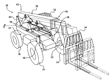
Figure 1 illustrates a perspective view of a forklift 10 representing one
embodiment of the present invention. As shown in Figure 1, the forklift 10
comprises
a mainframe 12 with a front set of wheels 14 and a rear set of wheels 18
coupled to a
front axle 22 and a rear axle (not shown) respectively. An engine 26 (see Fig.
5) and
drivetrain (not shown) are located between a left frame rai128 and a right
frame rail 30
of the mainframe 12 to deliver power to the front 22 and/or rear (not shown)
axles. An
engine casing (not depicted) may enclose the engine 26 to protect the engine
26 from
foreign objects and to protect the operator from injury. A cockpit 32 is
mounted to the
left frame rai128 of the mainframe 12 for housing an operator 88 (See Fig. 5).
Additionally, the cockpit 32 houses controls (not shown) known to one of
ordinary
skill in the art for operating the various mechanical features described
herein.
A load handling device 34 is pivotally mounted to a first end 36 of a boom 38.
Other handling devices, such as a loading fork, bucket, crane hook, or other
load
handling device known in the art, may be employed with the present invention.
The
boom 38 shown in Figure 1 is a telescoping extensible boom. The boom 38 may
alternatively be a fixed length boom, or other boom known in the art. The load
handling device 34 is selectively tiltable using a hydraulic load handling
cylinder (not
shown) as is known to those skilled in the art.
A second end 42 of the boom 38 is pivotally mounted to a boom carriage 44.
Two hydraulic boom cylinders 46 are connected between the boom 38 and the boom
carriage 44 along either side of the boom carriage 44. The hydraulic boom
cylinders
46 operate to raise and lower the boom first end 36. As the hydraulic boom
cylinders
46 extend to raise the boom first end 36 the load handling cylinder may
contract to
maintain the load handling device 34 level to the ground. Similarly, as the
hydraulic
-8-
CA 02450100 2003-12-09
WO 02/102703 PCT/US02/18193
boom cylinders 46 contract to lower the boom 38, the load handling cylinder
may
extend to maintain the load handling device 34 level to the ground. The load
handling
cylinder may be extended or contracted independent of the hydraulic boom
cylinders
46.
The embodiment depicted in Figure 1 is a rough terrain forklift 10 allowing a
tight turning radius, having a low profile, a centrally mounted engine 26 and
drivetrain
and the mainframe 12 as described in Application Serial No. 09/286,152.
Additionally,
the pivotal mount of the boom 38 is elevated from the mainframe 12 to provide
the
operator 88 of the forklift 10 with optimum visibility of the terrain
surrounding the
forklift 10 as described in Application Serial No. 09/286,152. The boom
carriage 44
and rail configuration of the present invention can be employed with any type
of
boom, hydraulic system, or frame configuration.
Figures 2 and 3 illustrate one embodiment of the boom carriage 44 of the
present invention. The boom carriage 44 has a left side plate 48 and a right
side plate
50. The side plates 48, 50 are each affixed one to the other by a top brace 52
and a
diagonal brace 54 which extend therebetween. The carriage depicted in Figure 1
shows top and diagonal braces 52, 54 of different configurations than those
depicted in
Figure 2. Other configurations will become evident to one of ordinary skill in
the art.
The braces 52, 54 can be affixed to the side plates 48, 50 by any other manner
known
in the art. The side plates 48, 50 each provide a boom pivot 56, 58
respectively, for
rotatably mounting the boom 38 thereto as well as hydraulic support portions
60, 62
respectively, for attaching the hydraulic boom cylinders 46 thereto. Mounting
of the
boom 38 and hydraulic boom cylinders 46 to the boom carriage 44 may be
accomplished in any manner known to those of ordinary skill in the art.
-9-
CA 02450100 2003-12-09
WO 02/102703 PCT/US02/18193
Each side plate 48, 50 comprises a guide track engaging portion, which in
Figure 2 comprises rollers 63, 64, 65, 66 rotatably mounted thereto. The
carriage right
side plate 50 is provided with a front roller 63 and a rear roller 64. The
carriage left
side plate 48 is provided with a front roller 65 and a rear roller 66. The
rollers 63, 64
attached to the carriage right side plate 50 may be referred to herein
collectively as the
outer rollers 63, 64 (indicating the outermost relationship of the rollers 63,
64 with
respect to the operator) and the rollers 65, 66 attached to the carriage left
side plate 48
may be referred to herein collectively as the inner rollers 65, 66 (indicating
the
innermost relationship of the rollers 65, 66 with respect to the operator 88).
Other
guide track engaging portions consistent with the principles set forth herein
are
contemplated.
As shown in Figure 3, the carriage right side plate 50 is longer than the
carriage
left side plate 48 so that it extends farther below the top brace 52 so as to
vertically
offset the outer rollers 63, 64 below the inner rollers 65, 66. In one
embodiment, the
outer rollers 63, 64 are vertically offset approximately 4.5 inches below the
inner
rollers 65, 66, as measured from their respective axes of rotation. That is,
the outer
rollers 63, 64 are located approximately 4.5 inches farther below the top
brace 52 than
are the inner rollers 65, 66. As described more fully below, the outer rollers
63, 64
engage an outer guide track 83 and the inner rollers engage an inner guide
track 81 to
guide the carriage 44 as it traverses the forklift 10.
In one embodiment, the overall length of the boom carriage 44 has a relatively
shorter length than previous carriages, enabling the boom carriage 44 to be
further
removed from an operator's view when in a rearward position such as when
configured
for travel as depicted in Fig. 6. In one embodiment, the boom carriage 44 is
approximately 83 inches long, as measured from the centerline of the front
left roller
-10-
CA 02450100 2003-12-09
WO 02/102703 PCT/US02/18193
65 to the centerline of the rear left roller 66. According to well known
principals of
physics, shortening the length of the boom carriage 44 increases the loads
experienced
by the rollers 63, 64, 65, 66 due to the moment created by the weight of the
load and
the boom 38. The shorter carriage length reduces the moment arm of the boom
carriage 44, which increases the amount of force exerted on the rollers 63,
64, 65, 66
and, therefore, the guide tracks 81, 83. In one embodiment, the increased
loads are
partially sustained by using larger diameter rollers 63, 64, 65, 66 than
previous
designs. For example, the rollers 63, 64, 65, 66 are approximately 5'/8 inches
in
diameter in one embodiment. The rollers 63, 64, 65, 66 may utilize roller
bearings, as
opposed to the bronze bushings used in past designs, to help compensate for
the
increased loading caused by the shortened boom carriage 44 of this embodiment.
Other carriage lengths and roller diameters, consistent with the principals
set forth
herein, are contemplated.
As shown in Figure 4, the left frame rail 28 comprises an inner guide rail 68
and the right frame rail 30 comprises an outer guide rai170. The terms inner
and outer
are again used with reference to the cockpit 32 and the operator 88 therein.
The outer
guide rail 70 is vertically offset from the inner guide rail 68 to accommodate
the offset
between the outer rollers 63, 64 and the inner rollers 65 and 66. The inner
and outer
guide rails 68, 70 respectively each have a lower rail portion 72, 74, an
upper rail
portion 76, 78, and a side rail portion 80, 82, respectively, defining an
inner guide
track 81 and an outer guide track 83 to accommodate the guide track engaging
portions
depicted as inner rollers 65, 66 and outer rollers 63, 64 respectively. Lower
rail
portions 72, 74, may, optionally, be readily replaceable to absorb the wear
and tear to
which the lower rail portions 72, 74 are subjected. In this embodiment, the
lower rail
portions 72, 74 are replaceably secured to the respective upper rail portions
76, 78 by
-11-
CA 02450100 2003-12-09
WO 02/102703 PCT/US02/18193
bolts, as shown, or by any other manner known to those of ordinary skill in
the art.
The rollers 63, 64, 65, and 66 operate within the respective guide tracks 81,
83
allowing the boom carriage 44 to traverse the guide rails 68, 70 in the
conventional
manner of traversing boom forklifts as will be understood by one of ordinary
skill in
the art. The figures depict the right front roller 63 and the right rear
roller 64 both
being accommodated in the outer guide track 83 as well as the left front
roller 65 and
the left rear roller 66 both being accommodated in the inner guide track 81.
This
configuration differs to prior traversing boom configurations that employed a
pair of
opposing upper guide tracks for the rear rollers and a distinct pair of
opposing lower
guide tracks for the front rollers to vertically offset the front rollers from
the rear
rollers. Eliminating this vertical offset in the present invention allows the
guide tracks
to be lowered the maximum amount to provide the maximum visibility of the
terrain
possible. Manufacture of the present guide tracks 81, 83, is also simpler than
prior
guide tracks. It will become evident to one of ordinary skill in the art,
however, that
the offset of the present invention between the inner and outer rails could be
accomplished, with concomitant benefits, on a forklift employing separate
pairs of
guide tracks for the front and rear rollers.
The rollers 63, 64, 65, 66 are accommodated in the guide rails 68, 70 such
that
each roller 63, 64, 65, 66 contacts either the lower rail portion 72, 74 or
the upper rail
portion 76, 78 depending on the loading of the boom carriage 44. For example,
generally, when the load handling device 34 is loaded, a downward force is
transferred
through the boom carriage 44 in front of the center of gravity of the boom
carriage 44,
the moment created by the load will cause the front rollers 63, 65 to ride
along the
lower rail portions 72, 74 and the rear rollers 64, 66 to ride along the upper
rail
portions 76, 78. The side rail portions 80, 82 provide lateral support to the
rollers 63,
-12-
CA 02450100 2003-12-09
WO 02/102703 PCT/US02/18193
64, 65, 66 and are configured to prevent the boom carriage 44 from escaping
the guide
tracks 81, 83 defined by the guide rails 68, 70.
In one embodiment, the height of the guide rails 68, 70, measured from the
lowest surface of the lower rail portion 72, 74 to the uppermost surface of
the upper
rail portion 76, 78, is approximately 8.66 inches. The height of the guide
tracks 81,
83, measured from the lowest surface of the upper rail portion 76, 78 to the
uppermost
surface of the lower rail portion 72, 74, is approximately 5.91 inches. The
width of the
guide rails 68, 70, measured from the innermost surface to the outermost
surface of the
guide rails 68, 70, is approximately 2.8 inches. The thickness of the side
rail portions
80, 82 is approximately 0.75 inches. The thickness of the lower rail portion
72, 74 is
approximately 0.75 inches. The thickness of the upper rail portion 76, 78 is
approximately 2.0 inches. Additionally, in this embodiment, the guide rails
68, 70
may be constructed of welded steel plates. Alternatively, the guide rails 68,
70 may be
constructed from formed steel channels formed, by way of example only, by
extrusion.
In the embodiment depicted in Figures 1 and 4, guide rails 68, 70 are attached
to the
frame rails 28, 30, respectively, by welding. Alternate methods of attaching
the guide
rails 68, 70 to the frame rails 28, 30, such as bolting, will be evident to
one of ordinary
skill in the art. The guide tracks 81, 83 of the present invention may
alternatively be
formed into the frame rails 28, 30 themselves, such as by forging or machined
therein.
Other methods for providing the guide tracks 81, 83 of the present invention
will
become apparent to one of ordinary skill in the art.
As described above with respect to Figures 2 and 3, the outer rollers 63, 64
are
located approximately 4.5 inches below the inner rollers 65, 66 in one
embodiment.
This offset is illustrated in Fig. 4 as distance a. Other magnitudes of offset
a are
contemplated. In the same embodiment, the center of the outer guide track 81
is
-13-
CA 02450100 2003-12-09
WO 02/102703 PCT/US02/18193
located approximately 4.5 inches, or other dimension a, lower than the center
of the
inner guide track 83 to accommodate the offset of the rollers 63, 64, 65, 66.
Offsetting
the guide tracks 81, 83 lowers the uppermost surface of the outer guide rai170
thereby
increasing the operator's visibility of the terrain thereadjacent by a
distance b as
depicted in Fig. 5B. The inner guide rail 68 may also be lowered with respect
to prior
inner guide rails. Indeed, in one embodiment of the present invention, which
is not
depicted, the inner guide rail 68 is lowered to an elevation equal to the
outer guide rail
70 and the carriage left and right side plates 48, 50 are, accordingly, of
equal length.
In either configuration, the carriage left and right side plates 48, 50 must
be of
sufficient height to elevate the carriage top brace 52 over the engine 26 or
other
equipment which resides between the frame rails 28, 30. However, when physical
limitations prevent the lowering of the inner guide rail 68 to the same
lowered
elevation as desired for the outer guide rail 70, the vertical offset a of the
present
invention as depicted in Figs. 4, 5, 5A and 5B provide increase terrain
visibility
without requiring a lowered inner guide rai168. Such physical limitations may
include, by way of example only, mountings (not depicted) for the cockpit 32
or access
holes in the inner frame rail 28 to provide access to the engine, transmission
or
drivetrain.
The lower limit of the outer guide rail 70 will be dictated by the desired
ground
clearance and the desired maximum loading capability of the forklift 10. In
one
embodiment, it has been found that the inner and outer frame rails 28 and 30
need be
approximately 16 inches high and 21.5 inches high, respectively, when
comprised of
approximately 1.5 inch thick welded plate steel for a forklift 10 having a
recommended lifting capacity of 8,000 lbs. Other configurations are
contemplated and
will be recognized by one of ordinary skill in the art.
-14-
CA 02450100 2003-12-09
WO 02/102703 PCT/US02/18193
One or more of the rollers 63, 64, 65, 66 may comprise a thrust slide or an
adjustable roller with a cam-like mechanism for adjusting its thrust, or
position of the
roller 63, 64, 65, 66 from side to side. For example, the inner rollers 65, 66
may be
adjustable rollers and the outer rollers 63, 64 may be fixed rollers to
promote acquiring
a perfect fit between the boom carriage 44 and the offset guide rails 68, 70
during the
assembly of the forklift 10.
The traversing motion of the boom carriage 44 along the guide rails 68, 70 may
be facilitated by one or a pair of carriage hydraulic cylinders 84, one
located along
each of the guide rails 68, 70. As shown in Figure 1, the offset rails 68, 70
may
traverse the length of the mainframe 12 allowing the boom carriage 44 to
traverse the
length of the mainframe 12. Figs. 1 and 6 depict the boom carriage 44 in a
fully
rearward, or nearly fully rearward, position which may constitute a transport
configuration. The transport configuration is designed to promote a higher
degree of
visibility when the forklift 10 is in motion as well as to allow transport of
the forklift
10 without the load encountering the earth. In the transport configuration,
the boom
carriage 44 is entirely out of the line of sight of the operator 88 housed in
the cockpit
32 when looking towards the terrain adjacent to the outside rail 70.
Therefore, as
depicted in Fig. 6, the short length of the boom carriage 44 of the present
invention
assures that the increased operator visibility provided by the lowered outer
guide rail
70 of the present invention is appreciable by the operator. Moreover, locating
the
engine 26 immediately below the carriage 44 in its depicted location in Fig. 6
assures
that the engine 26 remains out of the sight of the operator regardless of the
position of
the carriage 44. Fig. 6 also depicts a front carriage stop 92 proximate the
foremost
portion of the guide rails 68, 70. A rear carriage stop (not depicted) may
also be
-15-
CA 02450100 2003-12-09
WO 02/102703 PCT/US02/18193
located proximate to the rearmost portion of the guide rails 68,70. Figure 1
also
illustrates, in phantom, the boom carriage 44 in a forward position.
Fig. 5A illustrates the increased visibility provided by the offset guide
rails 68,
70. As described above, the cockpit 32 is located along the left frame rail
28. When
the operator 88 housed in the cockpit 32 looks towards the terrain adjacent to
the right
frame rail 30, and the boom carriage 44 is in a rearward position to remove it
from the
operator's line of sight, the operator's view is limited by the height of the
outer guide
rail 70. In Figure 5, the operator's line of sight over the offset guide rails
68, 70 of the
present invention is demonstrated by line A. Line B illustrates what the
operator's line
of sight would have been had the outside guide rai170 been located at an
elevation
equal to the inner guide rail 68 in the traditionally configuration. Fig. 5B
demonstrates
the additional terrain which the operator is able to view as a result of the
present
invention. By lowering the outside guide rail 70 of the present invention the
operator's
view of the surrounding terrain is increased by the distance b shown in Fig.
5B.
Although the engine 26 and drivetrain may be mounted to the mainframe 12 in
a number of configurations, using the offset rails 68, 70, in conjunction with
a
centrally mounted engine 26 and drivetrain affords a further increase of
visibility.
For all of the above reasons, the forklift 10 of the present invention
increases
an operator's visibility of the surrounding terrain.
It should be noted that various changes and modifications to the presently
preferred embodiments described herein will be apparent to those skilled in
the art.
Such changes and modifications may be made without departing from the spirit
and
scope of the present invention and without diminishing its attendant
advantages. It is,
therefore, intended that such changes and modifications be covered by the
appended
claims.
-16-