Note: Descriptions are shown in the official language in which they were submitted.
CA 02450114 2003-12-04
WO 02/100278 PCT/US02/18278
Sampling Devices and Methods Utilizing a Horizontal Capillary Test Strip
Reference to Related Applications/Patents
This application is related to and claims priority from provisional US Patent
Applications, Serial Nos. 60/296,949 filed on June 8, 2001 (1106P) and
60/315,873 filed on August 29, 2001 (1107P). The disclosures in the foregoing
applications and patents are hereby incorporated by reference.
Background of the Invention
Field of the Invention
The present invention relates to the sampling of a bodily fluid obtained
from an incision in the skin, and more particularly to acquiring the fluid
with a test
strip placed adjacent to the skin. The invention also may include the
combination
of such sampling devices and methods with incising, expressing, and/or testing
systems.
Description of the Prior Art
The acquisition and testing of bodily fluids is useful for many purposes,
and continues to grow in importance for use in medical diagnosis and
treatment,
and in other diverse applications. In the medical field, it is desirable for
lay
operators to perform tests routinely, quickly and reproducibly outside of a
laboratory setting, with rapid results and a readout of the resulting test
information.
Testing can be performed on various bodily fluids, and for certain
applications is
particularly related to the testing of blood and/or interstitial fluid. Such
fluids can
be tested for a variety of characteristics of the fluid, or analytes contained
in the
fluid, in order to identify a medical condition, determine therapeutic
responses,
assess the progress of treatment, and the like.
The testing of bodily fluids basically involves the steps of obtaining the
fluid sample, transfernng the sample to a test device, conducting a test on
the fluid
sample, and displaying the results. These steps are generally performed by a
plurality of separate instruments or devices.
One method of acquiring the fluid sample involves inserting a hollow
needle or syringe into a vein or artery in order to withdraw a blood sample.
However, such direct vascular blood sampling can have several limitations,
CA 02450114 2003-12-04
WO 02/100278 PCT/US02/18278
2
including pain, infection, and hematoma and other bleeding complications. In
addition, direct vascular blood sampling is not suitable for repeating on a
routine
basis, can be extremely difficult and is not advised for patients to perform
on
themselves.
The other common technique for collecting a bodily fluid sample is to form
an incision in the skin to bring the fluid to the skin surface. A lancet,
knife or other
cutting instrument is used to form the incision in the skin. The resulting
blood or
interstitial fluid specimen is then collected in a small tube or other
container, or is
placed directly in contact with a test strip. The fingertip is frequently used
as the
fluid source because it is highly vascularized and therefore produces a good
quantity of blood. However, the fingertip also has a large concentration of
nerve
endings, and lancing the fingertip can therefore be painful. Alternate
sampling
sites, such as the palm of the hand, forearm, earlobe and the like, may be
useful for
sampling, and are less painful. However, they also produce lesser amounts of
blood. These alternate sites therefore are generally appropriate for use only
for test
systems requiring relatively small amounts of fluid, or if steps are taken to
facilitate the expression of the bodily fluid from the incision site.
Various methods and systems for incising the skin are known in the art.
Exemplary lancing devices are shown, for example, in United States Patent Nos.
Re 35,803, issued to Lange, et al. on May 19, 1998.; 4,924,879, issued to
O'Brien
on May 15, 1990; 5,879,311, issued to Duchon et al. on February 16, 1999;
5,857,983, issued to Douglas on January 12, 1999; 6,183,489, issued to Douglas
et
al. on February 6, 2001; 6,332,871, issued to Douglas et al. on December 25,
2001;
and 5,964,718, issued to Duchon et al. on October 12, 1999. A representative
commercial lancing device is the Accu-Chek Softclix lancet.
Patients are frequently advised to urge fluid to the incision site, such as by
applying pressure to the area surrounding the incision to milk or pump the
fluid
from the incision. Mechanical devices are also known to facilitate the
expression
of bodily fluid from an incision. Such devices are shown, for example, in
United
States Patent Nos. 5,879,311, issued to Duchon et al. on February 16, 1999;
5,857,983, issued to Douglas on January 12, 1999; 6,183,489, issued to Douglas
et
CA 02450114 2003-12-04
WO 02/100278 PCT/US02/18278
al. on February 6, 2001; 5,951,492, issued to Douglas et al. on September 14,
1999; 5,951,493, issued to Douglas et al. on September 14, 1999; 5,964,718,
issued
to Duchon et al. on October 12, 1999; and 6,086,545, issued to Roe et al. on
July
11, 2000. A representative commercial product that promotes the expression of
bodily fluid from an incision is the Amira AtLast blood glucose system.
The acquisition of the produced bodily fluid, hereafter referred to as the
"sampling" of the fluid, can take various forms. Once the fluid specimen comes
to
the skin surface at the incision, a sampling device is placed into contact
with the
fluid. Such devices may include, for example, systems in which a tube or test
strip
is either located adjacent the incision site prior to forming the incision, or
is moved
to the incision site shortly after the incision has been formed. A sampling
tube
may acquire the fluid by suction or by capillary action. Such sampling systems
may include, for example, the systems shown in US Patent Nos. 6,048,352,
issued
to Douglas et al. on April 11, 2000; 6,099,484, issued to Douglas et al. on
August
8, 2000; and 6,332,871, issued to Douglas et al. on December 25, 2001.
Examples
of commercial sampling devices include the Roche Compact, Amira AtLast,
Glucometer Elite and Therasense Freestyle test strips.
The bodily fluid sample may be analyzed for a variety of properties or
components, as is well known in the art. For example, such analysis may be
directed to hematocrit, blood glucose, coagulation, lead, iron, etc. Testing
systems
include such means as optical (e.g., reflectance, absorption, fluorescence,
Raman,
etc.), electrochemical, and magnetic means for analyzing the sampled fluid.
Examples of such test systems include those in US Patent Nos. 5,824,491,
issued to
Priest et al. on October 20, 1998; 5,962,215, issued to Douglas et al. on
October 5,
1999; and 5,776,719, issued to Douglas et al. on July 7, 1998.
Typically, a test system takes advantage of a reaction between the bodily
fluid to be tested and a reagent present in the test system. For example, an
optical
test strip will generally rely upon a color change, i.e., a change in the
wavelength
absorbed or reflected by dye formed by the reagent system used. See, e.g., US
Patent Nos. 3,802,842; 4,061,468; and 4,490,465.
CA 02450114 2003-12-04
WO 02/100278 PCT/US02/18278
4
A common medical test is the measurement of blood glucose level. The
glucose level can be determined directly by analysis of the blood, or
indirectly by
analysis of other fluids such as interstitial fluid. Diabetics are generally
instructed
to measure their blood glucose level several times a day, depending on the
nature
and severity of their diabetes. Based upon the observed pattern in the
measured
glucose levels, the patient and physician determine the appropriate level of
insulin
to be administered, also taking into account such issues as diet, exercise and
other
factors.
In testing for the presence of an analyte such as glucose in a bodily fluid,
test systems are commonly used which take advantage of an oxidation/reduction
reaction which occurs using an oxidase/peroxidase detection chemistry. The
test
reagent is exposed to a sample of the bodily fluid for a suitable period of
time, and
there is a color change if the analyte (glucose) is present. Typically, the
intensity
of this change is proportional to the concentration of analyte in the sample.
The
color of the reagent is then compared to a known standard which enables one to
determine the amount of analyte present in the sample. This determination can
be
made, for example, by a visual check or by an instrument, such as a
reflectance
spectrophotometer at a selected wavelength, or a blood glucose meter.
Electrochemical and other systems are also well known for testing bodily
fluids for
properties or constituents.
It has been known in the art to use test strips which are positioned adjacent
to the skin in order to acquire a bodily fluid present at an incision site.
Such uses
are shown, for example, in US Patent Nos. 5,951,492, issued to Douglas et al.
on
September 14, 1999; 6,099,484, issued to Douglas et al. on August 8, 2000; and
6,332,871, issued to Douglas et al. on December 25, 2001. The test strips are
typically positioned against the skin or are held slightly above the skin, at
a
location which positions the fluid inlet of the test strip adjacent to the
incision site.
In these applications, however, it has been possible for the bodily fluid to
move
into the area between the underside of the test strip and the skin. The
presence of a
hydrophilic bottom surface of the test strip will tend to promote this
movement of
the fluid. Additionally, a narrow space between the test strip and the skin
can
CA 02450114 2003-12-04
WO 02/100278 PCT/US02/18278
function as a capillary passageway that draws the bodily fluid into the space.
Any
movement of the bodily fluid other than into the test strip inlet is
undesirable since
it reduces the chance of having a sufficient quantity of bodily fluid for
analysis.
The present invention provides for enhancing the sampling of a bodily fluid
5 received from an incision, particularly by promoting movement of the fluid
into the
test strip and by inhibiting movement of the fluid along the underside of the
test
strip.
CA 02450114 2003-12-04
WO 02/100278 PCT/US02/18278
6
Summary of the Invention
The present invention provides various systems and methods for the
sampling of bodily fluid from an incision in the skin. The sampling is
achieved
using a test strip which is positioned adjacent and parallel to the skin. The
invention encompasses separate sampling devices as well as combination systems
including incising, expression and/or testing systems.
In accordance with one aspect of the present invention, there is provided a
test strip for acquiring a sample of a bodily fluid which includes a sealing
member
located on the bottom surface of the test strip and positioned to provide a
fluid tight
seal with the skin. In another aspect, the test strip includes a recessed
surface
aligned with the inlet opening of the test strip to preclude contact of the
bodily
fluid directly with the bottom surface of the test strip. A third aspect of
the
invention involves a test strip having a hydrophobic bottom surface to inhibit
wicking of the bodily fluid along the test strip. The present invention
further
encompasses the combination of the foregoing systems with each other, and with
incising, expressing and/or testing systems and methods, particularly in a
single,
integrated device.
CA 02450114 2003-12-04
WO 02/100278 PCT/US02/18278
7
Brief Description of the Drawings
FIG. 1 is a side, cross-sectional view of a test strip in accordance with the
present invention.
FIG. 2 is a bottom, plan view of the test strip of FIG. 1, partially in cross
section.
FIG. 3 is a side, cross-sectional view of the test strip of FIG. 1, showing
the
test strip positioned adjacent to the skin.
FIG. 4 is a side, cross-sectional view of the test strip of FIG. 1, showing
the
bodily fluid being acquired by the capillary passageway in the test strip.
FIG. 5 is a side, elevational view of an integrated fluid testing device
according to a second embodiment of the present invention which includes a
fluid
expression system.
FIGS. 6-8 are partial, cross-sectional views of the fluid testing device of
FIG. 5, showing in particular the acquisition of the fluid by the capillary
passageway.
FIG. 9 is a side, cross-sectional view of an alternate embodiment of a test
strip of the present invention.
FIG. 10 is a partial, bottom plan view of the test strip of FIG. 9.
FIG. 11 is a side, cross-sectional view of another alternate embodiment of a
test strip of the present invention.
FIG. 12 is a partial, bottom plan view of the test strip of FIG. 11.
FIG. 13 is a side, cross-sectional view of a lancing device further
incorporating a test strip system of the present invention.
FIG. 14 is a side, elevational view of a lancet holder useful in the device of
FIG. 13.
FIG. 15 is a partial, cross-sectional view of the skin-engaging portion of the
device of FIG. 13, and further showing the test strip mounted therein.
FIG. 16 is a cross-sectional view of the device of FIG. 13 taken along the
line 13-13 and viewed in the direction of the arrows.
CA 02450114 2003-12-04
WO 02/100278 PCT/US02/18278
Description of the Preferred Embodiment
For the purposes of promoting an understanding of the principles of the
invention, reference will now be made to the embodiments illustrated in the
drawings and specific language will be used to describe the same. It will
nevertheless be understood that no limitation of the scope of the invention is
thereby intended, such alterations and further modifications in the
illustrated
devices and methods, and such further applications of the principles of the
invention as illustrated therein being contemplated as would normally occur to
one
skilled in the art to which the invention relates.
The present invention provides a variety of devices and methods which
separately or in combination are useful in enhancing the sampling of fluid
from an
incision in the skin. This sampling of the fluid utilizes structures to
inhibit the
movement of bodily fluid in the space between the test strip and the skin. The
invention particularly relates to the use of a sealing member, recess and/or
hydrophobic surfaces to block the bodily fluid, thereby directing the fluid to
the
inlet opening of the test strip.
The fluid is obtained from an incision formed in the surface of the skin.
The incising of the skin may be accomplished by any suitable means, including
cutting with a mechanical instrument, laser, high speed fluid stream, etc. Of
these,
lancing the skin is most common and is preferred, and specific descriptions
herein
use lancing for purposes of example. It will be appreciated, however, that
lancing
is only exemplary, and all forms of making an incision in the skin are
included. As
used herein, the term "incision" is intended to cover any opening in the skin
that
permits direct access to bodily fluid. The term "incising" is intended to mean
generally any way to form an incision in the skin to enable fluid to be
accessed
directly. The term "incision site" is intended to include the site where an
incision
either has been or will be formed, unless from the context or express language
it is
clear otherwise.
The depth of penetration generally controls the fluid produced, particularly
in combination with the characteristics of the incision site. The present
invention
is useful with various bodily fluids, including blood or interstitial fluid.
The
CA 02450114 2003-12-04
WO 02/100278 PCT/US02/18278
9
incising device may be configured for production of either blood or
interstitial
fluid, for example, by controlling the distance which the incising device
extends
into the user's skin. For example, a depth of 0.5 mm to 4 mm will typically
produce blood from the dermis, while a depth of 0.1 mm to 0.5 mm will produce
interstitial fluid from dermis or epidermis.
It will be appreciated from the following description that the present
invention is useful independently of the presence or type of incising,
expressing or
testing systems. In certain embodiments, the present invention may comprise
devices, and associated methods, which are limited only to sampling of fluid
from
an incision. In other embodiments, the sampling mechanisms and methods are
combined with incising, expressing and/or testing systems. The present
invention
finds particular advantage in combination with such other systems as a part of
an
overall integrated device.
In one aspect of the present invention, there is provided a sealing member
which is located on the underside of the test strip to inhibit the passage of
bodily
fluid along the bottom surface of the test strip. The sealing member is
located to
contact and seal with the skin adjacent to the incision. In certain
embodiments, the
test strip includes a sampling passageway opening along a perimetric edge of
the
test strip, in which case the sealing member preferably comprises a barner
extending across the test strip adjacent to the edge. In other embodiments,
the test
strip includes a sampling passageway opening into an interior aperture, in
which
case the sealing member preferably comprises a barrier surrounding the
interior
aperture.
A first preferred embodiment of the test strip system of the present
invention is shown in FIGS. 1-4. The strip 10 is preferably combined in an
integrated unit which further includes components for the purposes of incising
the
skin and testing the produced fluid sample. The test strip 10 includes a body
11
having first end 12, second end 13, top surface 14, and bottom surface 15. The
body further includes an aperture 16 extending from the top surface to the
bottom
surface, a sampling passageway 17, and a test area 18. The sampling passageway
CA 02450114 2003-12-04
WO 02/100278 PCT/US02/18278
17 includes an inlet opening 19 which communicates with the aperture 16 at a
location spaced from the bottom surface 15.
A sealing member 20 is attached to or formed integrally with the bottom
surface 15 of the body 11 in a position surrounding the aperture 16. The
sealing
5 member is constructed from a biocompatible material such as silicon,
urethane,
rubber, latex and various other natural and synthetic materials. In one
embodiment, the sealing member is configured and formed of a material to be
deformable when pressed against the skin, helping to assure a fluid tight seal
with
the skin. Alternatively, the sealing member may be formed from a rigid
material,
10 such as a plastic, metal, ceramic or other material to provide a seal when
pressed
against the user's skin. In most instances a rigid material is equally useful
because
of the pliability of the skin. However, a deformable sealing member may be
preferable in certain instances to further ensure that a fluid-tight seal
forms with
the skin.
In a further aspect, the sealing member preferably includes a hydrophobic
surface. The seal with the skin will resist passage of the bodily fluid under
the
sealing member, but the use of a hydrophobic surface enhances the function of
the
sealing member. The surface of the sealing member may be provided to be
hydrophobic in various known ways, all of which are intended to be encompassed
by the present invention. For example, the sealing member may be formed from a
hydrophobic material, or may be provided with a hydrophobic coating. In
addition, certain hydrophilic materials can be treated to be made hydrophobic
in
accordance with known techniques.
Similarly, it is preferable for the test strip to include a hydrophobic bottom
surface 15. The hydrophobic nature of the bottom surface may also be obtained
in
various ways as indicated in the preceding paragraph. In a preferred
embodiment,
the test strip of the present invention includes both a sealing member and a
hydrophobic bottom surface, as shown for example in FIG. 1.
In an alternative embodiment (not shown), the test strip is configured
without a sealing member, but includes a hydrophobic bottom surface. In such
embodiments, the hydrophobic underside of the test strip operates to resist
wicking
CA 02450114 2003-12-04
WO 02/100278 PCT/US02/18278
11
of the bodily fluid between the test strip and the user's skin. It is not
necessary that
the entire bottom surface be hydrophobic, but rather that at least the portion
of the
bottom surface adjacent to the location of the incision be hydrophobic. In
another
aspect, the top surface is also made hydrophobic to resist the flow of bodily
fluid
along the top surface.
The use of the test strip system 10 proceeds as follows. The test strip 10 is
positioned against the skin such that the skin bears against the sealing
member 20,
forming a fluid tight seal therewith. This assures that any fluid exiting the
incision
will be retained within the opening 16, rather than moving out under the test
strip
body. The sealing member further provides an expression force pulling on the
skin
to open the incision when formed. Also, the contact of the skin with the
sealing
member locates the skin at a controlled position to facilitate the formation
of the
incision at a desired depth and position. Because the sealing member projects
outwardly from the bottom surface, the location of the skin within the opening
is
lowered, which in some embodiments is useful to position the skin at a desired
location relative to the inlet opening 19 of the sampling passageway.
A lancing device 21 is extended downwardly through opening 16 to lance
the skin to the desired, controlled depth. The lancet is then withdrawn (FIG.
4) and
bodily fluid 21 is allowed to form at the incision site. When the fluid
accumulates
to a sufficient extent, it contacts the entrance 19 of the passageway 17 and
is drawn
into and through the passageway, such as by capillary action. The fluid moves
to
the test area 18, such as by wicking into an absorbent material 23, and there
contacts the test reagent 24 positioned on top of the wicking material.
The fluid is thereby presented in the test area and can be tested by
conventional means, such as by reacting the fluid with the test reagent and
analyzing the reaction product by optical or electrochemical means. For
example,
shown diagrammatically in FIG. 4 is a light source 25 for directing light
against the
test reagent, and a blood glucose meter 26 for receiving light reflected from
the test
reagent. In conventional fashion, the meter analyzes the reflected light to
determine the result of the reaction between the bodily fluid and the test
reagent.
In this same manner, a wide variety of analytes and properties of the fluid
may be
CA 02450114 2003-12-04
WO 02/100278 PCT/US02/18278
12
determined. Useful optical, electrochemical and other test systems are well
known
in the art and therefore are not further described herein.
In an alternative embodiment, the test strip includes a constriction system
utilizing several discrete members which engage the skin and pinch it inwardly
to
aid in expressing the bodily fluid from the incision. Referring in particular
to
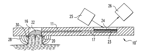
FIGS. 5-8, there is shown an embodiment of the test strip 10' including a
constricting system 27 attached to the underside thereof. The constricting
system
includes several discrete, deformable elements 28, each element defining a
surface
29 to engage the skin and move it inwardly to constrict the skin.
The constricting elements are selected to be spaced apart and to generally
surround the incision site. The elements are therefore preferably provided
such
that at least two elements are positioned to be on opposite sides of the
incision site,
but also any additional number of elements may be included. In a preferred
embodiment, the elements include skin-engaging surfaces 29 positioned to fall
within a circular pattern (FIG. 6). The elements preferably deform in a manner
to
move the skin-engaging surfaces in a radially-inward direction.
The strip 10' otherwise is constructed substantially as shown in FIGS. 1-4,
and is used as follows. The test strip 10' is pressed against the skin such
that the
arms 28 engage the skin and deform inwardly, thereby creating and retaining a
bulged skin area 30. The skin is drawn upward and inward to an extent that it
bears against the sealing member 16, forming a fluid tight seal therewith.
This
assures that any fluid exiting the incision will be retained within the
opening 16,
rather than moving out under the test strip body. The sealing ring further
functions
to pull on the skin, thus opening the incision when formed.
A lancing device 21 is extended downwardly through opening 16 to lance
the skin to the desired, controlled depth. The lancet is then withdrawn (FIG.
8) and
bodily fluid 22 is allowed to form at the incision site. When the fluid
accumulates
to a sufficient extent, it contacts the entrance of the passageway 17 and is
drawn
into and through the passageway to the test area 18.
In another aspect of the present invention, there is provided a test strip
including a surface between the inlet opening and the bottom surface that is
CA 02450114 2003-12-04
WO 02/100278 PCT/US02/18278
13
recessed away from the incision site. By recessing the bottom surface, the
bodily
fluid contacts the inlet opening before it contacts and is drawn along the
bottom
surface.
Referring to the drawings, there is shown a test strip 50 (FIG. 9) in
accordance with another preferred embodiment of the present invention. Test
strip
50 includes a body 51 having first end 52, second end 53, top surface 54 and
bottom surface 55. The body further defines an aperture 56, a test area 57,
and a
sampling passageway 58 communicating with the aperture at an inlet opening 59
spaced from the bottom surface. The sampling passageway extends generally
away from the aperture 56 in the direction of the first end 52.
The test strip is configured to promote contact of the bodily fluid with the
inlet opening 59 prior to making contact with other portions of the test
strip. An
incision is made within the area encompassed by the aperture, and the desire
then
is to cause the bodily fluid coming from the incision to contact the inlet
opening in
preference to any of the surrounding portions of the test strip. In a
preferred aspect
of the present invention, this is accomplished by recessing at least a portion
of the
surface between the inlet opening and the bottom surface. In another aspect,
the
other portions of the bottom surface, for example the portion 60 on the
opposite
side of the aperture, are configured or located to inhibit contact with the
bodily
fluid. In one approach, the incision 61 is formed closer to the side of the
aperture
56 at which the inlet opening is located. In another approach, the test strip
may
also include recessed portions at the other locations surrounding the incision
site.
Accordingly, the test strip 50 includes a recessed surface 62 between the
inlet opening 59 and the bottom surface 55. As used herein, the term "recessed
surface" refers to the surface between the location of the inlet opening and
the
bottom surface. This surface is recessed in the direction away from the
incision
site, i.e., away from the aperture 56 in the direction of the first end 52.
The term
"recess" encompasses any configuration which displaces the closest portion of
the
planar, bottom surface 55 away from the aperture 56. For example, the surface
could be curved inwardly or outwardly, or could have a series of steps of
other
contours.
CA 02450114 2003-12-04
WO 02/100278 PCT/US02/18278
14
As shown in FIG. 9, in a preferred embodiment the test strip includes a
surface 62 which tapers away from the inlet opening 58 to the bottom surface
55.
In this configuration, the surface 62 extends at an obtuse angle 63 from the
bottom
surface. In this embodiment, the surface 62 preferably extends from the bottom
surface at an angle of from about 100 degrees to about 150 degrees, more
preferably from about 120 to about 135 degrees.
The test strip 50 may also include recessed portions at locations away from
the inlet opening. For example, test strip 50 is shown including a recessed
surface
64 on the side of the aperture opposite the inlet opening. Moreover, as shown
more particularly in FIG. 10, the test strip may include a recessed surface
which
completely surrounds the aperture 56, thus providing a frusto-conical surface
on
the underside of the test strip.
The test strip 50 may also include a sealing member (not shown), as
described with respect to FIGS. 1-4. Such a sealing member may be located
along
the recessed surfaces) and/or on the planar, bottom surface. The sealing
member
then complements the action of the recessed surfaces in that bodily fluid that
happens to move against the sealing member will be inhibited from passing
between the test strip and the skin.
The test strip may also be provided with a hydrophobic surface adjacent the
aperture to further inhibit wicking away from the inlet opening. For example,
the
portions of the bottom surface adjacent to the aperture 56 are preferably
provided
with a hydrophobic surface. Further, the recessed surface 62 may be made
hydrophobic to prevent wicking of the bodily fluid toward the bottom surface.
In a
particularly preferred embodiment, the recessed surface includes two different
regions. A first region 65 adjacent the bottom surface is provided to be
hydrophobic to inhibit wicking toward the bottom surface. A second region 66
adjacent the inlet opening is provided to be hydrophilic to promote wicking of
the
bodily fluid toward the inlet opening. Thus, fluid contacting the recessed
surface
will be directed away from the bottom surface and toward the inlet opening.
The test strip 50 is used as follows. The test strip is positioned adjacent to
the skin, either resting against the skin or spaced slightly away from the
skin. If a
CA 02450114 2003-12-04
WO 02/100278 PCT/US02/18278
sealing member is included, then the test strip is placed sufficiently close
to the
skin to have the sealing member contact and seal with the skin. An incision 61
is
formed in the skin 67, and a droplet 68 of bodily fluid forms at the incision
site.
As the droplet grows, it eventually contacts the inlet opening 59 and is drawn
into
5 the passageway 58, such as by capillary action. The recessing of surface 62
causes
the droplet to contact the inlet opening in preference to contacting the
bottom
surface 55, thus avoiding the wicking of bodily fluid between the skin and the
bottom surface. The droplet is precluded from wicking under the test strip in
the
areas away from the inlet opening by locating the incision relatively close to
the
10 inlet opening, and/or by the presence of additional recessed surfaces 64.
The
bodily fluid then moves through the passageway 58 to the test area 57 for
analysis.
An alternate embodiment of the test strip of the present invention is shown
in FIGS. 11 and 12. The test strip 70 includes a body 71 including a first end
72,
second end 73, first side edge 74, second side edge 75, top surface 76 and
bottom
15 surface 77. The test strip 70 further defines a sampling passageway 78
communicating between a test region 79 and an end edge 80 located at the
second
end 73. The sampling passageway 78 includes an inlet opening 81 communicating
with the end edge at a location displaced from the bottom surface 77.
A sealing member 82 is located on the bottom surface 77 in a position to
contact and seal with the skin when the test strip is in use. The sealing
member 82
is aligned under the inlet opening 81 such that bodily fluid present near the
inlet
opening is thereby blocked from passing under the test strip. In one
embodiment,
the sealing member preferably extends from the first edge 74 to the second
edge
75. In an alternate embodiment (not shown), the sealing member extends less
than
the full width of the test strip, or is otherwise configured other than
extending
linearly across the test strip. For example, in one approach the sealing
member
forms a semi-circle contacting the end edge 80 at two locations on either side
of
the inlet opening. In another approach, the sealing member forms a V-shape
extending inwardly of the test strip from the two corners formed between the
end
edge 80 and the two side edges 74 and 75.
CA 02450114 2003-12-04
WO 02/100278 PCT/US02/18278
16
The test strip 70 further includes additional features as described with
respect to the previous embodiments. The test strip includes a recessed
surface 83
connecting between the inlet opening 81 and the bottom surface 77. At least a
lower portion of the recessed surface is preferably provided to be hydrophobic
to
preclude wicking of bodily fluid along the recessed surface toward the
underside of
the test strip. The sealing member 82 and the bottom surface 77 are also
preferably
provided to be hydrophobic to resist wicking of bodily fluid.
The test strip 70 is used in a similar fashion as the previous embodiments.
The test strip is placed adjacent to the skin with the sealing member 82
pressing
against and forming a seal with the skin. The sealing member may be rigid or
deformable in order to provide a suitable seal. The test strip is positioned
with the
inlet opening 81 adjacent to the incision site. The incision is formed either
before
or after placement of the test strip. As the bodily fluid accumulates at the
incision,
it contacts the inlet opening and is drawn into the passageway 78. The
features of
the test strip 70, including the recessed surface 83, the sealing member 82,
and the
provision of hydrophobic surfaces individually and in combination inhibit the
passage of the bodily fluid to the space between the test strip and the skin.
The following embodiments further demonstrate that the sampling systems
are readily adapted for use with various incising, expressing and/or testing
devices.
Referring in particular to FIGS. 13-16, a typical lancing device is shown,
except
that it has been modified to include an exemplary sampling system in
accordance
with the present invention. The basic lancing device, absent the sampling
system,
is further described in United States Patent No. Re 35,803, the disclosure of
which
is hereby incorporated by reference. Therefore, for illustrative purposes,
only the
major components of said device are shown in the drawings and described
herein.
The lancing device 101 includes a housing 102 which contains a lancet
drive mechanism 103 and a lancet holder 104. The drive mechanism includes a
rotatable sleeve 105 and a spirally-wound, coiled spring 106 coupled between
the
housing and the rotatable sleeve. The lancet holder 104 is longitudinally
slidable
within the sleeve 205 and includes arms 107 with end lugs 108 that are
receivable
within recesses formed in a lancet component. The lancet component 109
includes
CA 02450114 2003-12-04
WO 02/100278 PCT/US02/18278
17
a body 110 and a lancet tip 111. The lancet body defines a circumferential
recess
112 which receives the end lugs 108 of the arms of the lancet holder 104. The
lancet 109 is thereby longitudinally movable inside of the sleeve 105 in
concert
with the movement of the lancet holder 104.
The rotatable sleeve 105 includes a drive pin 113, and the lancet holder 104
defines a driver cam 114. The driver cam includes a first cam segment 115 to
allow for cocking of the mechanism. The driver cam further includes a second,
symmetrical, arcuate cam segment 116 to provide for projection and withdrawal
of
the lancet tip relative to the housing opening 117 formed in the pressing
member
118 of the housing. An outer ring 119 connects with the rotatable sleeve 105
and
upon rotation of the outer ring the sleeve is also rotated to tension the
spring 106 as
the drive pin 113 moves within the first cam segment 115. The rotatable sleeve
automatically locks once in the fully tensioned position.
Upon pressing a lock release button 120, the sleeve rotates back to its
original position. During this return rotation, the drive pin 113 moves within
the
second cam segment 116, causing the lancet holder and lancet initially to
translate
longitudinally of the sleeve 105 and housing 102 in a direction to drive the
lancet
tip to incise the skin. The lancet tip 111 is immediately thereafter withdrawn
by
operation of the second cam segment 116 of the lancet holder.
The pressing member extends to an annular surface 121 and defines slots
122 and 123 adjacent thereto. A test strip 124 (FIG. 15) is received within
the slots
122-223 and includes an aperture 125 which is thereby positioned in line with
the
lancet 111. The test strip includes a sealing member 126 forming a ring
surrounding the aperture 125, and further includes a capillary passageway 127
that
extends from an inlet opening which communicates with the aperture 125 to a
test
region 128. The test region includes suitable reagent to interact with the
bodily
fluid which is received in the test region. An optical test device 129 is
mounted to
the housing and is positioned to evaluate the results of the reaction in the
test
region.
In accordance with the present invention, the integrated device 101 is
operable as follows. The device is pressed against the skin 130, which thereby
CA 02450114 2003-12-04
WO 02/100278 PCT/US02/18278
18
bears against the annular surface 121 and the sealing member 126. The lancet
111
is then advanced through the aperture 125 in the test strip and incises the
skin. As
a fluid droplet forms, it contacts the inlet opening of the capillary
passageway 127
and is transported to the test region 128. The fluid then reacts with the
reagent
provided in the test region, and the results are read by the test device 129.
The test
strip may additionally include a recessed surface, as previously described, to
further inhibit the passage of fluid between the skin and the underside of the
test
strip.
The foregoing description provides a representative sample of a lancing
device useful in combination with the test strips of the present invention. It
will be
appreciated, however, that the particular lancing device and method are not
limiting to the present invention, which finds utility with innumerable
lancing
systems. By way of further example, other representative lancing mechanisms
include those shown in United States Patent Nos. 4,924,879, issued to O'Brien
on
May 15, 1990; 5,879,311, issued to Duchon et al. on March 9, 1999; 5,857,983,
issued to Douglas et al. on January 12, 1999; 6,015,392, issued to Douglas et
al. on
January 18, 2000; 6,048,352, issued to Douglas et al. on April 11, 2000;
6,183,489,
issued to Douglas et al. on February 6, 2001; 5,951,492, issued to Douglas et
al. on
September 14, 1999; 5,951,493, issued to Douglas et al. on September 14, 1999;
6,332,871, issued to Douglas et al. on December 25, 2001; 5,964,718, issued to
Duchon et al. on October 12, 1999; 6,066,103, issued to Duchon et al. on May
23,
2000; and 6,086,545, issued to Roe et al. on July 11, 2000.
While the invention has been illustrated and described in detail in the
drawings and foregoing description, the same is to be considered as
illustrative and
not restrictive in character, it being understood that only the preferred
embodiment
has been shown and described and that all changes and modifications that come
within the spirit of the invention are desired to be protected.