Note: Descriptions are shown in the official language in which they were submitted.
CA 02450279 2003-11-19
Device for mixing and dispensing multi-component
compositions
The invention relates to a device for mixing and
dispensing multi-component compositions, in particular
for dental purposes, with a cartridge with at least two
cylindrical chambers arranged in parallel for receiving
the components and in each case a plunger for
discharging the components, the chambers having outlet
openings which are covered by a cap, which has an
outlet tube enclosing a mixing helix, the cap being
movable from a position closing the outlet openings
into a position releasing them.
A known device of this type, which however is not
intended for dental purposes (EP 0 319 135 A2), has two
cylindrical chambers, in each of which one component is
contained. The chambers are provided on their end face
with openings which are closed by a cap. The cap has a
sleeve-shaped outlet tube, which encloses a mixing
helix. The cap initially closes the openings of the
chamber. If the two-component composition is to be
dispensed, the cap is pulled, so that it moves away a
little from the cartridge with the two chambers and
releases the outlet openings. With the aid of plungers
in the chambers, on which pressure is exerted, the
components can then be pressed into the cap and from
there into the sleeve-shaped outlet tube. While
passing through this outlet tube, the components are
mixed by the mixing helix.
Such devices are also very expedient for dental
purposes. There is no need to provide a separate
closure cap that has to be removed and replaced with a
cap which contains the outlet tube and the mixing
helix. However, a disadvantage of such devices is that
a separate manipulation is required for pulling the.cap
to bring it into the open position. This is not only
laborious; there is also the risk of inadvertently
CA 02450279 2011-09-26
-2-
pulling the cap off entirely. Problems also arise in the
production of such already known devices. As far as
possible, the same model of the cartridges is intended to be
supplied with different caps. Depending on the intended
application, straight or curved outlet tubes are required.
These caps must then also be respectively provided with a
mixing helix, making them relatively expensive parts.
Furthermore, the fitting of the mixing helix in the cap is
not entirely simple.
An object of the invention is to provide a device of the
type stated at the beginning which can be operated easily
and unproblematically and allows low-cost and practical mass
production.
The solution according to the invention comprises that the
cap can be moved into the open position by the pressure of
the components while they are being discharged and that a
transverse wall which extends toward the cap and on which
the mixing helix is fitted is provided on the cartridge
between the outlet openings.
According to a further aspect of the invention there is
provided a discharging device comprising a device as
described herein, wherein the discharging device comprises
stop faces which restrict a movement in the discharging
direction, said stop faces being a first stop face for the
cartridge and a second stop face for the cap in the open
state.
More specifically, the present invention provides a device
for mixing and dispensing multi-component compositions, the
device comprising a cartridge having at least two
CA 02450279 2011-09-26
-2a-
cylindrical chambers arranged in parallel for receiving the
components and in each case a plunger for discharging the
components, the chambers having outlet openings which are
covered by a cap, which has an outlet tube enclosing a
mixing helix, the cap being movable from a position closing
the outlet openings into a position releasing them, and a
transverse wall which extends toward the cap and on which
the mixing helix is fitted is provided on the cartridge
between the outlet openings.
In one embodiment, the cap is movable into the open position
by the pressure of the components while they are being
discharged.
There is consequently no longer any need to pull the cap.
Rather, it has an inner surface, opposite from the
cartridge, which is large enough for the pressure of the
components when they are being discharged to move the cap
into the open position. The mixing helix is in this case
fitted on the cartridge and not on the cap. For this
purpose, it is fitted on a transverse wall, which has the
further advantage that the two or more components cannot
easily get into the chamber of the other component
respectively during the dispensing operation, and for example
cause hardening, and consequently make the device unable to
operate.
The cap is expediently rotatable with respect to the
cartridge, since, in the case of a curved outlet tube, the
operator can then set this outlet tube in the way
CA 02450279 2003-11-19
3 -
most expedient for him. However, the rotatability is
only ensured when the cap has been moved into the open
position. For this purpose, with the cap closed, the
transverse wall is enclosed by the cap or is gripped by
it on both sides in such a way that turning is not
possible. As a result, it is possible to form the
inner surface regions of the cap, which are intended to
close the outlet openings of the chambers, optimally
for this purpose.
If the mixing helix is flexible, caps with outlet tubes
that have different curvatures can be used.
The device expediently has latching means for the
closed and open positions. In this case, the latching
means for the closed position must of course be adapted
in its holding force to the opening force produced by
the pressure of the components, in order that the cap
can actually be opened just by pressure exertion and it
does not have to be pulled.
The latching means for the open position expediently
has a greater holding force than the latching means for
the closed position, since otherwise there is the risk
of the cap being detached completely from the cartridge
if, after opening, the operator does not reduce the
force which is required for opening. For this purpose,
it may be provided that the latching means for the open
position is a snap-action latching means, which
provides a greater force of resistance opposing a
further opening movement of the cap than a closing
movement. For this purpose, surfaces which are for
example sawtooth shaped in cross section may be
provided., the sloping surfaces making it easier for the
cap to be pushed onto the cartridge, but the surfaces
perpendicular to the axis then preventing the cap from
being detached when there is a movement in the opposite
direction, that is for pulling off the cap.
CA 02450279 2003-11-19
4 -
Although the device may be designed for more than two
components, it is designed particularly expediently for
two components and correspondingly with two chambers.
The device according to the invention is suitable in
particular for once-only use. It can also be made to
be relatively small and be actuated by a discharging
device or, with the aid of an adapter, by means of a
relatively large pair of grippers. The discharging
device or the adapter may in this case be formed with
surfaces which securely hold the cap, so that the
latter cannot move any further after opening, become
detached from the cartridge and get into the patient's
mouth.
A means 19 for distributing or uniformly
applying/introducing the multi-component composition is
advantageously provided at the outlet end of the outlet
tube 12. This means 19 may be a brush, a small sponge,
a nozzle, a spatula or the like. The means 19 may be
formed as an additional attachment which is attached
onto the outlet tube 12. The means 19 may, however,
also be formed in one piece with the outlet tube 12.
The invention is described below by way of example on
the basis of an advantageous embodiment with reference
to the accompanying drawings, in which, in a
perspective, partly cut-open view:
figure 1 shows the device in the closed state;
figure 2 shows the device, partly cut open, in the
open state;
figure 3 shows detailed views in the section of
the embodiment of figures 1 and 2;
figure 4 shows detailed views of a slightly
different embodiment;
CA 02450279 2003-11-19
- 5 -
figure 5 shows the use of the device according to
the invention in a pair of discharging
grippers with an adapter;
figure 6 shows details in section of the adapter
of figure 5 with the device according to
the invention fitted;
figure 7 shows in section an outlet tube with a
means for distributing the finished
multi-component composition;
figure 8 shows in a perspective view another
embodiment with a means for distributing
the finished multi-component composition;
and
figure 9-20 shows further views and embodiments.
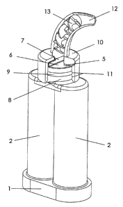
The device of the invention, which is shown in figures
1 and 2, has a cartridge 1, which comprises two
cylindrical chambers 2, arranged in each of which are a
component (not shown) and a plunger 3 (figure 2), by
which pressure can be exerted from the bottom (in the
figures) upward by a suitable implement, in order to
press the components upward through channels 4 and
openings 5. These openings are provided on a circular
surface 6, which is subdivided by a transverse wall 7.
The surface 6 is in this case located on a circular-
cylindrical projection of the cartridge which has an
annular bead 9. Fitted on this cylindrical projection
8 is a cap 10, which has on its inner wall annular
recesses 11, which interact with the annular bead 9.
The cap 10 has a curved outlet tube 12, which encloses
a mixing helix 13, which is fastened on the transverse
wall 7. In the closed state, which is shown in figure
1, the annular bead 9 engages in the upper annular
recess 11 of the cap 10. The substantially circular
inner surface of the cap 10 in this case covers over
CA 02450279 2003-11-19
6 -
the openings 5, so that the chambers 2 are closed. The
transverse wall 7 is securely held against twisting in
a recess 20, which can be seen in figure 2. If
pressure is exerted on the plungers 3, and consequently
the components, the cap is moved by this pressure from
the position shown in figure 1 into the position shown
in figure 2. The cylindrical inner surface of the cap
thereby moves away from the outlet openings 5, so
that the components can emerge. The components are in
10 this case separated from each other by the transverse
wall 7, so that one component cannot readily get into
the chamber 2 of the other component respectively. The
transverse wall 7 is then no longer held by the recess
20, so that the cap 10 can be turned and the operator
can turn the outlet tube 12 into the direction that is
particularly expedient for him.
Figure 3 shows detailed representations of how the cap
10 is securely held with the aid of the annular bead 9
and the recesses 11. At the top it is shown at A that
the annular bead is located in the upper recess 11,
that is to say the cap 10 is assuming its lower
position and closing the openings 5. In the case of
the representation B, the cap has moved upward and is
held in this open position at its lower recess 11 by
the bead 9.
The embodiment of figure 4 differs from that. of figure
3 in that the bead 9 of the cylindrical projection 8 of
the cartridge has a lower straight surface, the lower
recess 11 of the cap 10 likewise having a corresponding-
straight surface. The interaction of these straight
surfaces prevents the cap 10 from being able to move
further upward from the open position shown at B in
figure 4. As a result, flipping off of the cap 10, for
example into the patient's mouth, is prevented.
Shown in figure 5 is an adapter 14, which has an upper
opening into which the cartridge 1 with the cap 10 and
CA 02450279 2003-11-19
7
the outlet tube 12 can be fitted. This adapter 14 may
in turn be fitted onto a pair of grippers 18, which are
intended for other, in particular larger cartridges,
and are commercially available.
Figure 6 shows in section the adapter 14 with the
cartridge 1 fitted. An overall view is shown at A,
detailed views are represented at B and C. In the case
of the position of B in figure 6, the cartridge 1 is
hindered from upward movement at its base part 15 by a
stop face 16 when pressure is exerted on the plungers
3. A further stop face 17 prevents the cap 10 from any
further upwardly directed movement when it moves from
the closed position (at B in figure 6) into the open
position (at C in figure 6). Consequently, this stop
face 17 reliably prevents the cap 10 from being able to
flip off. The adapter has in this case the advantage
that the device according to the invention can also be
used with other commercially available grippers. It
goes without saying that this is not intended to
exclude the possibility of also providing special
grippers for the devices according to the invention,
these grippers then also being covered by the extent of
protection of this patent.
Shown in figure 7 is a cross section through another
embodiment of the outlet tube 12, in which a device 19
is arranged at the outlet end of the same for
distributing or spreading the discharged multi-
component composition. The device 19 for distributing
or spreading can be a brush (figures 7, 8, 9, 10, 17,
18), a small sponge (figure 11), a brush (figure 12), a
nozzle (figures 13, 19, 20), a spatula (figure 14) or a
similar device.
By contrast with the embodiment of figure 7, in the
case of the embodiment of figure 8 the means 19 for
distributing the finished multi-component composition
onto the outlet tube 12 has been fitted, so that
CA 02450279 2003-11-19
g _
various parts 19 can optionally be fitted here on the
outlet tube 12. This is shown also in the embodiment of
figures 15 and 16.