Note: Descriptions are shown in the official language in which they were submitted.
CA 02450432 2003-12-10
WO 02/101191 PCT/US02/18500
-1-
PACKING ASSEMBLY FOR ROTARY DRILLING SWIVELS
BACKGROUND OF THE INVENTION
FIELD OF THE INVENTION
The present invention relates to packing assemblies for use in effecting fluid
sealing around the wash pipe of a rotary drilling swivel.
DESCRIPTION OF THE PRIOR ART
In the drilling of oil and gas wells, a drill bit is rotated in a borehole by
means of
a string of drill pipe. The drill pipe is rotated on the surface mechanically
by a rotating
table mounted on a drilling platform or by a hydraulic motor, commonly
referred to as
a top drive. As is common in such oil and gas well drilling, drilling fluid or
inud is
circulated through the drill pipe and the drill bit to cool the drill bit and
remove the
cuttings, which are then recirculated to the surface and removed from the
drilling fluid
so it can be reused. Particularly in the case of deep wells, the drilling
fluid can be at
pressures that can range to several thousand psi.
The rotary drilling swivel commonly used in the drilling of oil and gas wells
provides rotating support for the drill string suspended from it and a sealed
passageway
for circulating drilling fluids into the drill string. The drill pipe is in
open-flow
communication with a wash pipe, through which the drilling fluid flows, the
wash pipe
usually being stationary. A packing assembly forming part of the swivel
rotates with the
drill pipe, and is in sealing engagement with the wash pipe to prevent loss of
drilling
fluid out of the swivel assembly.
As noted above, depending on the depth of the well and/or well condition,
drilling
fluid pressure can reach several thousand psi, and at these high pressures,
conventional,
prior art packing assemblies used to seal between the wash pipe and the rotary
head to
which the drill pipe is secured have reduced life, resulting in leaking.
Additionally, in
top drive applications wherein the swivel assembly is rotating at a height of
from 50 to
60 feet a.bove the rig floor during drilling, it is difficult to maintain or
adjust the packing
or to add lubrication to the packing. Accordingly, only periodically, and
typically only
once a day, will the drilling operation be stopped to allow some adjustment to
the rotating
CA 02450432 2003-12-10
WO 02/101191 PCT/US02/18500
-2-
packing assembly and/or the addition of lubricant, which can be added through
a grease
port in the portion of the gland of the packing assembly that contains the
seal rings.
SUMMARY OF THE INVENTION
In a preferred embodiment of the present invention, there is provided a
packing
assembly for use in sealing around the wash pipe of a drilling swivel, the
packing
assembly including a housing forming a sealing assembly chamber and a sealing
assembly disposed in the chamber. The sealing assembly is comprised of at
least one
annular seal ring which sealingly engages the wash pipe. A containment member
which
is axially spaced from the seal ring and an injectable packing positioned
between the seal
ring and the containment member and sealingly engaging the wash pipe. An
injection
port or the like is provided to permit injection of the injectable packing
into the chamber
between the seal ring and the containment member.
CA 02450432 2003-12-10
WO 02/101191 PCT/US02/18500
-3-
BRIEF DESCRIPTION OF THE DRAWINGS
1. Fig. 1 is an elevational view, partly in sections, showing a prior art
packing assembly used in a rotary drilling swivel;
2. Fig. 2 is a figure similar to Fig. 1 showing one embodiment of the packing
assembly according to.the present invention;
3. Fig 3 is a view similar to Fig. 1 showing another embodiment of the
packing assembly of the present invention; and
4. Fig 4 is a view similar to Fig. 1 showing another embodiment of the
paclcing assembly of the present invention.
CA 02450432 2006-12-06
-4-
DETAILED DESGR3PTION OF PREFERRED EMBODI1ViENTS
Referri.ng, first, to Fig. 1, there is shown a rotary drilling swivel with a
conventional, prior art packing assembly. The swivel assembly, shown generally
as (10),
is shown in simplified form, dxilling swivels of the type under consideration
being well
known to those skilled in the art. The swivel. (10) includes a goose neck head
(12) having
an inlet (14) connected to a source of drilling fluid (not shown). Inlet (14)
is in
communication with a flow passage (16) which, in turn, is in open
comm.uni.cation with
a wash pipe (18), through which d.ri.lling fluid flows in the direction shown
by anrow A.
'Ifireadedly connected to goose neck. head (12) is gland (20). Gland (20)
defines a
chamber (22) in which is received a collar (24) in surrounding relationship to
wash pipe
(18). A series of set screws (26) received in threaded bores in collar (24)
engage bores
(28) in wash pipe (18) whereby wash pipe (18) is .fixedly connected to and
remains
stationary with goose neck head (12). An 0-ring seal (30) provides fluid tight
sealing
bet-vveen collar (24) and goose neck head (12) while a lip type seal (32)
insures fluidtight
sealing between wash pipe (18) and collar (24).
Wash. pipe (18) is in open communication with a threaded opening (34) in a
rotating head (36), rotating head (36), rotating head (36) being part of a top
drive
assembly well known to those slcilled in the art as sliown, for example, in
U.S. Patent
4,449,596, which may be referred to for further details.
A rotating packing assembly, shown gener.ally as (40) includes a threaded
gland
(42) received on the neck portion (44) ofrotating head (36). Gland (42) forms
an annular
sealing assembly chamber (46) in surroundin.g relationship to wash pipe (18).
As is
conventional in these prior art packing assemblies, there are a series of
axially spaced
annular lip seals (48) which in conjunction with metal adapter rings (50, 52
and 54)
maintain seal rings (48) in sealing engagement,"dtli wash pipe (18) as packing
assembly
(40) rotates around. wash pipe (18). An O-ring seal (56) provide static
sealing bet"*een
metal adapter (54) and the neck (44) of rotating head (36). As is also
conventional in
prior art paclcing assemblies such as packing assembly (40), there is a port
(58) through
the wall of gland (42) whi.cli is provided with a button head fitting (60)
which permits a
lubricant to be injected into chamber (46).
Refening now to Fig. 2, there is shown one embodiment of the packing assembly
of the present invention. Save for the constniction of the packing assembly,
described
CA 02450432 2003-12-10
WO 02/101191 PCT/US02/18500
-5-
hereafter, the embodiment shown in Fig. 2 is essentially the same as that
shown in Fig.
1. Packing assembly (40a) includes a sealing assembly shown generally as (64)
which
is disposed in a chamber (46a) formed by gland (42a). Sealing assembly (64)
includes
a first lip type seal ring (48) having an axially extending portion (48a)
received in an
annular recess (66) formed in gland (42a), seal (48) being in sealing
engagement with
wash pipe (18). Seal ring (48) is held in position by a generally L-shaped
annular metal
adapter (68) which essentially forms an annular pocket in which is received
seal ring
(48). A second metal adapter ring (70), in cooperation with metal adapter ring
(68),
forms an annulus (72) around wash pipe (18). Adapter ring (70) includes an
annular
axially projection flange portion (70a) and an annular radially inwardly
projecting lip
(70b). Metal adapter (70) in cooperation with another metal adapter (74)
cooperate to
form a pocket for a second type seal ring (48) which is in sealing engagement
with wash
pipe (18), seal ring (48) engaging one side of lip (70b). Injection port (58)
in gland (42a)
is in register with a port (76) in metal adapter ring (68) which in turn opens
into annulus
(72). Disposed in annulus (72) is an injectable packing (80) described more
fully
hereafter, injectable packing (80) being introduced into annulus (72) via
injector head
(82) received in bore (58). As can be seen, the injectable packing (80) fills
annulus (72)
and because of its malleable nature, forms a seal between wash pipe (18) and
adapter
rings (70) and (68). Additionally, as can be seen, a portion of injectable
packing (80)
engages the uppermost seal ring (48). Further, because of its malleable
nature, packing
(80) will also flow past lip (70b) to engage seal ring (48) which engages lip
(70b).
Referring to Fig. 3, there is shown yet another embodiment of the packing
assembly of the present invention. Packing assembly (40b) differs from packing
assembly (406a) in that the sealing assembly, shown generally as (90), is of
the cartridge
type. A gland (42b) secured to head (36) forms a sealing assembly chamber
(46b).
Sealing assembly (90), received in chamber (46b), includes a casing formed by
cylindrical wall portion (92) from which projects radially inwardly, an
annular flange
(94). Sealing between cylindrical wall (92) and gland (42a) is accomplished by
means
of 0-rings (93). As can be seen, flange (94) has an axial projection (96)
which nests in
recess (98) in gland (42a). The end (100) of the casing distal flange (94)
engages metal
adapter ring (102), cylindrical wall (92) and flange (94) serving to form an
annulus (104)
between wash pipe (18) and cylindrical wall (92). Disposed in the annulus
(104) are first
CA 02450432 2003-12-10
WO 02/101191 PCT/US02/18500
-6-
and second type chevron type seal rings (106), rings (106) being axially
spaced as shown,
one of the chevron rings (106) engaging a backup ring (107) which in turn
engages flange
(94), the other of the chevron ring (106) engaging a backup ring (109) wliich
engages
metal adapter (102). The annular, axially extending space between the chevron
rings
(106) is filled with an injectable packing (110) which can be introduced via
injection
assembly (82) and port (58), there being a registering port (112) in
cylindrical wall (92).
It will be appreciated that chevron rings (106) are in sealing engagement with
wash pipe
(18) and cylindrical wall (92), injectable packing (110) likewise being in
sealing
engagement with wash pipe (18) and cylindrical wall (92). Additionally, and
because of
the malleable nature of injectable packing (110),. the radially imler and
radially outermost
lips of the chevron seal rings (106) will effectively be pressure energized by
injectable
packing (110) enhancing their sealing effectiveness.
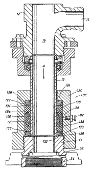
Turning now to Fig. 4, there is shown another embodiment of the packing
assembly of the present invention. Packing assembly (40c) includes a gland
(42c)
forming an annular chamber (46c) in surrounding relationship to wash pipe
(18).
Disposed in chamber (46c) is a sealing assembly shown generally as (120).
Sealing
assembly (120) includes an upper, metal adapter ring (122) which engages the
end wall
of gland (42c), sealing between metal adapter (122) and gland (42c) being
affected by 0-
rings (124) and (126). In like fashion, a second metal adapter ring (128) is
axially
displaced from metal adapter (122) and is sealed against gland (42c) and the
neck (44)
of rotating head (36) by means of seal rings (130) and (132), respectively. A
first backup
or anti-extrusion ring (134) engages metal adapter (126) while a second backup
or anti-
extrusion ring (136) engages metal adapter ring (128). First and second
axially spaced
chevron type seal rings (138) are received in chamber (46c), one of the
chevron type seal
rings (138) engaging in the anti-extrusion ring (134), the other of the
chevron type seal
rings (138) engaging in extrusion ring (136). The annular, axially extending
space
between the chevron rings (138) is filled with injectable packing (140)
introduced via
injection assembly (82) and port (58). It can be seen that the chevron rings
(138) as well
as injectable packing (140) are in sealing engagement with wash pipe (18) as
well as
gland (42c). As is the case with the embodiments shown in Fig. 3, the
injectable packing
(140), because of its malleable nature, pressure energizes the chevron seals
(138) forcing
CA 02450432 2003-12-10
WO 02/101191 PCT/US02/18500
-7-
the radially innermost and radially outermost sealing lips into fluid tight
engagement with
the wash pipe (18) and gland (42c), respectively.
The injectable packing employed in the packing assemblies of the present
invention is of a type that is malleable and has a putty like consistency,
meaning that it
is injectable or pumpable in the sense that it can be forced via a
hydraulically activated
injection gun or the like into a space between two relatively movable members,
and,
when in the space can conform to the surfaces forining the space to effect
fluid type
sealing between the two relatively movable members. Such inj ectable packings
generally
have at least two main components: a carrier and a filler. Generally
spealcing, the carrier
comprises greases, oil and other such viscous lubricants while the filler can
include a
wide variety of synthetic and natural materials which can be in the form of
fibers, flocks,
particles or the like. Such fillers can include, without limitation, glass
fibers, carbon
fibers, araa.nid fibers, polybenzimidazole fibers, boron fibers, graphite
fibers, PTFE
particles, etc. In general, the filler should be of a material which is non-
abrasive so as
to prevent any wearing or galling of moving parts which contact the injectable
packing.
The injectable packing employed in the packing assemblies of the present
invention can
be tailored to meet various pressure and temperature applications. For
example, an
injectable packing suitable for use in the present invention can be blend of
exfoliated
graphite particles and high temperature sacrificial lubricants. A suitable
injectable
packing for use in the packing assembly of the present invention is marketed
under the
trademark UPAK 2000ES by Utex Industries, Inc. As noted above, these
injectable
packings can be injected into the packing assembly by way of a hydraulically
operated
injection gun or the like. The injectable packings of the present invention
remain
malleable indefinitely and, accordingly, additional inj ectable packing can be
added to the
packing assemblies of the present invention as wear occurs. Because the
injectable
packings are of such a highly viscous nature, they do not easily extrude past
packing
rings such as the type noted above and conventionally used in packing
assemblies of the
type under consideration.
Ideally, the injectable packing is pressured up to a pressure which, when the
drilling operation commences is more or less the same as the pressure of the
drilling fluid
meaning that the seal rings are in a substantially balanced pressure state.
Accordingly,
the packing rings are subjected to less work and exhibit longer life than do
conventional
CA 02450432 2003-12-10
WO 02/101191 PCT/US02/18500
-8-
packing rings. Preferably, the injectable packings of the present invention
would
generally be of a type that possess high thermal conductivity, to aid in heat
dissipation
which again enhances the working life of the seal rings.
While the invention has been described above with respect to a rotary drilling
swivel in which the wash pipe is stationary and the packing assembly is
rotating, it is to
be understood that the packing assembly is applicable to those cases wherein
the wash
pipe is rotating and the packing assembly is stationary.