Note: Descriptions are shown in the official language in which they were submitted.
CA 02450463 2003-12-11
WO 02/101648 PCT/US02/18960
APPARATUS AND METHOD FOR WATERMARKING A
DIGITAL IMAGE
BACKGROUND OF THE INVENTION
I. Field of the Invention
[0001] The present invention relates to a method and apparatus for
watermarking a
digital image. The invention may be usefully employed in the newly emerging
field
of digital cinema.
II. Description of the Related Art
[0002] In the traditional film industry, theatre operators receive reels of
celluloid' film
from a studio or through a distributor for eventual presentation in a theatre
auditorium. The reels of film include the feature program (a full-length
motion
picture) and a plurality of previews and other promotional material, often
referred to
as trailers. This approach is well established and is based in technology
going back
around one hundred years.
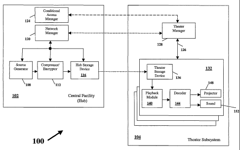
[0003] Recently an evolution has started in the film industry, with the
industry
moving from celluloid film to digitized image and audio programs. Many
advanced
technologies are involved and together those technologies are becoming known
as
digital cinema. It is planned that digital cinema will provide a system for
delivering
full length motion pictures, trailers, advertisements and other audiovisual
programs
comprising images and sound at "cinema-quality" to theatres throughout the
world
using digital technology. Digital cinema will enable the motion picture cinema
industry to convert gracefully from the century-old medium of 35mm film into
the
digital/wireless communication era of today. This advanced technology will
benefit
all segments of the movie industry.
[0004] The intention is that digital cinema will deliver motion pictures that
have been
digitized, compressed and encrypted to theatres using either physical media
distribution (such as DVD-ROMs) or electronic transmission methods, such as
via
satellite multicast methods. Authorized theatres will automatically receive
the
CA 02450463 2003-12-11
WO 02/101648 PCT/US02/18960
2
digitized programs and store them in hard disk storage while still encrypted
and
compressed. At each showing, the digitized information will be retrieved via a
local
area network from the hard disk storage, be decrypted, decompressed and then
displayed using cinema-quality electronic projectors featuring high quality
digital
sound.
[0005] Digital cinema will encompass many advanced technologies, including
digital
compression, electronic security methods, network architectures and
management,
transmission technologies and cost-effective hardware, software and integrated
circuit
design. The technologies necessary for a cost-effective, reliable and secure
system
are being analyzed and developed. These technologies include new forms of
image
compression, because most standard compression technologies, such as MPEG- 2,
are
optimized for television quality. Thus, artifacts and other distortions
associated with
that technology show up readily when the image is projected on a large screen.
Whatever the image compression method adopted, it will affect the eventual
quality
of the projected image. Special compression systems have therefore been
designed
specifically for digital cinema applications to provide "cinema-quality"
images at bit
rates averaging less than 40 Mbps. Using this technology a 2-hour movie will
require
only about 40 GB of storage, making it suitable for transportation on such
media as
so-called digital versatile disks (DVDs) or transmission or broadcast via a
wixeless
link.
[0006] While this has obvious advantages in terms of the distribution of
movies, it
brings with it its own problems in that in itself such transportation and
transmission is
not secure. Encryption and conditional access methods are therefore also being
developed with the aim of preventing piracy of movies. In addition to digital
theft,
i.e., the theft of a pristine digital copy of the content of the DVDs and/or
transmitted
data, there is also the problem of optical theft. Optical theft is the
recording of the
image and audio content of a movie as it is being projected onto the screen of
a
theater. Optical theft is easy to perform using, for example, little more than
a
camcorder.
CA 02450463 2003-12-11
WO 02/101648 PCT/US02/18960
SUMMARY OF THE INVENTION
[0007] While there is no sure way of preventing digital or optical theft, it
is possible
to reduce the likelihood of it occurring by increasing the probability of the
perpetrators of the theft being caught. The invention addresses the above-
discussed
problems associated with digital cinema and is useful in overcoming or at
least
reducing the problem of digital and optical theft. To this end the invention
aims to
provide a method and apparatus for inserting an imperceptible watermark or
"digital
fingerprint" into the image content. The watermark preferably indicates at
least one
of the location, date and time of showing of the movie, thereby enabling the
location
date and time of the theft to be determined.
[0008] Although the foregoing introduction and following description
concentrate on
the insertion of a watermark into an image as the movie is being shown
(thereby
enabling both optical and digital theft at the theater to be tracked), it will
be
appreciated by those possessed of the appropriate skills that the same
technique could
equally well be used in a telecine when original film is converted into
digital form
(thereby enabling digital and optical theft outside the theater to be
tracked). The
watermark might for example identify any one or, more of the location, date
and time
of creation of the digital version of the film, the film owner's identity, or
copyright
information. The technique is applicable to still images as well as moving
images.
[0009] According to one aspect of the invention, there is provided an
apparatus for
applying data representing a watermark to data representing an image, the
apparatus
comprising: a source of location and time data; an error coding unit connected
to
receive the location and time data for applying a forward error correction
algorithm to
the said location and time data and outputting error coded data therefrom; a
code
spreading unit connected to receive the error coded data for spreading the
error coded
data to create spread data by repeatedly outputting portions of the error
coded data a
number of times therefrom; a DES code generator for generating and outputting
data
representing a DES code; a combiner for combining the spread data and the DES
code
and outputting watermark data representing a location and time specific
watermark; a
receiver for receiving signals containing said data representing an image as
DCT
coefficients in transform space, which data is received in an encoded and
compressed
CA 02450463 2003-12-11
WO 02/101648 PCT/US02/18960
4
form on a signal medium, and for receiving an apparatus specific key; a
decoding
circuit responsive to the apparatus specific key for decoding and
decompressing the
received signals to recover the data representing an image therefrom; a
control circuit
for analyzing at least a component of the image data to determine an attribute
thereof
and to output a signal representative of the attribute; a marking control
unit,
connected to receive the signal from the control circuit, the image data from
the
source and the watermark data from the combiner, for adding the watermark data
to
the image data depending on a characteristic of the attribute and a
characteristic of the
image data; an inverse DCT transform circuit connected to receive the
watermarked
image data and to convert the same from data representing the image as DCT
coefficients in transformation space to data representing the image in pixel
space; a
pixel processor connected to receive the data representing the image in pixel
space for
converting the pixel data into a format suitable for display; and a projector
connected
to receive formatted pixel data from the pixel processor for projecting the
image
represented thereby.
[0010] According to another aspect of the invention there is provided an
apparatus for
applying data representing a watermark to data representing an image, the
apparatus
comprising: means for supplying location and time data; means for receiving
the
' location and time data, for applying error coding to the said location and
time data,
and outputting error coded data therefrom; spreading means connected to
receive the
error coded data for applying a spreading function to the error coded data and
outputting spread data therefrom; means for generating and outputting data
representing a pseudo-random code; means for combining the spread data and the
pseudo-random code and outputting watermark data representing a location and
time
specific watermark; means for supplying image data representing an image in
transformation space; means for analyzing at least a component of the image
data to
determine an attribute thereof and for outputting a signal representative of
the
attribute; and marking means, connected to receive the signal representative
of the
attribute, the image data and the watermark data, for adding the watermark
data to the
image data depending on a characteristic of the attribute and a characteristic
of the
image data.
CA 02450463 2003-12-11
WO 02/101648 PCT/US02/18960
[0011] According to a further aspect of the invention there is provided a
method of
applying data representing a watermark to data representing an image, the
method
comprising: supplying location and time data; applying a forward error
correction
algorithm to the said location and time data to produce error coded data;
applying a
spreading function to the error coded data to create spread data by repeating
portions
of the error coded data a number of times; generating data representing a DES
code;
combining the spread data and the DES code to create watermark data
representing a
location and time specific watermark; receiving signals containing said data
representing an image as DCT coefficients in transform space, which data is
received
in an encoded and compressed form on a signal medium; receiving an apparatus
specific key; decoding and decompressing the received signals responsive to
the
apparatus specific key to recover the data representing an image therefrom;
analyzing
at least a component of the image data to determine an attribute thereof and
to create a
signal representative of the attribute; adding the watermark data to the image
data
depending on a characteristic of the attribute and a characteristic of the
image data;
and converting the watermarked image data from data representing the image as
DCT
coefficients in transformation space to data representing the image in pixel
space;
converting the pixel data into a format suitable for display; and projecting
the image
represented by the formatted pixel data.
[0012]. According to another aspect of the invention there is provided a
method of
applying data representing a watermark to data representing an image, the
method
comprising: supplying location and time data; applying error coding to the
said
location and time data to produce error coded data; applying a spreading
function to
the error coded data to produce spread data; generating data representing a
pseudo-
random code; combining the spread data and the pseudo-random code to produce
watermark data representing a location and time specific watermark; supplying
image
data representing an image in transformation space; analyzing at least a
component of
the image data to determine an attribute thereof to produce a signal
representative of
the attribute; and adding the watermark data to the image data depending on a
characteristic of the attribute and a characteristic of the image data.
[00I3] The invention also provides an apparatus for adding a watermark to a
moving
image as it is displayed, the apparatus comprising: a watermark generator in
which
CA 02450463 2003-12-11
WO 02/101648 PCT/US02/18960
6
data representing a watermark is generated containing first information
pertaining to
the displaying of the moving image and protected by forward error encoding and
second information pertaining to the displaying of the moving image and
protected by
scrambling; and a watermark applicator for applying the watermark data to
image data
representing substantially all of the moving image depending on a
characteristic of the
data.
[00I4] The invention further provides a watermarking system for applying data
representing a moving image to produce watermarked image data which is output
to a
display device for display of the moving image represented thereby, in which
system
information identifying at least one of the system, the image and the
displaying of the
image is convolutionally encoded and spread and information identifying at
least one
of the system, the image and the displaying of the image is encrypted so as to
produce
the watermark data which is applied to substantially all data representing the
moving
image with the exception of data having a value below a determined level in
order to
minimize the introduction of visible noise and other artifacts into the image
by the
watermark.
BRIEF DESCRIPTION OF THE DRAWINGS
[0015] The above and further features of the invention are set forth with
particularity
in the appended claims and together with advantages thereof will become
clearer from
consideration of the following detailed description of an exemplary embodiment
of
the invention given with reference to the accompanying drawings, in which:
[0016] Figure 1 illustrates a block diagram of a digital cinema system;
[0017] Figure 2 is a block diagram of a compressor/encryptor circuit used in
the
system of Figure 1;
[0010 Figure 3 illustrates an auditorium module used in the system of Figure
1;
[0019] Figure 4 is a block diagram representing parts of an
encryptionldecryption unit
for applying watermarks to image data;
[0020] Figure 5 is a block diagram representing a watermark unit of the
encryption/decryption unit of Figure 4.; and
[0021] Figure 6 is a block diagram representing a theater manager and its
associated
interfaces used in the system of Figure 1.
CA 02450463 2003-12-11
WO 02/101648 PCT/US02/18960
7
DETAILED DESCRIPTION OF AN EMBODIMENT OF THE INVENTION
[0022] The following description is intended to provide both an overview of a
digital
cinema system in which the invention may be embodied and a detailed disclosure
of
the presently preferred embodiment itself. Systems similar to the system shown
herein are described extensively in other applications assigned to the
assignee of this
application, including USSN 09/564,174, entitled, "Apparatus And Method For
Encoding And Storage Of Digital Image And Audio Signals" and USSN 09/563,880,
entitled, "Apparatus And Method For Decoding Digital Image And Audio Signals"
both filed May 3, 2000, the teachings of which are incorporated herein by
reference.
[0023]' A digital cinema system 100 embodying the invention is illustrated in
Figure 1
of the 'accompanying drawings. The digital cinema system 100 comprises two
main
systems: 'at least one central facility or hub 102 and at least one
presentation or theater
subsystem 104. The hub 102 and the theater subsystem 104 are of a similar
design to
that of pending US Patent Application Serial No. 09/075,152, filed on May 8,
1998,
assigned to the same assignee as the present invention, the teachings of which
are
incorporated herein by reference.
[0024] Image and audio information are compressed and stored on a storage
medium,
and distributed from the hub 102 to the theater subsystem 104. Generally, one
theater
subsystem 104 is utilized for each theater or presentation location in a
network of
presentation locations that is to receive image or audio information, and
includes
some centralized equipment as well as certain equipment employed for each
presentation auditorium.
[0025] In the central hub 102, a source generator 108 receives film material
and
generates a digital version of the film. The digital information is compressed
and
encrypted by a compressor/encryptor (CE) 112, and stored on a storage medium
by a
hub storage device 116. A network manager 120 monitors and sends control
information to the source generator 108, the CE 112, and the hub storage
device 116.
A conditional access manager 124 provides specific electronic keying
information
such that only specific theaters are authorized to show specific programs.
[0026] In the theater subsystem 104, a theater manager 12S controls an
auditorium
module 132. Based on control information received from the auditorium module
132,
CA 02450463 2003-12-11
WO 02/101648 PCT/US02/18960
8
a theater storage device 136 transfers compressed information stored on the
storage
medium to a playback module 140, The playback module 140 receives the
compressed information from the theater storage device 136, and prepares the
compressed information to a predetermined sequence, size and data rate. The
playback module 140 outputs the compressed information to a decoder 144. The
decoder 144 inputs compressed information from the playback module 140 and
performs decryption, decompression and formatting, and outputs the information
to a
projector 148 and a sound module 152. The projector 148 plays the information
on a
projector and the sound module 152 plays sound information on a sound system,
both
under control of the auditorium module 132.
[0027] In operation, the source generator 108 provides digitized electronic
image
and/or programs to the system. Typically, the source generator 108 receives
film
material and generates a magnetic tape containing digitized information or
data. The
film is digitally scanned at a very high resolution to create the digitized
version of the
motion picture or other program. Typically, a known "telecine" process
generates the
image information while well-known digital audio conversion processing
generates
the audio portion of the program. The images being processed need not be
provided
from a film, but can be single picture or still frame type images, or a series
of frames
or pictures, including those shown as motion pictures of varying length. These
images can be presented as a series or set to create what are referred to as
image
programs. In addition, other material can be provided such as visual cue
tracks for
sight-impaired audiences, subtitling for foreign language and/or hearing
impaired
audiences, or multimedia time cue tracks. Similarly, single or sets of sounds
or
recordings are used to form desired audio programs.
[0028] Alternatively, a high definition digital camera or other known digital
image
generation device or method may provide the digitized image information. The
use of
a digital camera, which directly produces the digitized image information, is
especially useful for live event capture for substantially immediate or
c~ntemporaneous distribution. Computer workstations or similar equipment can
also
be used to directly generate graphical images that are to be distributed.
[0029] The digital image information or program is presented to the
compressor/encryptor 112, which compresses the digital signal using a
preselected
CA 02450463 2003-12-11
WO 02/101648 PCT/US02/18960
9
known format or process, reducing the amount of digital information necessary
to
reproduce the original image with very high quality. Preferably, an ABSDCT
technique is used to compress the image source. A suitable ABSDCT compression
technique is disclosed in U.S. Pat. Nos. 5,021,891, 5,107,345, and 5,452,104,
the
teachings of which are incorporated herein by reference. The audio information
may
also be digitally compressed using standard techniques and may be time
synchronized
with the compressed image information. The compressed image and audio
information is then encrypted andlor scrambled using one or more secure
electronic
methods.
[0030] The network manager I20 monitors the status of compressor/encryptor
1I2,
and directs the compressed information from the compressor/encryptor 112 to
the hub
storage device 116. The hub storage device 116 is comprised-of one or more
storage.
The storage medium/media may be any type of high capacity data storage device
including, but not limited to, one or more digital versatile disks (DVDs) or
removable
hard drives (RHDs). Upon storage of the compressed information onto the
storage
medium, the storage medium is physically transported to the theater subsystem
I04,
and more specifically, to the theater storage device 136.
[0031] Alternatively, the compressed image and audio information may each be
stored in a non-contiguous or separate manner independent of each other. That
is, a
means is provided for compressing and storing audio programs associated with
image
information or programs but segregated in time. There is no requirement to
process
the audio images at the same time. A predefined identifier or identification
mechanism or scheme is used to associate corresponding audio and image
programs
with each other, as appropriate. This allows linking of one or more
preselected audio
programs with at least one preselected image program, as desired, at a time of
presentation, or during a presentation event. That is, while not initially
time
synchronized with the compressed image information, the compressed audio is
linked
and synchronized at presentation of the program.
j0032] Further, maintaining the audio program separate from the image program
allows for synchronizing multiple languages from audio programs to the image
program, without having to recreate the image program for each language.
Moreover,
maintaining a separate audio program allows for support of multiple speaker
CA 02450463 2003-12-11
WO 02/101648 PCT/US02/18960
configurations without requiring interleaving of multiple audio tracks with
the image
program.
[0033] In addition to the image program and the audio program, a separate
promotional program, or promo program, may be added to the system. Typically,
promotional material changes at a greater frequency than the feature program.
Use of
a separate promo program allows promotional material to be updated without
requiring new feature image programs. The promo program comprises information
such as advertising (slides, audio, motion or the like) and trailers shown in
the theater.
Because of the high storage capacity of storage media such as DVDs and RHDs,
thousands of slides or pieces of advertising may be stored. The high storage
volume
allows for customization, as specific slides, advertisements or trailers may
be shown
at specific theaters to targeted customers.
[0034]= Although Figure 1 illustrates the compressed information in the
storage device
116 and physically transporting storage medium/media to the theater subsystem
104,
it should be understood that the compressed information, or portions thereof,
may be
transmitted to the theater storage device 136 using any of a number wireless
or wired
transmission methods. Transmission methods include satellite transmission,
well-
known mufti-drop, Internet access nodes, dedicated telephone lines, or point-
to-point
fiber optic,networks.
[0035]. A block diagram of the compressor/encryptor 112 is illustrated in
Figure 2 of
the accompanying drawings. Similar to the source 'generator 108, the
compressor/encryptor 112 may be part of the central hub 102 or located in a
separate
facility. For example, the compressor/encryptor 112 may be located with the
source
generator 108 in a film or television production studio. In addition, the
compression
process for either image or audio information or data may be implemented as a
variable rate process.
[0036] The compressor/encryptor 112 receives a digital image and audio
information
provided by the source generator 108. The digital image and audio information
may
be stored in frame buffers (not shown) before further processing. The digital
image
signal is passed to an image compressor 184. In a preferred embodiment, the
image
compressor 184 processes a digital image signal using the ABSDCT technique
described in the abovementioned U.S. Pat. Nos. 5,021,891, 5,107,345, and
5,452,104.
CA 02450463 2003-12-11
WO 02/101648 PCT/US02/18960
11
[0037] In the ABSDCT technique, the color input signal is generally in a YIQ
format,
with Y being the luminance, or brightness, component, and I and Q being the
chrominance, or color, components. Other formats such as the YUV, YCbCr, or
RGB
formats may also be used. Because of the low spatial sensitivity of the eye to
color,
the ABSDCT technique sub-samples the color (I and Q) components by a factor of
two in each of the horizontal and vertical directions. Accordingly, four
luminance
components and two chrominance components are used to represent each spatial
segment of image input. The ABS DCT Technique also supports a format called
4:4:4 where no nonsampling of chrominance component takes place. Pixels in
each
component are represented digitally in up to 10 bits linear or log scale.
[0038] ~ Each of the luminance and chrominance components is passed to a block
interleaver. Generally, a 16x16 block is presented to the block interleaver,
which
orders the image samples within the 16x16 blocks to produce blocks and
composite
sub-blocks of data for discrete cosine transform (DCT) analysis. The DCT
operator is
one method of converting a time-sampled signal to a frequency representation
of the
same signal.. By converting to a frequency representation, the DCT techniques
have
been shown to allow for very high levels of compression, as quantizers can be
designed to take advantage of the frequency distribution characteristics of an
image.
Preferably, one 16x16 DCT is applied to a first ordering, four 8x8 DCTs are
applied
to a second ordering, 16 4x4 DCTs are applied to a third ordering, and 64 2x2
DCTs
are applied to a fourth ordering.
[0039] The DCT operation reduces the spatial redundancy inherent in the image
source. After the DCT is performed, most of the image signal energy tends to
be
concentrated in a few DCT coefficients.
[0040] For the 16x16 block and each sub-block, the transformed coefficients
are
analyzed to determine the number of bits required to encode the block or sub-
block.
Then, the block or the combination of sub-blocks, which requires the least
number of
bits to encode, is chosen to represent the image segment. For example, two 8x8
sub-
blocks, six 4x4 sub-blocks, and eight 2x2 sub-blocks may be chosen to
represent the
image segment.
[0041] The chosen block or combination of sub-blocks is then properly arranged
in
order. The DCT coefficient values may then undergo further processing such as,
but
CA 02450463 2003-12-11
WO 02/101648 PCT/US02/18960
12
not limited to, frequency weighting, quantization, and coding (such as
variable length
coding) using known techniques, in preparation for transmission. The
compressed
image signal is then provided to at least one image encryptor 188.
[0042] The digital audio signal is generally passed to an audio compressor
192.
Preferably, the audio compressor 192 processes multi-channel audio information
using a standard digital audio compression algorithm. The compressed audio
signal is
provided to at least one audio encryptor 196. Alternatively, the audio
information
may be transferred and utilized in an uncompressed but still digital, format.
[0043]~ The image encryptor 188 and the audio encryptor 196 encrypts the
compressed image and audio signals, respectively, using any of a number of
known
encryption techniques. The image and audio signals may be encrypted using the
same
or different techniques. In a preferred embodiment, an encryption technique,
which
comprises real-time digital sequence scrambling of both image and audio
programming, is used.
[0044] At the image and audio encryptors 188.and 196, the programming material
is
processed by a scrambler/encryptor circuit that uses time-varying electronic
keying
information (typically changed several times per second). The scrambled
program
information can then be stored or transmitted, such as over the air in a
wireless link,
without being decipherable to anyone who does not possess the associated
electronic
keying information used to scramble the program material or digital data.
[0045] Encryption generally involves digital sequence scrambling or direct
encryption
of the compressed signal. The words "encryption" and "scrambling" are used
interchangeably and are understood to mean any means of processing digital
data
streams of various sources using any of a number of cryptographic techniques
to
scramble, cover, or directly encrypt said digital streams using sequences
generated
using secret digital values ("keys") in such a way that it is very difficult
to recover the
original data sequence without knowledge of the secret key values.
[0046] Each image or audio program may use specific electronic keying
information
which is provided, encrypted by presentation-location or theater-specific
electronic
keying information, to theaters or presentation locations authorized to show
that
specific program. The conditional access manager (CAM) 124 handles this
function.
The encrypted program key needed by the auditorium to decrypt the stored
CA 02450463 2003-12-11
WO 02/101648 PCT/US02/18960
13
information is transmitted, or otherwise delivered, to the authorized theaters
prior to
playback of the program. Note that the stored program information may
potentially
be transmitted days or weeks before the authorized showing period begins, and
that
the encrypted image or audio program key may be transmitted or delivered just
before
the authorized playback period begins. The encrypted program key may also be
transferred using a low data rate link, or a transportable storage element
such as a
magnetic or optical media disk, a smart card, or other devices having erasable
memory elements. The encrypted program key may~also be provided in such a way
as
to control the period of time for which a specific theater complex or
auditorium is
authorized to show the program.
[0047] Each theater subsystem 104 that receives an encrypted program key
decrypts
this value using its auditorium specific key, and stores this decrypted
program key in
a memory device or other secured memory. When the program is to be played
back,
the theater or location specific and program specific keying information is
used,
preferably with a symmetric algorithm, that was used in the encryptor 112 in
preparing the encrypted signal to now descramble/decrypt program information
in
real-time.
[0048] Returning now to Figure 2, in addition to scrambling, the image
encryptor 188
may add a "watermark" or "fingerprint" which is usually digital in nature, to
the
image programming. This involves the insertion of a location specific and/or
time
specific visual identifier into the program sequence. That is, the watermark
is
constructed to indicate the authorized location and time for presentation, for
more
efficiently tracking the source of illicit copying when necessary. The
watermark may
be programmed to appear at frequent, but pseudo-random periods in the playback
process and would not be visible to the viewing audience. The watermark is
perceptually unnoticeable during presentation of decompressed image or audio
information at what is predefined as a normal rate of transfer. However, the
watermark is detectable when the image or audio information is presented at a
rate
substantially different from that normal rate, such as at a slower "non-real-
time" or
still frame playback rate. If an unauthorized copy of.a program is recovered,
the
digital watermark information can be read by authorities, and the theater from
which
CA 02450463 2003-12-11
WO 02/101648 PCT/US02/18960
14
the copy was made can be determined. Such a watermark technique may also be
applied or used to identify the audio programs.
[0049]- The compressed and encrypted image and audio signals are both
presented to a
multiplexer 200. At the multiplexer 200, the image and audio information is
multiplexed together along with time synchronization information to allow the
image
and audio-streamed information to be played back in a time aligned manner at
the
theater subsystem 104. The multiplexed signal is then processed by a program
packetizer 204, which packetizes the data to form the program stream: By
packetizing the data, or forming "data blocks," the program stream may be
monitored
during decompression at the theater subsystem 104 (see Figure 1) fox errors in
receiving the blocks during decompression. Requests may be made by the theater
manager 128 of the theater subsystem 104 to acquire data blocks exhibiting
errors.
Accordingly, if errors exist, only small portions of the program need to be
replaced,
instead of an entire program. Requests of small blocks of data may be handled
over a
wired or wireless link. This provides for increased reliability and
efficiency.
[0050] Alternatively, the image and audio portions of a program are treated as
separate and distinct programs. Thus, instead of using the multiplexer 200 to
multiplex the image and audio signals, the image signals are separately
packetized. In
this way the image program may be transported exclusive of the audio program,
and
vice versa. As such, the image and audio programs are assembled into combined
programs only at playback time. This allows for different audio programs to be
combined with image programs for various reasons, such as varying languages,
providing post-release updates or program changes, to fit within local
community
standards, and so forth. This ability to flexibly assign audio different mufti-
track
programs to image programs is very useful for minimizing costs in altering
programs
already in distribution, and in addressing the larger mufti-cultural markets
now
available to the film industry.
[0051] The compressors 184 and 192, the encryptors 188 and 196, the
multiplexer
200, and the program packetizer 204 may be implemented by a
compression/encryption module (CEM) controller 208, a software-controlled
processor programmed to perform the functions described herein. That is, they
can be
configured as generalized function hardware including a variety of
programmable
CA 02450463 2003-12-11
WO 02/101648 PCT/US02/18960
electronic devices or computers that operate under software or firmware
program
control. They may alternatively be implemented using some other technology,
such
as through an ASIC or through one or more circuit card assemblies, i.e.,
constructed
as specialized hardware.
[0052] The image and audio program stream is sent to the hub storage device
116.
The CEM controller 208 is primarily responsible for controlling and monitoring
the
entire compressor/encryptor 112. The CEM controller 208 may be implemented by
programming a general-purpose hardware device or computer to perform the
required
functions, or by using specialized hardware. Network control is provided to
CEM
controller 208 from the network manager 120 (Figure 2) over a hub internal
network,
~as described herein. The CEM controller 208 communicates with the compressors
184 and 192, the encryptors 188 and 196, the multiplexer 200, and the
packetizer 204
using a known digital interface and controls the operation of these elements.
The
CEM controller 208 may also control and monitor the storage module 116, and
the
data transfer between these devices.
[0053] ~ The storage device 116 is preferably constructed as one or more RHDs,
DVDs
disks or other high capacity storage medium/media, which in general is of
similar
design as the theater storage device 116 in theater subsystem 104. However,
those
skilled in the art will recognize that in some applications other media may be
used
including but not limited to DVDs (Digital Versatile Disks) or so-called JBODs
("Just
a Bunch Of Drives"). The storage device 116 receives the compressed arid
encrypted
image, audio, and control data from the program packetizer 204 during the
compression phase. Operation of the storage device 116 is managed by the CEM
controller 208.
[0054] Figure 3 of the accompanying drawings illustrates operation of the
auditorium
module 132 using one or more RHDs (removable hard drives) 308. For speed,
capacity, and convenience reasons, it may be desirable to use more than one
RHD
308a to 308n. When reading data sequentially, some RHDs have a "prefetching"
feature that anticipates a following read command based upon a recent history
of
commands. This prefetching feature is useful in that the time required to read
sequential information off the disk is reduced. However, the time needed to
read non-
sequential information off the disk may be increased if the RHD receives a
command
CA 02450463 2003-12-11
WO 02/101648 PCT/US02/18960
16
that is unexpected. In such a case, the prefetching feature of the RHD may
cause the
random access memory of the RHD to be full, thus requiring more time to access
the
information requested. Accordingly, having more than one RHD is beneficial in
that
a sequential stream of data, such as an image program, may be read faster.
Further,
accessing a second set of information on a separate RHD disk, such as audio
programs, trailers, control information, or advertising, is advantageous in
that
accessing such information on a single RHD is more time consuming.
[0055] Thus, compressed information is read from one or more RHDs 308 into a
buffer 284. The FIFO-RAM buffer 284 in the playback module 140 receives the
portions of compressed information from the storage device 136 at a
predetermined
rate. The FIFO-RAM buffer 284 is of a sufficient capacity such that the
decoder 144,
and subsequently the projector 148, is not overloaded or under-loaded with
information. Preferably, the FIFO-RAM buffer 284 has a capacity of about 100
to
200 MB. Use of the FIFO-RAM buffer 284 is a practical necessity because there
may
be a several second delay when switching from one drive to another.
[0056] The portions of compressed information is output from the FIFO-RAM
buffer
into a network interface 288, which provides the compressed information to the
decoder 144. Preferably, the network interface 288 is a fiber channel
arbitrated loop
(FC-AL) interface. Alternatively, although not specifically illustrated, a
switch
network controlled by the theater manager 128 receives the output data from
the
playback module 140 and directs the data to a given decoder 144. Use of the
switch
network allows programs on any given playback module 140 to be transferred to
any
given decoder 144.
[0057] When a program is to be viewed, the program information is retrieved
from
the storage device 136 and transferred to the auditorium module 132 via the
theater
manager 128. The decoder 144 decrypts the data received from the storage
device
136 using secret key information provided only to authorized theaters, and
decompresses the stored information using the decompression algorithm which is
inverse to the compression algorithm used at source generator 108. The decoder
144
includes a converter (not shown in Figure 3) which converts the decompressed
image
information to an image display format used by the projection system (which
may be
either an analog or digital format) and the image is displayed through an
electronic
CA 02450463 2003-12-11
WO 02/101648 PCT/US02/18960
17
projector 148. The audio information is also decompressed and provided to the
auditorium's sound system 152 for playback with the image program.
[0058]. - The decoder 144 will now be described in greater detail by further
reference to
Figure 3. The decoder 144 processes a compressedlencrypted program to be
visually
projected onto a screen or surface and audibly presented using the sound
system 152.
The decoder 144 comprises a controlling CPU (central processing unit) 312,
which
controls the decoder. Alternatively, the decoder may be controlled via the
theater
manager 128. The decoder further comprises at least one depacketizer 316, a
buffer
314, an image decryptor/decompressor 320, and an audio decryptor/decompressor
324. The buffer may temporarily store information for the depacketizer 316.
All of
the above-identified units of the decoder 144 may be implemented on one or
more
circuit card assemblies. The~circuit card assemblies may be installed in a
self
contained enclosure that mounts on or adjacent to the projector 148.
Additionally, a
cryptographic smart card 328 may be used which interfaces with controlling CPU
312
and/or image decryptor/decompressor 324 for transfer and storage of unit-
specific
cryptographic keying information.
[0059] . The depacketizer 316 identifies and separates the individual control,
image,
and audio packets that arrive from the playback module 140, the CPU 312 andlor
the
theater manager 128. Control packets may be sent to the theater manager 128
while
.the image and audio packets are sent to the image and audio
decryption/decompression systems 320 and 324, respectively. Read and write
operations tend to occur in bursts. Therefore, the buffer 314 is used to
stream data
smoothly from the depacketizer 316 to the projection equipment.
[0060] The theater manager 128 configures, manages the security of, operates,
and
monitors the theater subsystem 104. This includes the external interfaces,
image and
audio decryption/decompression modules 320 and 324, along with projector 148
and
the sound system module 152. Control information comes from the playback
module
140, the CPU 312, the theater manager system 128, a remote control port, or a
local
control input, such as a control panel on the outside of the auditorium module
132
housing or chassis. The decoder CPU 312 may also manage the electronic keys
assigned to each auditorium module x32. Pre-selected electronic cryptographic
keys
assigned to auditorium module 132 are used in conjunction with the electronic
CA 02450463 2003-12-11
WO 02/101648 PCT/US02/18960
18
cryptographic key information that is embedded in the image and audio data to
decrypt the image and audio information before the decompression process.
Preferably, the CPU 312 uses a standard microprocessor running embedded in the
software of each auditorium module 132, as a basic functional or control
element.
[0061] In addition, the CPU 312 is preferably configured to work or
communicate
certain information with theater manager 128 to maintain a history of
presentations
occurring in each auditorium. Information regarding this presentation history
is then
available for transfer to the hub 102 using the return link, or through a
transportable
medium at preselected times.
[0062] The image decryptor/decompressor 320 takes the image data stream from
depacketizer 316, performs decryption, adds a watermark and reassembles the
original
image for presentation on the screen. The output of this operation generally
provides
standard analog RGB signals to digital cinema projector 148. Typically,
decryption
and decompression are performed in real-time, allowing for real-time playback
of the
programming material.
[0063] The image decryptorldecompressor 320 decrypts and decompresses the
image
data stream to reverse the operation performed by the image compressor 184 and
the
image encryptor 188 of the hub 102. Each auditorium module 132 may process and
display a:different program from other auditorium modules 132 in the same
theater
subsystem 104 or one or more auditorium modules 132 may process and display
the
same program simultaneously. Optionally, the same program may be displayed on
multiple projectors, the multiple projectors being delayed in time relative to
each
other.
[0064] The decryption process uses previously provided unit-specific and
program-
specific electronic cryptographic key information in conjunction with the
electronic
keys embedded in the data stream to decrypt the image information. Each
theater
subsystem 104 is provided with the necessary cryptographic key information for
all
programs authorized to be shown on each auditorium module 132.
[0065] A multi-level cryptographic key manager is used to authorize specific
presentation systems for display of specific programs. This multi-level key
manager
typically utilizes electronic key values which are specific to each authorized
theater
manager 128, the specific image and/or audio program, and/or a time varying
CA 02450463 2003-12-11
WO 02/101648 PCT/US02/18960
19
cryptographic key sequence within the image and/or audio program. An
"auditorium
specific" electronic key, typically 56 bits or longer; is programmed into each
auditorium module 132.
[00G6] This programming may be implemented using several techniques to
transfer
and present the key information for use. For example, the return link
discussed above
may be used through a link to transfer the cryptographic information from the
conditional access manager 124. Alternatively, smart card technology such as
smart
card 328, pre-programmed flash memory cards, and other known portable storage
devices may be used.
[0067] . For example, the smart card 328 may be designed so that this value,
once
loaded into the card, cannot be read from the smart card memory.
[006]. . Physical and electronic security measures are used to prevent
tampering with
this key information and to detect attempted tampering or compromise. The key
is
. stored in such a way that it can be erased in the event of detected
tampering attempts.
The smart card circuitry includes a microprocessor core including a software
implementation of an encryption algorithm, typically Data Encryption Standard
(DES). The smart card can input values. provided to it, encrypt (or decrypt)
these
values using the on-card DES algorithm and the pre-stored auditorium specific
key,
and output the result. Alternatively, the smart card 328 may be used simply to
transfer encrypted electronic keying information to circuitry in the theater
subsystem
104 which would perform the processing of this key information for use by the
image
and audio decryption processes.
[0069] Image program data streams undergo dynamic image decompression using an
inverse ABSDCT algorithm or other image decompression process symmetric to the
image compression used in the central hub compressor/encryptor 112. If image
compression is based on the ABSDCT algorithm the decompression process
includes
variable length decoding, inverse frequency weighting, inverse quantization,
inverse
differential quad-tree transformation, mCT, and DCT block combiner
deinterleaving.
The processing elements used for decompression may be implemented in dedicated
specialized hardware configured for this function such as an ASIC or one or
more
circuit card assemblies. Alternatively, the decompression processing elements
may be
implemented as standard elements or generalized hardware including a variety
of
CA 02450463 2003-12-11
WO 02/101648 PCT/US02/18960
digital signal processors or programmable electronic devices or computers that
operate under the control of special function software or firmware
programming.
Multiple ASICs may be implemented to process the image information in parallel
to
support high image data rates.
[0070] Digital watermarks are applied to the image data before the image is
output for
display by the projector. The watermarks are applied by the image
decryptor/decompressor 320 before the data is output to the projector 148 for
display
of the image that it represents.
[0071] Referring now to Figure 4 of the accompanying drawings, relevant parts
of the
decryptor/decompressor 320 for applying a watermark to the image are shown
therein.
The decryptor/decompressor 320 comprises a compressed data interface (CDI)
401,
which receives the depacketised, compressed and encrypted data from the
depacketiser 316 (see Figure 3). Data tends to be moved around and processed
in
bursts, and so the received data is stored in a random access store 402, which
is
preferably an SDRAM device or similar, until it is needed. The data input to
the
SDRAM store 402 corresponds to compressed and encrypted versions of the image
data. The store 402, therefore, need not be very large (relatively speaking)
to be able
to store data corresponding to a large number of image frames.
[0072] From time to time, the data is taken from the store 402 by the CDI 401
and
output to a decryption circuit 403 where it is decrypted using a DES (Data
Encryption
Standard) key. The DES key is specific to the encryption performed at the
central
facility 102 (see Figure 1) and, therefore, enables the incoming data to be
decrypted.
The data may also be compressed before it is transmitted from the central
facility,
using lossless techniques including Huffman or run-length encoding and/or
lossy
techniques including block quantization in which the value of the data in a
block is
divided by a power of 2 (i.e., 2 or 4 or 8, etc). The decryptorldecompressor
320 thus
comprises a decompressor, e.g., an inverse quantization block (Huffman/IQB)
decompressor 404 that decompresses the decrypted data. The decompressed data
from the Huffman/IQB decompressor 404 represents the image data in the DCT
domain.
[0073] Since the system already comprises the necessary hardware and software
to
effect DCT compression techniques, specifically the above-mentioned ABSDCT
CA 02450463 2003-12-11
WO 02/101648 PCT/US02/18960
21
compression technique, to compress data, the same is used to embed a
watermarlc into
the picture in the DCT domain. Other transformations could, of course, be used
but
since the hardware is already there in the system this offers the most cost-
effective
solution.
[0074] Data from the decompressor 404 is, therefore, input to a watermark
processor
40S where a watermark is applied in a manner that will be described in greater
detail
herein below. The data from the watermark processor 405 is then input to an
inverse
DCT transforming circuit 406 where the data is converted from the DCT domain
into
image data' in the pixel domain.
[0075] The thus produced pixel data is input to a frame buffer interface 407
and
associated SDRAM store 408. The frame buffer interface 407 and associated
store
408 serves as a buffer in which the pixel data is held for reconstruction in a
suitable
format for display of the image by a pixel image processor 409. The SDRAM
store
408 may be of a similar size to that of the SDRAM store 402 associated with
the
compressed data interface 401. However, since the data input to the frame
buffer
interface 407 represents the image in the pixel domain, data for only a
comparatively
small number of image frames can be stored in the SDRAM store 408. This is not
a
problem because the purpose of the frame buffer interface 407 is simply to
reorder the
data from the inverse DCT circuit and present it for reformatting by the pixel
image
processor.409 at the display rate.
[0076] The decompressed image data goes through digital to analog conversion,
and
the analog signals are output to projector 148 for display of the image
represented by
the image data. The projector 148 presents the electronic representation of a
program
on a screen. The high quality projector is based on advanced technology, such
as
liquid crystal light valve (LCLV) methods for processing optical or image
information. The projector 148 receives an image signal from image
decryptor/decompressor 320, typically in standard Red-Green-Blue (RGB) video
signal format. Alternatively, a digital interface may be used to convey the
decompressed digital image data to the projector 148 obviating the need for
the
digital-to-analog process. Information transfer for control and monitoring of
the
projector 148 is typically provided over a digital serial interface from the
controller
312.
CA 02450463 2003-12-11
WO 02/101648 PCT/US02/18960
22
[0077] Figure 5 of the accompanying drawings shows the watermark processor 405
in
greater detail. The watermark processor 405 is a configurable coefficient
modulator
in which registers store the watermark identification information and
decisions are
made on which reels to mark and how heavily.
[0078] The watermark processor 405 embeds an imperceptible projector
identification
code and time stamp into consecutive frames of video before the data is output
to the
projector for display. This identification coding is able to withstand basic
image
manipulations such as resolution scaling and cropping. More involved attacks,
such
as inter-frame averaging, collusion of segments from multiple sources, and
image
warping, are possible but beyond the resources of the casual video pirate. The
watermarking information is inserted into the video data in such a way that
all
information contained in the watermark is readable during any contiguous
segment of
the motion image program of no more than five minutes in duration.
[0079]' The watermark processor 405 employs a DES engine that is keyed to the
program key. This serves three purposes. Firstly, the watermark pattern cannot
be
predicted because the sequence is tied to a non-linear noise generator.
Secondly, the
watermark is specific to the individual program and ensures the' pirate cannot
tamper
with it, despite having compromised another program or being aware of the
watermark technique. Thirdly, the watermark is imperceptible because it is
masked in
a noise-like random sequence, i.e., the code generated by the DES engine.
[0080] It is assumed that a video pirate will know that the movie material he
is
stealing will contain a watermark of some origin. He may not be able to
perceive it or
strip it from the image, but he may be able to alter it using some or all of
the
following methods.
[0081] Basic manipulations such as resolution scaling and cropping occur when
the
program is recorded onto a video camera or similar device. The digital cinema
display format can be as large as 2560 x 1088; most consumer equipment is
limited to
a maximum of 800 x 600 pixels (SVHS). This implies a resolution scaling
operation
and possibly also a cropping operation. The video pirate may decide to capture
the
entire width of the image (letterbox format) or a fraction of it (pan and
scan).
[0082] Complex manipulations such as inter-frame averaging occur when two
video
frames from the same scene are used to average out the areas that have been
CA 02450463 2003-12-11
WO 02/101648 PCT/US02/18960
23
watermarked. One form of this inter-frame averaging could occur when the
charge-
coupled device (CCD) in a video camera converts the 24 or 30 fps of the
projector
into its internal refresh rate.
[0083] Another complex manipulation attack can occur when the same program
sequence is captured from different projectors with different watermark
identification
codes. The sets of frames can be compared to identify which portions of a
frame are
marked and average those out. A variation on this scheme, collusion, uses two
copies
of the program to identify marked portions and then modifies them to fabricate
a false
signature of a third copy. A further complex manipulation, image warping,
involves
using a geometric transformation on every frame. Under this scheme, image bits
are
moved slightly to new positions so that the image appears untouched, but the
watermark detector cannot locate the bits.
[0084] The watermark processor 405 comprises a number ofregisters 421 to 425
that
hold variables used in the watermarking process. Registers 421 and 422 hold
data
respectively identifying the projector (which one and in which theatre) and
the time of
display of the program. The projector identity data and the time stamp data
are input
to an error correction unit 427 where forward error correction, i.e.,
convolutional
coding, is applied. The error corrected data from the correction unit 427 is
input to a
spreading block 429 together with a spreading factor from the register 423.
The
spreading block 429 spreads the bits from the correction unit 427 so as to
make the
watermarking data more robust against short-period manipulations. The
spreading
function performed by the spreading block 429 may, for example, duplicate each
input bit a number of times before moving on to the next bit. This enables the
data to
be spread within a frame with the code changing on a frame-by-frame basis, or
to be
spread over several frames with the code changing after a predetermined number
of
frames.
[0085] The watermark processor 405 also comprises a DES engine 432. The DES
engine 432 generates DES codes entirely independently of the DES codes used by
the
DES decryption unit 403 (see Figure 4). The DES key used by the DES decryption
unit 403 pertains to the encryption and decryption of the data.from the
central facility
(see Figure 1) whereas the DES key generated by the DES engine 432 is specific
to
the theater and/or the projector I which the movie is displayed.
CA 02450463 2003-12-11
WO 02/101648 PCT/US02/18960
24
[0086] The DES engine 432 is used to generate a pseudo-random noise (PN)
sequence for embedding the watermark data into the movie bits. A program lcey
is
loaded from register 424 into the DES engine 432 at the start of the program
and used
throughout the program. At the beginning of each frame, the initial vector is
loaded
with the current frame number. The DES engine 432 is configured in output
feedback
mode. In this manner, a long-period PN sequence is generated that is unique
for
every frame of every program. The thus generated long PN sequence is output to
an
exclusive-OR (XOR) combiner 433 where it is combined on a bit-by-bit basis
with
the data from the spreading block 429.
[0087] ~ .. An amplitude control block 434 identifies the level at which each
DCT
coefficient is marked. Amplitude control is accomplished by determining the
magnitude of each DCT coefficient and using the magnitude of the DCT
coefficients
to index data in a look-up table. The magnitude of he coefficient is
determined as
loge of .the absolute coefficient value. The DCT transform domain has the
advantage
that watermarks are adaptable because the strength of the watermark depends on
the
intensity values of the DCT coefficients of the original image. -The watermark
is
made strong in the DCT coefficients with large intensity values and is
attenuated in '.
areas with small DCT values.
[0088] Although any color component may be used, Figure 5 illustrates only DCT
coefficients for the luminance (Y) component of the image are input to the
amplitude
control block 434 (and indeed to the watermark processor 405). In this
embodiment,
the DCT coefficients relating to the color different components (CR and CB) of
the
image bypass the watermark processor 405 entirely. This is because the color
difference components (CR and CB) by themselves cannot be used to produce a
meaningful image but the luminance (Y) .component may be used to create a
black-
and-white version of the image. Processing the DCT coefficients for the Y
component reduces processing overheads. In another embodiment, the CR and/or
CB
components are input to the watermark processor.
[0089] The amplitude control block 434 produces an amplitude value that is
passed to
a marking control block 436. The marking control block 436 controls the actual
selection of the components to mark. It decides which DCT coefficients are
marked
and in what types of sub-blocks. Any block size (16x16, 8x8, 4x4, 2x2) may be
CA 02450463 2003-12-11
WO 02/101648 PCT/US02/18960
marked, whether the block is deemed perceptually significant or not. In an
embodiment, both perceptually significant and other blocks are marked. In
another .
embodiment, perceptually significant blocks are not marked. The marking
control
block 436 converts the watermark value from the XOR combiner 433 into a
negative
value (-1) if the watermark bit is a zero (0) and into a positive value (+I)
if the
watermark bit is a one (I): The marking control block 436 also decides whether
or
not the watermark data will actually be incorporated into the DCT coefficients
for the
luminance component. To this end the marking control block examines the value
of
the coefficient and/or the amplitude value from the amplitude control block
together
with other information (including block.size) pertaining to the DCT
coefficients.
Generally, watermarking is not applied to coefficients whose loge value is
zero since .
this may introduce a noise into the image. Such noise would probably be
visible in
the image and is therefore unacceptable. When watermarking is to be applied
the
positive (+1) or negative (-1) value is added to the luminance (Y) data.
[0090] The data output from the marking control block 436 are input to an
adder 438
where they are added to the DCT coefficients for the luminance component of
the
image. In this way, the watermark data is applied to the image data while
still in the
DCT domain. Apart from the DC components, all DCT coefficients are
considered'as
candidates for the application of watermark data. The data is applied
depending on
r among other things the amplitude of a coefficient. The application of
watermarking
data to a DCT coefficient will have an effect on an area in the image since
each DCT
coefficient contributes to several pixels in the image. It follows, therefore,
that the
watermarking is applied to substantially the whole of the image and not just
selected
portions of it. This tends to make the watermarking more robust to such
attacks as
those discussed herein above.
[0091] Those possessed of the appropriate skills will appreciate from the
foregoing
that the watermark is constructed to indicate the authorized location and time
for
presentation, for more efficiently tracking the source of illicit copying when
necessary. The watermark may appear at frequent, but deterministic periods in
the
playback process and is not visible to the viewing audience. The watermark is
perceptually unnoticeable during presentation of decompressed image or audio
information at what is predefined as a normal rate of transfer. However, the
CA 02450463 2003-12-11
WO 02/101648 PCT/US02/18960
26
watermark may be detectable, although not perceptible, when the image or audio
information is presented at a rate substantially different from that normal
rate, such as
at a slower "non-real-time" or still frame playback rate. If an unauthorized
copy of a
program is recovered, the digital watermark information can be read by
authorities,
and the theater from which the copy was made can be determined.
[0092] The watermarked DCT data thus produced by the watermarking processor
405
is input to the inverse DCT unit 406 where it is converted into pixel data as
has
already been explained herein with reference to Figure 4. Thus, the
decryptor/decompressor 320 serves to decrypt the incoming data, decompress it,
apply
a watermark, convert the data from the DCT domain to the pixel.domain and
reconstruct the pixels into a suitable format for display of the image by the
projector
148.
[0093] The audio decryptor/decompressor 324 shown in Figure 3 operates in a
similar
manner on the audio data, although it does not apply data representing a
watermark or
fingerprint to the audio signal. Of course such a watermark technique may also
be
applied or used to identify the audio programs, if desired. The audio
decryptor/decompressor 324 takes the audio data stream from the depacketizer
316,
performs decryption, and reassembles the original audio for presentation on a
theater's speakers or audio sound system 152. The output of this operation
provides
standard line level audio signals to the sound system 152.
[0094] Similar to the image decryptor/decompressor 320, the audio
decryptor/decompressor 324 reverses the operation performed by the audio
compressor 192 and the audio encryptor 196 of the hub 102. Using electronic
keys
from the cryptographic smart card 32$ in conjunction with the electronic keys
embedded in the data stream, the decryptor 324 decrypts the audio information.
The
decrypted audio data is then decompressed.
[0095] Audio decompression is performed with an algorithm symmetric to that
used
at the central hub 102 for audio compression. Multiple audio channels, if
present, are
decompressed. The number of audio channels is dependent on the mufti-phonic
sound system design of the particular auditorium, or presentation system.
Additional
audio channels may be transmitted from the central hub 102 for enhanced audio
programming for purposes such as mufti-language audio tracks and audio cues
for
CA 02450463 2003-12-11
WO 02/101648 PCT/US02/18960
27
sight impaired audiences. The system may also provide additional data tracks
synchronized to the image programs for purposes such as multimedia special
effects
tracks, subtitling, and special visual cue tracks for hearing impaired
audiences.
[0096] As discussed earlier, audio and data tracks may be time synchronized to
the
image programs or may be presented asynchronously without direct time
synchronization. Image programs may consist of single frames (i.e., still
images), a
sequence of single frame still images, or motion image sequences of short or
long
duration.
[0097] : If necessary, the audio channels are provided to an audio delay
element, which
inserts a delay as needed to synchronize the audio with the appropriate image
frame.
Each channel then goes through a digital to analog conversion to provide what
are
known as "line level" outputs to sound system 152. That is, the appropriate
analog
level or format signals are generated from the digital data to drive the
appropriate
sound system. The line level audio outputs typically use standard XLR or
AES/EBU
connectors found in most theater sound systems.
[0098] Referring back to Figure 3, the decoder chassis 144 includes a fiber
channel
interface 288, the depacketizer 316, the decoder controller or CPU 312, the
image
decryptor/decompressor 320, the audio decryptor/decompressor 324, and the
cryptographic smart card 328. The decoder chassis 144 is a secure, self-
contained
chassis that also houses the encryption smart card 328 interface, internal
power supply
and/or regulation, cooling fans (as necessary), local control panel, and
external
interfaces. The local control panel may use any of various known input devices
such
as a membrane switch flat panel with embedded LED indicators. The local
control
panel typically uses or forms part of a hinged access door to allow entry into
the
chassis interior fox service or maintenance. This door has a secure lock to
prevent
unauthorized entry, theft, or tampering of the system. During installation,
the smart
card 328 containing the encryption keying information (the auditorium specific
key)
is installed inside the decoder chassis 144, secured behind the locked front
panel. The
cryptographic smart card slot is accessible only inside the secured front
panel. The
YIQ signal output from the image decryptor/decompressor 320 to the projector
148 is
connected securely within the decoder chassis 144 in such a way that the YIQ
signals
cannot be accessed while the decoder chassis 144 is mounted to the projector
housing.
CA 02450463 2003-12-11
WO 02/101648 PCT/US02/18960
28
Security interlocks may be used to prevent operation of the decoder 144 when
it is not
correctly installed to the projector 148.
[0099] The sound system 1S2 presents the audio portion of a program on the
theater's
speakers: Preferably, the sound system 1S2 receives up to 12 channels of
standard
format audio signals, either in digital or analog format, from the audio
decryptor/decompressor 324.
[0100] Alternatively, the playback module 144 and the decoder 144 may be
integrated
into a single playback-decoder unit 132. Combining the playback module 140 and
the
decoder module 148 results in cost and access time savings in that only a
single CPU
(292 or 312) is needed to serve the functions of both the playback module 140
and the
decoder 144. Combination of the playback module 140. and the decoder 144 also
does
not require the use of a fiber channel interface 288.
[0101] . If multiple viewing locations are desired, information on any storage
device
136 is configured to transfer compressed information of a single image program
to
different auditoriums with preselected programmable offsets or delays in time
relative
to each other. These preselected programmable offsets are made substantially
equal
to zero or very small when a single image program is to be presented to
selected
multiple auditoriums substantially simultaneously. At other times, these.
offsets can
.be set anywhere from a few minutes to several hours, depending on the storage
configuration and capacity, in order to provide very flexible presentation
scheduling.
This allows a theater complex to better address market demands for
presentation
events such as first run films.
[0102) The theater manager 128 is illustrated in greater detail in Figure 6 of
the
accompanying drawings. Turning now to Figure 6, the theater manager 128
provides
operational control and monitoring of the entire presentation or theater
subsystem
104, or one or more auditorium modules 132 within a theater complex. The
theater
manager 128 may also use a program control means or mechanism for creating
program sets from one or more received individual image and audio programs,
which
are scheduled for presentation on an auditorium system during an authorized
interval.
[0103] The theater manager 128 comprises a theater manager processor 336 and
may
optionally contain at least one modem 340, or other device that interfaces
with a
return link, for sending messages back to central hub 102. The theater manager
128
CA 02450463 2003-12-11
WO 02/101648 PCT/US02/18960
29
may include a visual display element such as a monitor and a user interface
device
such as a keyboard, which may reside in a theater complex manager's office,
ticket
booth, or any other suitable location that is convenient for theater
operations.
[0104] The theater manager processor 336 is generally a standard commercial or
business grade computer. The theater manager processor 336 communicates with
the
network manager 120 and conditional access manager 124 (see Figure 1).
Preferably,
the modem 340 is used to communicate with the central hub 102. The modem 340
is
generally a standard phone line modem that resides in or is connected to the
processor, and connects to a standard two-wire telephone Line to communicate
back to
the central~hub 102. Alternatively, communications between the theater manager
processor 336 and the central hub 102 may be sent using other low data rate
communications methods such as Internet, private or public data networking,
wireless, or satellite communication systems. For these alternatives, the
modem 340
is configured to provide the appropriate interface structure.
[0I05] The theater manager 128 allows each auditorium module 132 to
communicate
with each storage device 136. A theater management module interface may
include a
buffer memory such that information bursts may be transferred at high data
rates from
the theater storage device 136 using the theater manager interface 126 and
processed
at slower rates by other elements of the auditorium module 132.
[0106] . Information communicated between the theater manager 128 and the
network
manager 120 and/or the conditional access manager.124 include requests for
retransmission of portions of information received by the theater subsystem
104 that
exhibiting uncorrectable bit errors, monitor and control information,
operations
reports and alarms, and cryptographic keying information. Messages
communicated
may be cryptographically protected to provide eavesdropping type security
and/or
verification and authentication.
[0107] The theater manager 128 may be configured to provide fully automatic
operation of the presentation system, including control of the
playback/display,
security, and network management functions. The theater manager 128 may also
provide control of peripheral theater functions such as ticket reservations
and sales,
concession operations, and environmental control. Alternatively, manual
intervention
may be used to supplement control of some of the theater operations. The
theater
CA 02450463 2003-12-11
WO 02/101648 PCT/US02/18960
34
manager 128 may also interface with certain existing control automation
systems in
the theater complex for control or adjustment of these functions. The system
to be
used will depend on the available technology and the needs of the particular
theater,
as would be known.
[0108] Through either control of theater manager 128 or the network manager
120,
the invention generally supports simultaneous playback and display of recorded
programming on multiple display projectors. Furthermore, under control of
theater
manager 128 or the network manager 120, authorization of a program for
playback
multiple times can often be done even though theater subsystem 104 only needs
to
receive the programming once. Security management may control the period of
time
and/or the number of playbacks that are allowed for each program.
[0109] ' . Through automated control of the theater manager 128 by the network
management module 112, a means is provided for automatically storing, and
presenting programs. In addition, there is the ability to control certain
preselected
network operations from a location remote from the central facility using a
control
element. For example, a television or film studio could automate and control
the
distribution of films or other presentations from a central location, such as
a studio
office, and make almost immediate changes to presentations to account for
rapid
changes in market demand, or reaction to presentations, or for other reason
understood in the art.
[0110] . The theater subsystem 104 may be connected with the auditorium module
132
using a theater interface network (not shown). The theater interface network
comprises a local area network (electric or optical) which provides for local
routing of
programming at the theater subsystem 104. The programs are stored in each
storage
device 136 and are routed through the theater interface network to one or more
of the
auditorium systems) 132 of the theater subsystem 104. The theater interface
network
126 may be implemented using any of a number of standard local area network
architectures which exhibit adequate data transfer rates, connectivity, and
reliability
such as arbitrated loop, switched, or hub-oriented networks.
[0111] Each storage device 136, as shown in Figure 1, provides for local
storage of
the programming material that it is authorized to playback and display. The
storage
system may be centralized at each theater system. In this case the theater
storage
CA 02450463 2003-12-11
WO 02/101648 PCT/US02/18960
31
device 136 allows the theater subsystem 104 to create presentation events in
one or
more auditoriums and may be shared across several auditoriums at one time.
[0112] Depending upon capacity, the theater storage device 136 may store
several
programs at a time. The theater storage device 136 may be connected using a
local
area network in such a way that any program may be played back and presented
on
any authorized presentation system (i.e., projector). Also, the same program
may be
simultaneously played back on two or more presentation systems.
[0113] Having thus described the invention by reference to a preferred
embodiment it
zs to be well understood that the embodiment in question is exemplary only and
that
modifications and variations such as will occur to those possessed of
appropriate
knowledge and skills may be made without departure from the spirit and scope
of the
invention as set forth in the appended claims and equivalents thereof.