Note: Descriptions are shown in the official language in which they were submitted.
CA 02450465 2003-12-11
WO 02/103746 PCT/GB02/02565
-1-
TITLE OF THE INVENTION
MASS SPECTROMETERS AND METHODS OF ION SEPARATION AND
DETECTION
BACKGROUND OF THE INVENTION
The invention relates to mass spectrometers and also to methods of ion
separation and ion detection for use with mass spectrometers.
A mass spectrometer is capable of ionising a neutral analyte molecule to form
a charged parent ion that may then fragment to produce a range of smaller
ions. The
resulting ions are collected sequentially at progressively higher mass/charge
(m/z)
ratios to yield a so-called mass spectrum that can be used to "fingerprint"
the original
molecule as well as providing much other information. In general, mass
spectrometers
offer high sensitivity, low detection limits and a wide diversity of
applications.
Mass spectrometers comprise three main components that are connected
serially, as illustrated in Figure 1. The main components of the mass
spectrometer 10
are an ion source 12, a mass filter 14 (sometimes referred to as an analyser)
and an ion
detector 16. The ion source 12 causes neutral molecules M to become ionised to
form
ions Ml~, M2+ etc. Both positive and negative ions may be used, although
positive ion
mass spectroscopy is much more common. The ions are separated on the basis of
their
m/z ratios, typically in the mass filter. The separated ions are then
accumulated by the
ion detector 16, which converts the collected charge to a signal current I.
The signal
current I is used to produce the mass spectrum 18, which is a plot of current
versus
m/z ratio, and in effect shows the proportions of ions having particular mlz
ratios.
The basic arrangement shown in Figure 1 has many variants. Types of mass
filter currently available include:
a) the magnetic sector type, which may be room-sized;
b) the quadrupole type, which is based on a filter, and has dimensions of
typically 2S cm;
CA 02450465 2003-12-11
WO 02/103746 PCT/GB02/02565
-2-
c) the time of flight type, which relies on a drift tube typically of the
order
of 1 m in length, or half that if a reflectron is used;
d) the ion trap type; and
e) the Fourier transform ion cyclotron resonance type.
Each of these types of mass filter uses the action on the ions of magnetic
fields, electric fields, or a combination of both, to separate the charged
ions according
to their m/z ratios. The charged ions may be multiply charged. The fields may
be time
invariant (steady), ramped, pulsed or oscillating. Ions are separated from
each other
either temporally, spatially, or both. In a time of flight spectrometer, for
example, the
fields) serves to impart different velocities to ions having different m/z
ratios, thereby
to allow subsequent discrimination and detection of the different ion species
by the
ion detector.
A time of flight mass spectrometer, such as disclosed in WO 83/00258 [1], has
a mass filter that spatially separates ions of different m/z ratios. A drift
tube is
included to achieve ion separations that are sufficient for accurate temporal
resolution
at the detector. The length of the drift tube makes the spectrometer bulky,
but it allows
a compact detection arrangement to be used.
CA 02450465 2003-12-11
WO 02/103746 PCT/GB02/02565
-3-
SUMMARY OF THE INVENTION
A first aspect of the present invention is directed to a mass spectrometer
comprising:
an ion source for providing an ion beam comprising a plurality of ions, each
having a mass-to-charge ratio;
an ion detector arranged to receive the ion beam and operable to detect the
ions according to their mass-to-charge ratios; and
a mass filter arranged between the ion source and the ion detector, the mass
filter comprising an electrode arrangement and a drive circuit, the drive
circuit being
configured to apply a time varying voltage profile to the electrode
arrangement so as
to accelerate the ions to nominally equal velocities irrespective of their
mass-to-charge
ratios.
A mass spectrometer of this construction does not require a bulky drift tube
to
separate the ions spatially. Since the ions are all accelerated to the same
velocity, or at
least nominally the same velocity, the ions of different mass/charge ratio
have
different energies owing to their different masses. Therefore, detectors which
can
distinguish ion species according to their energies can be used to detect the
ions.
Detectors of this type can be of simple and compact construction. Hence, it is
possible
to provide a mass spectrometer that combines a simple, compact detector and
does not
require a bulky additional component such as a drift tube, such as in a time-
of flight
mass spectrometer.
Application of an exponential voltage pulse or functional equivalent will,
according to a theoretical analysis given in an appendix below, accelerate all
ions to
the same velocity. However, it will be appreciated that in practice the ions
of different
mass/charge ratio will not generally be accelerated to precisely the same
velocity in
view of practical considerations and also taking account of assumptions made
by the
theoretical analysis. The term 32ofrainally equal velocities is therefore used
to express
the design principle of the device, which is completely different from the
conventional
approach, and to avoid giving the misleading impression that the design aim of
CA 02450465 2003-12-11
WO 02/103746 PCT/GB02/02565
-4-
accelerating all ions to precisely equal velocities is, or needs to be,
fulfilled in a
practical device.
A mass filter for accelerating ions of any mass-to-charge ratio to the same
velocity can be made very much smaller than known mass filters. Typically, a
mass
filter having dimensions of only a few centimetres can be made. Being able to
provide
a mass spectrometer of smaller dimensions is advantageous in its own right, as
regards, for example, cost, ease of use and maintenance, and portability.
Moreover, a
smaller, shorter device means that lower vacuums, i.e. higher operating
pressures, are
possible. This is because a lower mean free path of the ions in the device can
be
tolerated. In practical terms, this allows the use of smaller and cheaper
vacuum
pumping systems.
In one embodiment, the time varying voltage profile comprises an exponential
voltage pulse.
In another embodiment, the time varying voltage profile comprises a sequence
of voltage pulses having an exponentially increasing repetition frequency.
Preferably
the voltage pulses have substantially equal amplitude.
The drive circuit may be an analogue or digital drive circuit. An analogue
drive circuit may comprise a low voltage analogue circuit and a step-up
transformer.
A digital drive circuit may comprise two or more digital wave form generators
connected in parallel.
The ion source may comprise a pulse generator for generating the ion beam as
a series of packets, i.e. pulses.
The ion detector in one group of embodiments comprises a detector element
and an ion disperser to disperse the ions over the detector element according
to their
mass-to-charge ratios. In one embodiment of this group, the ion detector
comprises a
detector array and an ion disperser to disperse the ions over the detector
array
according to their mass-to-charge ratios. Preferably, the ion disperser
comprises
electrodes that produce a curved electric field which deflects the ions onto
the array by
amounts depending on their energies, which in turn depend on their mass-to-
charge '
ratios. Ion detectors of this type offer the advantage of high ion collection
efficiencies,
CA 02450465 2003-12-11
WO 02/103746 PCT/GB02/02565
-5-
as ions are not reflected back from the detector. They also offer fast
spectrum
collection in the order of microseconds. As an alternative to a detector
array, a single
element detector can be used in combination with a slit. An ion disperser is
then used
to route ions through the slit according to their mass-to-charge ratios. With
a thin
detector, it may be possible to dispense with the slit. Use of a slit may also
be
beneficial when a detector array is employed.
In another embodiment, the ion detector comprises a first detector electrode,
a
second detector electrode and a voltage supply operable to bias the first and
second
detector electrodes with a summation of the time varying voltage profile
applied to the
electrode arrangement of the mass filter and a bias voltage yr sufficient to
reject ions
having an energy of less than V,. electron volts. This configuration allows
for a simple
linear construction of the mass spectrometer, and also permits the
spectrometer to be
very small, of the order of 10 cm in length or less.
In a modification of the embodiment just described, the ion detector comprises
a first detector electrode and a voltage supply operable to bias the first
detector
electrode with a summation of the time varying voltage profile applied to the
electrode
arrangement of the mass filter and a bias voltage Vr sufficient to reject ions
having an
energy of less than Vr electron volts. In this embodiment, a second electrode
is not
needed, since the ion energy scanning is performed by sweeping the voltage on
the
first electrode on which the ions are incident.
A second aspect of the present invention is directed to a method of
accelerating ions within a mass spectrometer, the method comprising:
generating an
ion beam comprising a plurality of ions, each having a mass-to-charge ratio;
supplying
the beam of ions in packets to a mass filter region defined by an electrode
arrangement; and applying a time varying voltage profile to the electrode
arrangement
so as to accelerate the ions passing through the mass filter region to
nominally equal
velocities irrespective of their mass-to-charge ratios.
A third aspect of the present invention is directed to a mass filter,
comprising
an electrode' arrangement and a drive circuit, the drive circuit being
configured to
apply a time varying voltage profile to the electrode arrangement so as to
accelerate
CA 02450465 2003-12-11
WO 02/103746 PCT/GB02/02565
-6-
ions passing through the mass filter to nominally equal velocities
irrespective of their
mass-to-charge ratios.
CA 02450465 2003-12-11
WO 02/103746 PCT/GB02/02565
BRIEF DESCRIPTION OF THE DRAWINGS
For a better understanding of the invention and to show how the same may be
carried into effect reference is now made by way of example to the
accompanying
drawings in which:
Figure 1 is a block schematic drawing showing the basic components of a
conventional mass spectrometer;
Figure 2 shows a schematic cross-sectional view of a first embodiment of a
mass spectrometer according to the present invention;
Figure 2A shows a schematic cross-sectional view of a modified ion detector
according to a variant of the first embodiment;
Figure 3 is a schematic view of ions accelerated in a mass spectrometer
according to the present invention;
Figure 4 shows a schematic cross-sectional view of a second embodiment of a
mass spectrometer according to the present invention, having an alternative
ion
detector to that shown in Figure 2;
Figures 5, 6 and 7 show different functional forms of voltage pulse which may
be used to effect the acceleration of the ions; and
Figure 8 shows a circuit diagram of a drive circuit suitable for the
generation
of analogue exponential pulses such as the pulse shown in Figure 5.
CA 02450465 2003-12-11
WO 02/103746 PCT/GB02/02565
_$_
DETAILED DESCRIPTION
Figure 2 shows a schematic cross-sectional view of a mass spectrometer
according to the present invention. The mass spectrometer will be described in
terms
of spectrometry of a gaseous analyte, but is equally applicable to non-gaseous
analytes, such as liquid or solid analytes.
A mass spectrometer I0 has a body 20 formed primarily from stainless steel
sections which are joined together by flange joints 22 sealed by O-rings (not
shown).
The body 20 is elongate and hollow. A gas inlet 24 is provided at one end of
the body
20. A first ion repeller electrode 26 having a mesh construction is provided
across the
interior of the body 20, downstream of the gas inlet 24. The mesh construction
is
highly permeable to gas introduced through the gas inlet 24, but acts to repel
ions
when an appropriate voltage is applied to it.
An ioniser comprising an electron source filament 28, an electron beam
current control electrode 30 and an electron collector 32 is located
downstream of the
first ion repeller electrode 26. The electron source filament 28 and the
current control
electrode 30 are located on one side of the interior of the body 20, and the
electron
collector 32 is located opposite them on the other side of the interior of the
body 20.
The features operate in the conventional fashion, in that, by the application
of
appropriate currents and voltages, electrons are generated by the source
filament 28,
collimated by the control electrode 30, and travel in a stream across the body
20 to the
collector 32.
An ion collimator in the form of an Einzel lens 34 is located downstream of
the ioniser. Einzel lenses are known in the art for collimating beams of ions
[2].
Downstream of the lens 34 is a second ion repeller electrode 36, which is
located on
one side of the body 20 only, and an first mass filter electrode 38 which is
annular and
extends across the body 20 and has an aperture for the passage of ions. The
first mass
filter electrode 38 and the body 20 are both grounded.
CA 02450465 2003-12-11
WO 02/103746 PCT/GB02/02565
-9-
The above-mentioned features can be considered to together comprise an ion
source 12 which provides ions in a form suitable for being accelerated
according to
their mass-to-charge ratio.
Situated downstream of the collector electrode 38 is a mass filter 14
S comprising an electrode arrangement. The mass filter 14 extends for a length
d,
between the first mass filter electrode 38 and an exponential pulse electrode
40. The
exponential pulse electrode 40 is annular and has an aperture for the passage
for ions.
A drive circuit 41 is provided for applying time varying voltage profiles to
the
exponential pulse electrode 40.
An outlet 42 is provided in the part of the body 20 which forms the outer wall
of the mass filter. The outlet 42 permits connection of a vacuum system by
means of
which the pressure in the interior of the mass spectrometer 10 can be reduced
to the
required operating pressure, typically no higher than 1.3 x 10⁻³ Pa (~ 105
torr), which
is usual for a mass spectrometer. The outlet 42 may alternatively be situated
at the end
1 S of the body 20, near the gas inlet 24.
The term "exponential box" is used in the following to refer to the mass
filter
14. More specifically, the exponential box 14 can be considered to fill the
volume
formed between the first mass filter electrode 38 and the exponential pulse
electrode
40 (separated by distance d ).
Beyond the exponential pulse electrode 40, the mass spectrometer 10
terminates with an ion detector 16. A pair of repeller electrodes 52, S4 is
located
downstream of the exponential pulse electrode 40. The first electrode 52 is
located to
the side of the ion path and the second electrode S4 is located at the end
wall of the
mass spectrometer, effectively in the ion path. The two electrodes S2, S4 are
2S substantially orthogonal, and together form an ion disperser. Other
electrode
arrangements could also be used. A detector array S6 is provided in a detector
box S8.
The box S8 is external to the grounded body 20, and has an aperture to allow
the
passage of ions from the body 20 to the detector array S6. The detector array
S6 is
located opposite to the first repeller electrode S2. Ion detector arrays are
known in the
art [3, 4]. In the figure, the detector array is shown aligned parallel to the
main axis of
CA 02450465 2003-12-11
WO 02/103746 PCT/GB02/02565
-10-
the instrument. The detector array could be mounted at different angles,
depending on
the beam deflection angle provided by the repeller electrodes 52, 54.
The electrodes are all mounted on electrode supports 43 which are fabricated
from suitable insulator materials such as ceramic.
Operation of the mass spectrometer 10 will now be described.
Gas which is to be analysed is admitted into the interior of the mass
spectrometer 10 at low pressure via the gas inlet 24. No means of gas pressure
reduction is shown in the Figures, but there are many known techniques
available,
such as the use of membranes, capillary leaks, needle valves, etc. The gas
passes
through the mesh of the first ion repeller electrode 26.
The gas is then ionised by the stream of electrons from the electron source
filament 28, to produce a beam of positive ions. The electrons are collected
at the
electron collector 32, which is an electrode set at a positive voltage with
respect to the
current control electrode 30, to give electrons near the axis of the ion
source, shown
by the dotted line in Figure 2, an energy of about 70 eV. This is generally
regarded as
being about the optimum energy for electron impact ionisation, as most
molecules can
be ionised at this energy, but it is not so great as to produce undesirable
levels of
fragmentation. The precise voltage applied to the electron collector 32 would
normally
be set by experiment but will probably be of the order of 140 V assuming that
the
current control electrode 30 is earthed. It should be appreciated that there
are many
possible designs of electron impact ionisation source and, indeed, other
methods of
causing ionisation. The method and construction described herein and
illustrated in
the accompanying drawings is merely a preferred embodiment.
Any gas which is not ionised by the stream of electrons will pass through the
mass spectrometer 10 and be pumped away by the vacuum system connected to the
outlet 42. A flanged connection is suitable.
The dotted line referred to above also indicates the passage of ions through
the
mass spectrometer 10. A positive voltage is applied to the first ion repeller
electrode
26, to repel the (positive) ions and direct them through the Einzel lens 34 so
as to
produce a narrow, parallel ion beam. A positive voltage is applied to the
second ion
CA 02450465 2003-12-11
WO 02/103746 PCT/GB02/02565
-11-
repeller electrode 36, so that the ion beam is deflected by the second ion
repeller
electrode 36. The deflected ions, which follow the dotted path labelled 'A' in
Figure
2, are collected at the first mass filter electrode 38, which is grounded to
prevent
build-up of space charge.
To allow ions to enter the mass filter, the voltage on the second ion repeller
electrode 36 is periodically set to 0 V to allow a small packet of ions to be
undeflected
so that they enter the exponential box 14 through the aperture in the first
mass filter
electrode 38. In this way, the second ion repeller electrode 36 and the first
mass filter
electrode 38 form a pulse generator for generating packets of ions.
At the moment at which the ion packet enters the exponential box 14, an
exponential voltage is applied to the exponential pulse electrode 40 by the
drive
circuit 4I. Alternatively, it may be advantageous in some implementations to
delay
application of the exponential voltage until a short time after the ion packet
enters the
exponential box 14, for example a few nanoseconds. The exponential pulse is of
the
form ht = Tao exp (tlz) with respect to time t where z is the time constant.
The
maximum voltage is designated as hm~. (Since the ions are, in this case,
positively
charged, the exponential pulse will be negative going. It would need to be
positive
going in the case of negatively charged ions.) The effect on the ions of the
exponentially increasing electric field resulting from the voltage pulse is to
accelerate
them at an increasing rate towards the exponential pulse electrode 40. Ions
with the
smallest mass have the lowest inertia and will be accelerated more rapidly, as
will ions
bearing the largest charges, so that ions with the lowest m/z ratios will
experience the
largest accelerations. Conversely, ions with the largest m/z ratios will
experience the
smallest accelerations. After t seconds all of the ions have travelled at
least the
distance d and passed the exponential pulse electrode 40, at which point the
exponential voltage pulse ceases. Also, after time t seconds, all of the ions
are
travelling with the same velocity v~ mm s 1, where vt = dlz, but they are
spatially
separated. This is a particular consequence of an exponentially increasing
voltage
pulse, whereby if the electrode spacing d and the shaping and timing of the
voltage
pulse are correctly chosen, the velocity of all the ions is the same as they
leave the
CA 02450465 2003-12-11
WO 02/103746 PCT/GB02/02565
-12-
exponential box, regardless of the mass of the ions. The mathematical
derivation of
this is given in the appendix to this description. Hence, the ions are
separated spatially
according to their m/z ratios, with the lightest ions leading as these have
experienced
the greatest acceleration and have therefore travelled through the distance d
most
quickly, but all have the same velocity. Because the ions have different
masses, they
have different kinetic energies. The kinetic energy is given by the well-known
equation E = mv2/2, so that the kinetic energy is simply proportional to the
mass,
given that the velocities are all equal. Therefore, the exponential box 14
acts to
distinguish the ions according their m/z ratios, by giving them different
energies, but
equal velocities. This is in contrast to time of flight mass spectrometers,
for example,
that impart the same kinetic energy to all ions of the same charge
irrespective of mass.
The exponential box has been described as accelerating all ions to an equal
velocity. In practice, the ions will typically have a range of velocities,
arising from any
imperfections in the system. A spread of velocities of the order of 1 % can
typically be
1 S expected to be achieved, which has a negligible detrimental effect on the
final results
from the spectrometer. Indeed, meaningful results can be obtained for larger
velocity
spreads than this, up to spreads of about 10%.
Typically, the distance d can be of the order of a few centimetres. For
example,
if d is chosen to be 3 cm, and the highest m/z ratio ions present have an m/z
of 100
Th, then an exponential pulse with a time constant i of 0.77 ~s needs to be
applied for
5.69 ~s to allow those ions to travel the distance d. This gives a peak
voltage at the
end of the pulse of -1.573 kV.
The precise values of the voltages which need to be applied to the various
electrodes depends on the exact geometry adopted in the mass spectrometer 10.
An
example of a set of suitable voltages is as follows:
Ion repeller electrode +10 V
Electron collector +140 V
Einzel lens I +5 V
II +3 V
CA 02450465 2003-12-11
WO 02/103746 PCT/GB02/02565
-13-
III +4 V
Ion repeller electrode +60 V
An optimised spectrometer design must not permit significant relative
movement of the first mass filter electrode 38 and the exponential pulse
electrode 40
as a consequence of thermal expansion; the distance d is very critical, and
preferably
needs to be f xed to better than 10-6 metres to achieve optimal resolution.
The body 20
of the mass spectrometer preferably includes some form of compensation to
combat
the effects of thermal expansion. For example, the electrodes can be mounted
on
ceramic sections which are not greatly prone to thermal expansion. It will be
appreciated that there is an infinite number of geometric arrangements
possible, that
is, d can assume any value depending on Tl",~ and the exponential time
constant z
Once the ions have left the exponential box, they must be detected according
to their m/z ratio, so that the mass spectrum for the gas can be derived.
As the exponential box I4 accelerates ions to a nominally constant velocity
irrespective of mlz, ion energies will be proportional to m/z, so that the ion
detector
16 can operate by differentiating between the ions on the basis of their
energy. This
approach is different from that used in conventional mass spectrometers, for
example
time of flight mass spectrometers which employ an ion detector that
differentiates
between ions of different mass on the basis of their different velocities.
The ion detector 16 shown in Figure 2 operates as follows:
Steady positive voltages are applied to the repeller electrodes 52, 54, which
create a curved electric field. As the ions leave the exponential box 14, they
enter this
curved field, which acts to deflect the ions towards the detector array 56,
where they
are detected. The amount of deflection, and hence the ion trajectories through
this
field, will be determined by the energy of the ions, and they will therefore
be
dispersed over the detector array 56 according to their m/z ratios. The
geometric
arrangement of the repeller electrodes 52, 54, and the voltages applied to
them,
together determine the range of m/z ratios that can be detected and the
resolution that '
CA 02450465 2003-12-11
WO 02/103746 PCT/GB02/02565
-14-
is achieved. The mass spectrum is obtained from the detector array signal in a
conventional manner.
A suitable voltage to be applied to the repeller electrodes 52, 54 is of the
order
of +400 V with respect to the exponential pulse electrode 40. However, the
voltages
required to be applied to the repeller electrodes 52, 54 depends upon their
exact size,
shape and placement in a working device. Values between +300 V and +500 V, or
outside that range, may be used in different situations. The figure of +400V
should be
seen therefore as illustrative only. Moreover, negative values will of course
be used if
the polarities are reversed.
While a result can be obtained for a single ion packet with this ion detector
16,
successive packets can be accumulated so as to improve the signal to noise
ratio and,
thereby, the sensitivity of the spectrometer. Alternatively this ion detector
can be used
to obtain time-resolved data.
Figure 2A shows a schematic cross-sectional view of a modified ion detector
16 according to a variant of the first embodiment. The ion detector of Figure
2A can
be used in place of the ion detector shown in Figure 2. The alternative ion
detector of
Figure 2A includes a pair of repeller electrodes 52, 54 and a detector 56' in
a detector
box 58 as described above in relation to Figure 2. The ion detector of Figure
2A
differs from that of Figure 2 in that the detector 56' is a single element
detector,
instead of a detector array, and the ion beam is scanned over a slit 57
arranged in front
of the detector 56' by changing the voltages applied to the ion repeller
electrodes 52,
24, these voltages collectively defining the energy range of ions that will
pass through
the slit 57. Ions of the highest energy will require the highest (curved)
electrostatic
field to bend them so that they pass through the slit onto the detector 56'.
The detector
56' can be a Faraday cup or electron multiplier, for example.
Various operational modes are possible with this arrangement. It is possible
to
scan through a range of m/z values by continuous variation of the voltages on
the
repeller electrodes 52 and 54, thereby to obtain a mass spectrum of ion
current versus
- m/z. It is also possible to select a particular value of m/z and monitor the
ion current
CA 02450465 2003-12-11
WO 02/103746 PCT/GB02/02565
-15-
produced by this ion with time. It is also possible to scan over selected
narrow ranges
of m/z.
The voltages which need to be applied to repeller electrodes 52, 54 will be
determined by the precise geometric arrangement of the electrodes with respect
to the
detector and also by the values of d, t and VO selected as described
previously.
Optimum voltages should be found by experimentation. However, as a rough
guide,
for d = 3 cm, t = 0.77 ms, Tl0 = -1 V and to cover the mass range m/z = 1 to
I20, the
expected voltages that need to be applied to the repeller electrodes 52, 54
would be
the instantaneous voltage on the exponential pulse electrode 40 plus a voltage
ramp
which sweeps from +15V to +IOOOV.
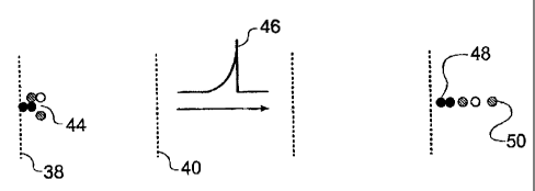
Figure 3 illustrates the principle of the exponential box I4 schematically. A
packet of ions 44 enters the exponential box at the first mass filter
electrode 38, which
has a zero applied voltage. The ions then travel to the exponential pulse
electrode 40
to which the time varying voltage profle 46 (in this case having the form l t
= ho exp
I S (t/ ) which, as previously mentioned, is negative going since the ions are
positive) is
applied by the drive circuit 41. After passing. the exponential pulse
electrode, the ions
are spatially separated, with the heaviest ion 48 (largest m/z ratio) at the
rear and the
lightest ion 50 (lowest m/z ratio) at the front.
Figure 4 illustrates a further embodiment of the invention which employs a
different type of ion detector 16 from that of embodiment shown in Figure 2.
The
construction of the ion source 12 and exponential box I4 shown in Figure 4 are
the
same as those shown in Figure 2, and the same reference numerals are used for
equivalent parts in Figures 2 and 4.
With regard to the ion detector 16 of Figure 4, downstream of the exponential
pulse electrode 40, a first detector electrode 60 is located, which is annular
with an
aperture for the passage of ions. This electrode 60 acts as an energy
selector.
Following this, a second detector electrode 62 is located in the ion path.
This is in
effect a single element detector, and may be, for example, a Faraday cup. A
voltage
supply 63 is provided for applying voltages to the first detector electrode 60
and the
second detector electrode 62.
CA 02450465 2003-12-11
WO 02/103746 PCT/GB02/02565
-16-
In use, the first detector electrode 60 and the second detector electrode 62
are
set to a potential of Vt+V,. volts, where Vt is the time varying voltage
profile as defined
above, and Vr is a bias voltage selected to repel, or reflect, ions having
energies less
than Vr electron volts. Hence, only ions having energies equal to or greater
than Vr
electron volts pass through the first detector electrode 60 and reach the
second
detector electrode for detection. An alternative arrangement omits the first
detector
electrode, so that ions are repelled at the second detector electrode
immediately before
non-repelled ions are detected.
To obtain a set of mass spectrum data, V,. is initially set to zero, so that
all the
ions in a packet are detected. For the next packet, Vr is increased slightly
to reflect the
lowest energy ions, and allow the remainder to be detected. This process is
repeated,
with Vr increased incrementally for each packet, until the field is such that
all ions are
reflected and none are detected. The data set of detected signals for each
packet can
then be manipulated to yield a plot of ion current against m/z ratios, i.e.
the mass
spectrum.
Alternatively, the ion detection can be carried out by starting with a high
value
of Vr with repels all the ions. Vr is then reduced for each successive ion
packet until Vr
is zero and all ions in a packet are detected. Indeed, as long as V,. is swept
over a
number of different values corresponding to the full range of ion energies,
the
detection procedure can be carried out in any arbitrary sequence. All that is
required is
that the complete range of ion energies of interest is covered during the
detection
procedure. The resolution of this ion detector can be altered as required by
changing
the number of measurements with different values of Vr which are made. A
larger
number of measurements over a given ion energy range gives better resolution.
Also,
it is also possible to set the ion detector to particular voltages, or narrow
voltage
ranges, in order to concentrate on one or more narrow m/z regions.
Table 1 presents some sample detection data for a range of m/z ratios. This is
obtained for an exponential voltage pulse having a time constant of 0.77 bus,
exponential box length d = 3 cm and Vo = -1 V. The table values are calculated
using
CA 02450465 2003-12-11
WO 02/103746 PCT/GB02/02565
-17-
equation (9) of the appendix below with the two constants of integration taken
to be
zero.)
m/z Crossing Velocity Kinetic EnergyMaximum
(T~) Time (ms-1 ) (eV) Exponential
(N~s) Voltage
volts
1 2.12 3.90 x10⁴ 7.87 15.733
2 2.16 3.90 x10⁴ 15.73 31.465
3.90 3.90 x10⁴ 78.66 157.33
30 .74 3.90 x10⁴ 236.0 71.98
60 5.28 3.90 x10⁴ 72.0 943.96
120 5.81 3.90 x10⁴ 943.9 1887.9
S Table 1
The data of Table 1 also illustrates how the ions are spatially separated when
they leave the exponential box. Values for m/z ratios of up to 120 are given.
However,
this is for illustration only and it should be appreciated that the invention
can also be
10 applied to higher m/z ratios. Despite having the same velocities, the ions
with the
lowest m/z ratios have the shortest crossing times (this being the time taken
to travel
the distance c~, indicating that they left the exponential box first. This
attribute of
spatial separation implies that it is also possible to operate a mass
spectrometer
according to the present invention in a simple non-energy selective mode, in
which
1 S the spatial separation is used to distinguish between ion species.
There are a number of ways in which the time varying voltage profile can be
generated by the drive circuit 41.
Figure S shows an analogue exponential pulse, as a graph of voltage against
time. Such a pulse may typically be generated by means of a drive circuit 41
comprising a low voltage analogue circuit and a step-up transformer which is
necessary to achieve the high voltages required.
Figure 6 shows a digitally synthesised exponential pulse, having the step
features characteristic of digital signals. This step size needs to be small
enough to
CA 02450465 2003-12-11
WO 02/103746 PCT/GB02/02565
-18-
prevent the ions from "feeling" the individual steps, as this affects the
acceleration of
the ions, but the intrinsic capacitance of the exponential box will in any
case tend to
smooth the steps somewhat. A pulse of this type can be generated digitally,
for
example under hardware or software control, e.g. using a personal computer.
For
example, the drive circuit 41 can comprise a number of low voltage digital
waveform
generators connected together in parallel to achieve the necessary high
voltages.
Figure 7 shows a frequency modulated pulse train of pulses of constant
amplitude, short duration, and increasing repetition frequency. The repetition
frequency increases exponentially. A series or sequence of pulses of this type
gives an
effect entirely equivalent to an exponential pulse, because the time average
of the
pulses corresponds to an exponential pulse. Alternatively, the pulse sequence
can have
a constant repetition frequency and exponentially increasing pulse amplitude,
which
also has an exponential time average. However, a pulse sequence of this type
can be
more complex to produce than one having constant pulse amplitude. Preferably
the
pulses are square wave pulses, although, as is well-known, it is not possible
to
generate perfect square wave pulses, especially of high amplitude and short
generation. This will have a detrimental effect on the resolution achievable,
but on the
other hand, use of a~ pulse train may be advantageous in circumstances where
the
electronics required for frequency modulation are more readily achievable than
those
for generating exponential pulses.
Figure 8 shows a circuit diagram of a drive circuit suitable for the
generation
of analogue exponential pulses such as the pulse shown in Figure 5.
The generation of exponential pulses by the drive circuit is based on the
forward biased characteristic of a p~ junction, which can be written as I =
lo(exp(qVlkT)-1), where I is the current through the junction, Io is the
junction reverse
biased current, q is the charge on an electron (1.6x10⁻¹⁹ Coulombs), k is the
Boltzmann constant, T is absolute temperature and V is the voltage across the
junction. As long as exp(qTllkT)»l, the current is truly exponential with
voltage.
Therefore, an exponential voltage pulse can be produced by converting the
junction
current to a voltage. The requirement that exp(q1llkT)»1 sets a lower limit to
the
CA 02450465 2003-12-11
WO 02/103746 PCT/GB02/02565
-19-
voltage across the junction. The upper limit to this voltage is set by the
Ohmic voltage
drop across any resistance connected in series with the junction, which occurs
at high
values of the current.
The Ohmic resistance and the reverse current are dependent on the fabrication
and design of the pn junction. The emitter-base junction of a transistor is a
suitable
junction, as is a diode junction. However, a transistor is to be preferred, as
its
characteristics with regard to the Ohmic resistance and reverse current are
superior.
If the voltage applied to the junction is increased linearly with time (t) to
give
a voltage ramp of the form I~ = at, then the current will be of the form I =
exp(t/z)
where 1/z corresponds to qalkT. Conversion of this current to a proportional
voltage
gives an exponential voltage of the form required for operation of the mass
spectrometer, namely h= yoexp(t/z).
The circuit diagram of Figure 8 shows a drive circuit 41 having components
which can be used to achieve this. The drive circuit 41 is based on a
transistor 70 with
its base and collector connected together, so that the emitter-base junction
of the
transistor forms the pv~ junction of the drive circuit 41. The transistor 70
is selected for
the characteristics required to give the desired voltage range, and all the
devices in the
circuit 41 have a high enough upper frequency limit to follow the exponential
voltage
change with time.
The circuit 41 uses a timer chip 72 (such as a 555 timer) to develop the
linearly increasing voltage ramp which is applied to the transistor 70. The
timer chip
has eight pins, indicated in Figure 8 as P1 to P8, with the voltage ramp being
obtained
at pin P6. The value of the voltage ramp increases from 1/3 of the voltage of
voltage
supply 73 to 2/3 of this voltage. In this case, voltage supply 73 is 15V, so
the voltage
ramp changes from 5 V to 10 V.
The value of the voltage proportionality constant a (and hence the slope of
the
voltage ramp) is determined by the level of charging current entering
capacitor 74.
This is in turn determined by the value of resistor 76. A voltage divider 78
is provided
to reduce the range of the voltage ramp produced by the timer chip 72 to a
range
suitable for the p~ junction formed by the transistor 70. A first operational
amplifier
CA 02450465 2003-12-11
WO 02/103746 PCT/GB02/02565
-20-
80 located between the voltage divider 78 and the transistor 70 acts as an
impedance
matching voltage follower. This amplifier 80 needs to have a sufficiently high
slew
rate to follow the exponential voltage.
A second operational amplifier 82 converts the junction current to the desired
exponential voltage. Finally, a step-up transformer 84 increases the
exponential
voltage to a level required for operation of the mass spectrometer.
Figure 8 shows various values for components used in the drive circuit 41. It
is
to be understood that these values are for the purposes of example only, and
that an
analogue circuit performing the required function could be constructed from
components having other values. Furthermore, it is to be noted that the drive
circuit of
Figure 8 is designed for use in a constant temperature environment.
Everything described hereinabove concerns positive ion mass spectrometers.
Negative ion mass spectrometry is less commonly employed but the principles of
the
present invention can equally well be applied to negative ions. In such a
case, the
polarities of the electric fields described herein would need to be reversed,
including
use of a positive going exponential pulse.
A further embodiment uses a positive going exponential pulse to provide a
mass filter for positive ions. The pulse is applied to the first electrode of
the
exponential box (the first mass filter electrode 38 in Figures 2 and 4). This
is in
contrast with the embodiments already described, in which the exponential
pulse is
applied to second electrode of the exponential box (the exponential pulse
electrode 40
in Figures 2 and 4) and the frst electrode is grounded. However, the grounding
of the
first electrode in these embodiments serves to prevent the build-up of space
charge
arising from the ions deflected by the second ion repeller electrode 36.
Therefore, if a
positive going pulse is applied to the first electrode of the exponential box
to filter
positive ions, an additional electrode which is grounded should be provided
upstream
of the exponential box to collect deflected ions.
Additionally, negative ions could be filtered by applying a negative going
pulse to the first electrode of the exponential box.
CA 02450465 2003-12-11
WO 02/103746 PCT/GB02/02565
-21-
REFERENCES
[1] WO 83/00258
[2] "Enhancement of ion transmission at low collision energies via
modifications to
the interface region of a 4-sector 'tandem mass-spectrometer", Yu W., Martin
S.A., Jouf°~al of the American Society for Mass Spectronomy, 5(5) 460-
469 May
1994
[3] "Advances in multidetector arrays for mass-spectroscopy - A LINK (DIMS)
Project to develop a new high-specification array", Birkinshaw K.,
Transactions
of the Institute of Measurernerzt and Control,16(3), 149-162, 1994
[4] "Focal plane charge detector for use in mass spectroscopy", Birkinshaw K.,
Analyst, 117(7), 1099-1104, 1992
CA 02450465 2003-12-11
WO 02/103746 PCT/GB02/02565
-22-
APPENDIX
MATHEMATICAL TREATMENT OF THE PRINCIPLE OF OPERATION OF THE
EXPONENTIAL BOX
Assumptions:
(i) The ion packet is positioned exactly at the entrance of the exponential
box at the start of the exponential voltage pulse,
(ii) the ion packet width is negligible with respect to the length of the
exponential box so that all ions have the same path length within the
box, and
(iii) all ions have axial velocity components of zero at the start of the
exponential pulse.
The foregoing simplifications do not have to be made and the effect of taking
these
factors into account is, in general terms, to degrade the resolution of the
exponential
box filter. This simplified theory explains the underlying principles of
operation,
however.
For an ion of mass na and velocity v the ion kinetic energy, E;on, is given
by:
Eon = mv' (1)
2
As can be seen, if all ions are given the same velocity in the exponential box
then the ion mass is simply proportional to the ion energy. Measuring the ion
energy
CA 02450465 2003-12-11
WO 02/103746 PCT/GB02/02565
-23-
is intrinsically simpler than the velocity selection method commonly used in
mass
spectrometers (where all ions have the same kinetic energy).
If an ion has a (positive) charge of q and it is placed in an electric field
E,
between two electrodes, then it will experience an instantaneous force, equal
to the
product Eq, that will cause it to accelerate towards the negative electrode.
From
Newton's second Iaw of motion the ion will be accelerated at a rate that is
inversely
proportional to the ion mass:
d 2s - Eq (2)
dt2 m
where s is distance travelled towards the negative electrode and t is the time
for which
the field was applied.
If a voltage Ir is applied across two electrodes that are spaced d apart, then
the
resulting field E is given by:
E = V/d (3)
In the case of the exponential box, the voltage is time dependent and the
instantaneous voltage Vr is increasing exponentially with time:
_t
Vr = Vo expC z ~ (4)
where ho is the voltage at t = 0 and z is the exponential time constant.
Combining equations (2), (3) and (4) gives:
CA 02450465 2003-12-11
WO 02/103746 PCT/GB02/02565
-24-
d Zs q~° exp t (5)
dt2 dm Cz
The instantaneous velocity vt can be obtained by integration of equation (5)
with respect to t:
v~ = f d 2s dt = J~~° exp t dt (6)
° dt2 dm ~z~
0
or
vl = ~~m° expC i ~ + C (7)
The distance travelled by the ion, st, after time t is obtained by integrating
equation (7):
st = fv~dt= z2q~° exp t +Ct+C' (8)
° d»a
Assuming the constants of integration Ct and C to be zero equation (~)
simplifies to:
s1 = ~2q~° exp t (9)
dfra C z
If the exponential pulse time, t, and inter-electrode gap, d, are arranged so
that
s~ = d, then, after rearrangement, equation (9) becomes:
CA 02450465 2003-12-11
WO 02/103746 PCT/GB02/02565
-25-
z
Yo expC t ~ ~ rnd (10)
z z' q
Now, substituting for Iloexp(t/i) from equation (10) into equation (7), and
noting that the constant of integration is zero in this simplified treatment,
vt is found
to be independent of the ion mass:
yr = d (11)
z
Hence it has been shown that, when the ion exits the exponential box, its
velocity is only dependent on the length of the exponential box, d, and the
exponential
pulse time constant, i. In other words, all ions will have the same velocity
irrespective of their masses.