Note: Descriptions are shown in the official language in which they were submitted.
CA 02450923 2003-12-23
-1
~L'rI_~LE GATING 1~LOZZLE
Field of The Inventloa
The t invention relates to a method and apparatus for runnerless injection
molding, provided with a novel valve gate for permitting at least two gates to
be
controlled in a single nozrle. .In particular, the invention relates to an
improved method
and apparad~s for molding hollow articles and prefomas for blow molding which
have a
layered wall .
Bsd~round of the Invention
This invention concerns injection molding nozzles used to iqjoct plastic
material
into the cavity of a mold. Such noales receive molten plastic maurial from an
injection
molding machine and diroct the same into a mold cavity through a passage
called a gate.
Two methods exist for this transfer: thermal, or open, gating; and valve
gating.
In thermal gating, the gate is an open aperture through which plastic can pass
doting injection of plastic material. The gatt is rapidly cooled at the end of
the injection
cycle to '" the plastic material which remains in the gate to act as a plug to
prevent
drool of plastic material into the mold cavity when the mold is open for
ejection of parts.
In the next injection cycle, tln; cooling to tlar gate is rarwved and hot
plastic material
pushes the plug into the mold cavity, where it melts and mixes with the new
melt stream.
In valve gating, gate opening and closing is independent of injection pressure
and/or cooling, and is achieved mechanically, with a pin that travels back and
forth, to
open and close die gate.
Generally, valve gating is preferable to thermal gating because the gate mark
left
by valve gating on the finished molded part after injection is complete is
much smaller
CA 02450923 2003-12-23
-2-
than that which results from thermal gating. Larger gate sizes can also be
used in valve
gate systems, leading to fasts filling of the mold cavities and therefore
shorter molding
cycle times.
However, some disadvantages are frequently associated with valve gates. These
disadvantages include "weld lines", which are areas where multiple melt flow
fronts
meet, and valve stem wear. Weld lines tend to introduce was or Ions of
mechanical
strength into the finished part and result from tln; fact that the valve stem
is surrounded
by the plastic material, splitting the melt st-oam, which is later rejoined at
the end of the
stem, and this re-combining of the stream leads to weld lines. Hence, there
exists a need
for a gate design which allows for the melt stream, or streams in the case of
two or more
plastic materials, to remain separate while still being contmUod with a common
valve
stem.
The valve stem is also subject to wear from mechanical stress, due to stem
deflection from the incoming pressurized melt, and thermal stress, from
constant contact
with the melt. This wear is exacerbated in cases where reinforced plastic
materials, i.e.,
those containing glass or other fibers or materials, are injected. H~ce, there
exists a need
for a gate design which mitigates the wear of the valve stem.
The injection of two or more separate melt streams into a mold cavity, whether
simultaneously or sequentially, is referred to as co-injection, and leads to
layered wail
structures in hollow articles and blow molding preforms. The prior art
includes a
multitude of processes and apparatuses for forming molded articles from
multiple plastic
materials by co-injection. For e~cample, U.S. Pat. Nos. 5,028,226 and
4,717,324 show
simultaneous and sequential co-injection apparatuses and methods,
respectively. Both
patents show one nozzle dedicated to each mold cavity wherein the cavity is
filled by
injecting two or more resins through a single gate.
CA 02450923 2003-12-23
-3-
In the systems shown in each patent, a valve stem is used to pnwent resin flow
through the gate after injection is complete. In these systems, the hot runner
systems
employed to receive the various resins from their source for conveyance to the
mold
cavities are very complicated:. Consequently, such hot runner systems lead to
mold
designs which are not compact and thereby allow fewer cavities and fewer
articles to be
molded within a given space on a molding machine.
U.K. Patent No. 1,369,744 discloses a sequential co-injection system using
separate channels, commonly referred to as spree channels, for each melt
stzeam, and
sliding shuttles which fiu~ction as valve stems to open and close the
connection between
the injection machine and the channels. However, these separate melt channels
converge
into a single common gate area prior to injection, so that some potential for
contamination betv~roen streams exists. Furtlamnore, the shuttles are
hydraulically
actuated, increasing the complexity of the nozzle and allowing the risk of
leaking
hydraulic fluid to contaminate the streams.
U.S. Patent No. 4,470,936 also discloses a sequential co-injection system
using
separate spree channels for each melt shram, with each spree channel being
independently heated and converging to a common gate. In this system, a
shuttle ball or
swing gate switches the flow of material from one spree channel to the other.
This system
also sui~ers from the potential for contamination between streams, such as
described
above for U.K. Patent 1,369,744. This is a sp~ial concern as wear of the
shuttle ball or
swing gate is likely in normal use.
ZS
U.S. Patent No. 5,651,99$, assigned to the assignee of the present invention,
discloses a method and apparatus for either sequential or simultaneous co-
injection
utilizing two opposing injection nozzles on the core and cavity sides
respectively of the
CA 02450923 2003-12-23
-4-
mold. Although effective, this arrangement requires an additional injection
nozzle which
must also receive resin from an injection unit on the opposite (movable) mold
core half.
This arrangement significantly increases the space requirements for the mold
and may not
be acceptable in some applications.
U.S. Patent No. 5,125,816 is similar to U.S. Patent No. 5,651,998 in that
sequential co-injection is achieved by opposing gates on both the mold core
and cavity
respectively. However, in this arrangement the moveable mold half is fitted
with slide
cores containing tubular passages for feeding resin to one half of the molded
part. These
slide. cores move via hydraulic cylinders to define secondary mold cavities,
which arc in
turn filled by gates on the opposing mold half. This system suffers from
disadvantages
due to its complexity, the additional mold hardware requirements, including
the
aforementioned slide cores and additional injection nozzles; and the need for
special
manufacturing attention due to tight tolerances.
U.S. Patent No. 3,873,656 shows a co-injection apparatus wherein at least two
plastics are injected into a mold cavity through different gates, using a
valve gating
system. This design is only suitable for molding very large plastic articles.
Also, the hot
runner system taught does not have the capability for allowing separate
temperature
control of the different resin types, which inherently limits the variety of
resins that can
be used together in one system. Furthermore, since the gates are far apart
from one
another, the flow of each resin will not be synunetrical throughout the part,
but instead
will be biased in the area of the gate.
U. S. Patent No. 4,289,191 shows injection molding of molten wax into a
precision metal die, wherein hollow parts are molded to extremely tight
tolerances of
10.012 mm. The wax stream flows from a nozzle having a central bore to a
cavity or
space formed between the nozzle tip, which has a relief channel, and the
socket on the
CA 02450923 2003-12-23
-S-
exterior of the die, and then into two or more separate spore ports that feed
into the mold
cavity. Control of wax flow is accomplished by a retractable plunger in the
nozzle which
functions like a conventional valve stern. Although more than one spree port
is employed
to supply material to the mold, tlurse- ports are downstream the valve in the
nozzle. Also,
the valve stem obstructs the melt flow by being in the center of the melt
stream, leading
to weld lines. Finally, no provision is made for two or more separate resins
to be injected
through the two or more spree ports, so this method cannot be used for co-
injection
Pm'Po~s.
U.S. Patent No. 5,645,874 shows a multiple gate nozzle in which each nozzle
associated with a respective gate is equipped with an individual heater to
allow
independent thermal gating. In this arrangement, a central flow passage feels
a plurality
of radially extending branch passages leading to each respective gate, and as
such, cannot
accommodate multiple sources of resin or even sequential melt flow, and
therefore cannot
be used for co-injection purposes.
U.S. Patent No. 4,702,686 shows a nozzle vvhercin a tapered plate divides a
central flow channel into two partial channels prior to the nozzle tip and
gate. This
nozzle cannot accommodate the separate, different, resin sources require for
coinjection
purposes.
Summary of The Invention
It is an object of the present invention to provide an novel apparatus and
method
for injecting at least two plastic materials into a mold cavity which obviates
or mitigates
at least one of the disadvantages of the prior art.
According to a first aspect of the present invention, tta~re is provided a
method of
co-injecting at least two different plastic materials to form a mufti-layer
molded product
CA 02450923 2003-12-23
-b
using a hot runner injection molding machine with a separate channel for each
material,
each channel having an end in communication with a separate gate for feeding
an
injection mold, the method comprising:
(f) heating the plastic materials in their separate channels or storage areas;
(ii) injecting a selected amount of a first plastic material from a first
channel
through a first gate into the injection mold and preventing further flow of
material from
the first channel;
(iii) injecting a selected amount of a second plastic material from a second
channel through a second gate into the injection mold, said second gate being
separated
from said first gate by a gate separating means;
(iv) injecting a selected amount of a third material, said third material
being
selectod from one of said first plastic material and any other plastic
material, said third
material being injectod from its respective channel via its respective gate,
said respective
gate being separated from said second gate by a gate separating means; and
(v) moving a valve stem forward to close each said gate.
According to another aspect of the present invention, there is provided a
method
of co-injecting at least two different plastic materials to form an article
having abutting
portions of said different plastic materials using a hot runner injection
molding machine
with a separate channel for each different plastic material, each channel
having an end in
communication with a respective separate gate for feeding an injection mold,
comprising
the steps of
(f) heating each different plastic material in its respective separate
channel;
(ii) injecting a metered amount of a first plastic material from a first
channel
through a first gate into the injection mold and simultaneously injecting a
metered
amount of a second plastic material from a second channel through a second
gate into the
injection mold, said second gate being separated from said first gate by a
gate separating
means;
CA 02450923 2003-12-23
-'-
(iii) injecting a metered amount of a plastic material into the injection mold
from its respective individual channel through its respective gate; and
(iv) moving a valve stem to block all gates leading into the injection mold.
According to another aspect of the present invention, there is provided a
method
of co-injecting at least two different plastic materials to form a mufti-layer
molded
product employing a hot runner injection molding machine with a ssparate
channel for
each material, each channel having an exit in communication with a eve
separate
gate for feeding an injection mold, the method comprising the steps of
(f) heating the plastic materials in their separate channels;
(ii) injecting a selected amount of a first plastic material from a first
channel
through a first gatc into the injection mold and inhibiting further flow of
material from
said;
(iii) injecting a selected auiount of a second material from a second channel
through a second gate into the injection mold, said second gate being
separated from said
first gate by a gate separating means comprising a protrusion that engages a
valve stem to
support said valve stem;
(iv) injecting a selected amount of a third material, said third matexial
comprising
at least one of said first material and another material, said third material
being injected
from its respective channel and its respective gate into said injection mold;
and
(v) moving said valve stem to close at least one of said gates, each gate
which is
not closed by said valve stem being gated by thermal shut-off to inhibit the
flow of plastic
into the mold.
According to yet another aspect of the present invention, there is provided a
hot
runner injection molding apparatus for co-injecting at least two plastic
materials into a
forming mold, comprising:
a separate channel for each of said at least two plastic materials;
CA 02450923 2003-12-23
-g-
a separate heating means for each of said separate channels;
a separate gate for each of said at least two plastic materials, each said
gate
being in communication with a corresponding one of said separate channels;
a valve stem movable between a first position wherein each said separate gate
is open and a second position wherein each said separate gate is closed; and
a gate separating means comprising a protrusion separating each said separate
gate from each other said separate gate, said protrusion co-operating with
said valve stem
to inhibit deflection thereof.
According to yet another aspect of the prat invention, there is providod a hot
runner injection molding apparahis for co-injecting at least two different
plastic materials
through separate channels to farm a mufti-layer moldod product, each separate
channel
being independently heated and having an end in communication with a
respective
separate gate entrance into a forming mold, a gate separating means to prevent
intermixing of the different plastic materials prior to exit at the gates, and
a valve stem
capable of longitudinal movement to permit and inhibit the flow of the
different plastic
materials through said gates, said gate separating means engaging a portion of
said valve
stem to inhibit lateral deflection thereof.
The present invention provides a nozzle for plastic injection molding machines
whereby flow disturbances and the resulting weld lines, which normally occur
with
known valve gate systems, are reduced. Further, the present invention provides
an
injection system and method that employs relatively simple nozzle and hot
runner
designs. The present invention also provides a space-efficient, mufti-material
injection
2S system for efficiently molding a plurality of articles in a mufti-cavity
mold. The present
invention also provides an injection system and method wherein gates of
different sizes
can be accommodated in a single injection nozzle, each gate size being self
according
to the viscosity of the particular plastic material flowing through it.
CA 02450923 2003-12-23
_g_
The present invention provides a novel method for runnerless injection
molding,
provided with a valve gate assembly, including at least two melt stmams
separated at the
edge of the mold cavity by a gate separating means, a valve stem that is
reciprocally
movable and at least two gates that are opened and closed by the valve stem.
Brief Description of T6e Dnwiog~
The p~tsent invention will now be describe, by way of example only, with
reference to the attached Figures, wl~in:
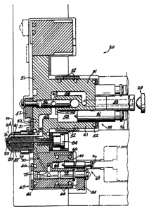
Figure 1 is a sectional view of a hot n~nneer-nozzle assembly for a mold
cavity
wherein two separate plastic materials fed to the nozzle tip and controlled by
a single
valve stem;
Figure 2 is an expanded view of the nozzle assembly of Figure 1;
Figure 3 is a set of sectional views of a molded article detailing the layesod
wall
structure after first, second, and third shots of plastic material;
Figure 4a is an end view of a nozzle assembly with three gates in accordance
with
the present invention;
Figure 4b is a section of the nozzle assembly of Figure 4a, taken along line A-
A
of Figure 4a;
Figure 4c is a section of the nozzle assembly of Figure 4a, taken along line B-
B of
Figure 4a;
Figure Sa is a side view of a valve stem for the nozzle assembly of Figure 4a;
and
Figure Sb is an end view of the valve stem of Figure Sa.
Description Of the Preferred Embodiments
In Figure 1 an embodiment of a valve gate assembly and injection nozzle in
accordance with the present invention is indicated generally at 20 which is,
in this
embodiment of the present invention, a co-injection hot nuuxt system which
accommodates two plastic materials. One plastic material is provided from a
source
CA 02450923 2003-12-23
-10-
comprising extruder 24 and the other plastic material is provic~d from a
separate extr~a~
(not shown). As used herein, different plastic materials is not intended to be
limited to
different material compositions, such as PET versus EVOH, but can also
comprise,
without limitation, materials with generally the same composition but
different
characteristics, such as PET in different colours or virgin PET versus
recycled PET,
foamed plastic materials versus non-foamed plastics, etc.
In this example, the portion of the hot nmner system connected to extruder 24
is
maintained at a temperatiure rrangir ; from 500° to 550°F, the
optimum processing
temperatim for a thermoplastic resin such as polyethylene teraphth,alate, or
PET, by
suitable heaters in weU-known fashioa. Conversely, the portion of the system,
illustrated
in broken lines, which is connected to the second extn~der is maintained at a
different
temperature, such as the range from 400° to 440°F, the optimum
processing tearperature
for a thermoplastic resin such as EVOH. It is to be noted that the plastic
materials
selected and their optimum processing temperatures are merely examples of the
present
invention and their use in the present description is not intended as a
limitation of the
present invention.
A c~tral manifold block 51 maintaira~d at an operating temperature ranging
from
500 to 550°F by heating elements 52 and receives plasticized resin from
extender 24
through channels 53 and 54. A spool, or rotary, valve 56 is in circuit with
channel 54 and
operated by link mechanism 57, and controls the charging of reservoir 58 of
the shooting
pot, or injection cylinder, 59 equipped with an injection piston or charging
piston 61.
Valve 56 is formed with a transverse throughbore 62 and is shown in the close
position
in Figure 1.
With reference now to Figures 1 and 2, reservoir 58 communicates with a nozzle
assembly 64 via channel 63. Htating elements 52 maintain the desired
processing
CA 02450923 2003-12-23
-11-
temperature of channel 63 as the PET or other plastic material progresses
through to
channel 90 of nozzle assembly 64 to a gate 76a. As shown, gate 76a is
separated from an
adjacent gate 76b by a gate separating means. In a preferred aspect of the
present
invention, the gate separating means is in the form of a protrusion 86 that
partially
overlaps. central valve stem 83, which is shown in the retracted position in
these Figures.
This partial overlap of valve stem 83 and protrusion inhibits any lateral
aligannent
problams that might ordinarily occur where the stem moves longitudinally
backwards and
forwards over millions of injection cycles under very high injection pressures
exceeding
twenty thousand psi. While the overlap between protrusion 86 and steer 83 is
preferred,
it is not essential to the invention and, as wilt be understood by thox of
skill in the art,
the gate separating means neod not be a protrusion and can instead be any
.suitable barrier
between the gates 76.
1S As best seen in Figure 1, a manifold segment 65 is secured to manifold
block 51
and is heated by elements 66 to maintain optimum temperature (400° to
440°F) in the hot
runner connecting the second extruder (not shown) to channel 67 and to a
reservoir 68 of
a second shooting pot 69 which is equippod with an injection err charging
piston 71. Here
again, a spool or rotary valve 72 (shown in the closed position relative to
channel 67 in
Figure 1 ) controls charging of reservoir 68. In the closed position of the
spool valve 72,
reservoir 68 communicates with nozzle assembly 64 via a channel 70 through a
cut-out
?5. When the spool valve 72 is open, channel 70 is closed and a link mechanism
85
operates to rotate valve 72.
ZS As shown in Figure 2, nozzle assembly 64 includes a central spigot 73 in
thermal
contact with manifold block 51 immediately adjacent local beating elements 52.
and
spigot 73 is preferably fabricated from a good nxtallic thermal conductor such
as
beryllium copper. Spigot 73 is supported by minimal bearing surfaxs ?7,78,
best seen in
CA 02450923 2003-12-23
~ 12-
Figure 2, in a housing 79 and is spacod, from spigot 73 along substantially
its entire length
to form an insulating air gap 8I. Air gap 81 inhibits conduction of heat from
the spigot
73 to the housing 79 to maintain the desirod process temperature, controlled
by heating
means 82, as the plastic material, such as EVOH, progresses through channel 80
of
housing 79 to gate 76b.
The size of each of gates 7Ga and 7bb can be selected as desired, largely
independent of the other of gates 76a and 76b, which is advantageous in
situations where
the viscosities of the different resin streams are significantly different or
wherein a
significantly larger amount of one material than the otls~ is to be injected
in an injection
cycle.
Thus, it is apparent that the nozzle and valve gate and the hot rcan~ system
of the
present invention is effective to maintain different optimum process
temperatures
appropriate to two diffcrcnt plastic materials from the source of the plastic
materials to
the nozzle gates.
As will be apparent to those of skill in the art, because the plastic material
is
supplied to gates 76a and 7fib via channels 80 and 90, respectively, the
plastic. materials
do not contact the majority of stem 83 and thus wear of stem 83 is reduced in
comparison
to conventional designs.
A preferred method of operation will now be described with reference to the
PET
and EVOH example described above. To prime the hot runner system initially,
extruder
24 and the second extruder, including their respective co-operating shooting
pots 59 and
69 are purged and the extruders are moved into operative position relative to
their
respective manifolds. With valve stem 83 and spool , valves 56 and 72 in the
open
position, shooting pot reservoirs 58 and 68 are charged with PET and EYOH
material,
CA 02450923 2003-12-23
-13
respectively. Next, valve stem 83 is closed by a piston 84 and purged resin in
the mold
cavity is removed.
Thcreafler the mold is closed and clamped, valve stem 83 is opened and the
following sequence is perform. First, spool valve 56 is closed and injection
piston 61
is advanced until it bottoms at the point indicated by the reference numeral
100,
discharging a measured amount of PET into the mold cavity through channel 63
and gate
76a, which is separated from the adjacent gate 76b by a protrusion $G. This
constitutes
the first shot of PET into the mold cavity, as shown schematically at F in
Figure 3.
I0 . .
Piston 61 is held forward (in i~ bottomed position 100) blocking to
reservoir 58 to prevent backflow of PET compound from channel 63 into
reservoir 58.
That is, the piston 61 is held bottomed to block access to reservoir S8
because upon
subsequent operation of piston 7I to inject EVOH, the EVOH injection pressure
would
have a tendency to displace PET from channel 63 back into reservoir 58.
Next, spool valve 72 is closed to the second extruder and opened to channel
70.
Injection piston 71 is moved until it bottoms at IOI and thus discharges a
measured
amount of EVOH into the cavity through channel 70 and gate 76b. This
constitutes the
first shot of EVOH into the mold cavity (second shot of resin) to develop the
three-layer
wall as shown schematically at S in Figure 3. As will be apparent, flee volume
of the first
and second shots of resin is less than the total volume of the mold cavity.
Next channel 70 is closed by appropriate rotation of spool valve 72 and spool
valve 56 is opened, allowing extruder 24 to complete the filling of the mold
cavity with
PET and to pack the molded part while piston 61 remains bottomed, blocking
access to
reservoir 58. This step constitutes the second shot of PET (third shot of
resin) to develop
CA 02450923 2003-12-23
-14-
a five-layer wall, as shown schematically at T in Figure 3. Thus, a five-layer
wall
structure is molded using two resins.
After packing is completed, valve stem 83 is moved forward to the closed
position, where it blocks both gates 76a and 76b and piston 61 is now freed to
move.
Extruder 24 is operated to recharge reservoir 58 of shooting pot 59,
displacing piston 61
until it contacts an injection stop Sa, shown in Figure 1. The positioning of
stop Sa
controls and measures the amount of PET introduced i~o the reservoir 58.
In similar fashion, the injection stop Sb controls and measures the amount of
EVOH introduced into the reservoir 68. During the course of packing the mold
cavity,
the reservoir 68 is recharged by opening spool valve 72 to allow the second
cxt:vder to
displace piston 71 until the piston contacts its injection stop Sb, thus
charging reservoir
68 with a measured amount of EVOH compound. After a suitable cooling interval,
the
I S mold is opened and the article is ejby known means. The above cycle is can
then
be repeated, in continuous, automatic fashion, to generate additional layered
articles.
It is also contemplated that articles comprising two or morn layers of
materials
can be manufactured with the present invention, wherein one of the layers
comprises a
foamed material. For example, a first plastic material, such as a co-polymer
of ethylene
and vinyl acetate, can be injected into the mold to form the outer layer of
the final article
and a second plastic material, such as polyproylene, is then injected to fornn
a foamed
core. Another layer of the first plastic material can then be injected to seal
the foam
material between the layers of the first material, much like a sandwich. It is
also
contemplated that the simultaneous injection of two or more different
materials can also
be performed with the present invention. This allows, for example, the
manufacture of
articles of PET-PEN resin blends.
CA 02450923 2003-12-23
-IS-
As will be apparent to those of skill in the art, the present invention need
not be
limited to nozzle and valve gate assemblies with only two gates and can
instead include
three or more gates, if desired. In another embodiment of the present
invention, shown in
Figures 4a, 4b and 4c, a nozzle assembly is shown wherein three ~parate gates
food tht~ee
different plastic materials into one mold cavity. In this embodiment, the
gates 200, 204
and 208, shown in Figure 4a, can be different sizes or the same size (not
shown) and each
gate is separated from the other two by a protrusion 212, best seen in Figures
4b and 4c.
Figure 4a shows the pie-shaped arrangement of the three nozzle portions 216,
220
and 224 with insulating plates 228a, 228b and 228c, made of a suitable
material as will
occur to those of skill in the art. Plates 228 separate each nozzle portion
216, 200 ail
224 to maintain different thermal profiles for each plastic material type
being carried to
each gate 200, 204 and 208, as dictated by the properties of particular
materials.
Figures Sa and Sb show a valve stem 240 for the nozzle assembly of Figures 4a,
4b and 4c and the slot 244 which engages protrusion 212, slot 244 being
defined between
pins 248, 252 and 256 which close respective ones of gates 200, 204 and 208
when stem
240 is advanced toward protrusion 212. While the discussion above has only
described a
single stem in the nozzle assembly, it is contemplated that in some
circumstances more
than one valve stem can be employed in the assembly, each valve stem being
individually
actuated and gating one or more gates.
It is contemplated that in some circumstances both valve gating and thermal
can
gating can be employed in a single nozzle assembly in accord~e with the
present
invention. For example, as illustrated in Figure 4a wherein gate 204 is much
smaller than
gates 200 and 208, one or more gates can be much smaller, relative to the
other gates, in
the nozzle assembly and these smaller gates can be thermal gated in a
conventional
manner while larger gates, such as gates 200 and 208, can be valve gated.
CA 02450923 2003-12-23
-16-
It will be understood, of course, that modifications can be made to the
embodimcnts of the invention illustrated and described herein without
departing from the
scope and purview of the invention as defined by the aclaims.