Note: Descriptions are shown in the official language in which they were submitted.
CA 02451362 2004-10-O1
METHOD AND APPARATUS FOR CLAMPING A KNIFE
Background of the Invention
The present invention related to a method and apparatus for clamping a knife
in
a wood chipper, such as a disc, drum or conical head chipper, for use in the
commer-
cial processing of logs.
In wood chipping apparatus used in the forest products industry, a rotating
member is provided for receiving replaceable knives for cutting chips from the
log.
Each knife is typically clamped to the rotating member between an outer
clamping
member and an inner clamping member or counterknife, wherein the knife and
counterknife together form a surface against which the log is forced to remove
chips
from the log. The chips themselves have commercial value, and their removal
shapes
the log into lumber and finishes its surface.
A preferred knife for use in such apparatus is manufactured by Key Knife, Inc.
,
of Tualatin, Oregon ("Key Knife"), and described in Schmatjen, U.S. Patent No.
5,819,826. For convenience when referring to the '826 Patent, terminology
employed
therein will be used herein as well to describe selected features of the
preferred knife.
CA 02451362 2003-12-19
WO 03/008162 PCT/US02/20946
The knife is elongate and symmetrical about a plane that includes the elongate
axis,
to provide two cutting edges of the knife. Therefore, either of the cutting
edges may be
selected for cutting by appropriate installation of the knife. Particularly,
when one of the
cutting edges is dulled, the knife may be removed from the apparatus, turned
end-to-end,
~. and placed back into.the apparatus to obtain a fresh cutting edge,
providing an outstanding
advantage over knives having a single cutting edge.
The knife includes a front side which, when the knife is installed in the
apparatus,
confronts the counterknife, and a back side which confronts the outer clamping
member.
Each cutting edge of the knife defines a line terminating two plane surfaces
that form an
angle with respect to one another, known in the art as the knife angle. The
front side of the
knife contains one each of the aforementioned plane surfaces (termed "lower
knife-edge-
joining portions") and the back side of the knife contains one each of the
other of the plane
surfaces (termed "upper knife-edge joining portions").
The front side of the knife further includes a pair of symmetrically disposed
deflector ridges projecting therefrom, and extending in the direction of the
elongate axis.
The deflector ridges are spaced from the respective cutting edges and
terminate the
respective lower knife-edge joining portions.
The front side of the knife still further includes a pressure-applying surface
portion
between the deflector ridges. The pressure-applying surface portion makes
contact with a
corresponding feature of the counterknife when clamping the knife in the
apparatus.
Typically, the lower knife-edge joining portions and the pressure-applying
surface portion
all lie in a single plane.
2
CA 02451362 2003-12-19
WO 03/008162 PCT/US02/20946
Grinding machines are employed to form the aforementioned surfaces. The time
required for the grinding operation depends on the number of knives that can
be ground by
the machine at one time, and this number depends on the size of the knives.
The present
inventor has recognized that it would be desirable to reduce the width of a
knife to reduce
the size of the knife and, therefore, manufacturing time and cost.
However, the distance from the cutting edge of the knife to the respective
deflector
ridges is determined by the requirements of the chipping apparatus and may not
be reduced
without impacting the performance of the apparatus. On the other hand,
reducing the width
of the pressure-applying area destabilizes the contact between the knife and
the
counterknife.
A prior art counterknife manufactured and marketed by Key Knife, Inc. provides
a
contact point between the knife and counterknife that is outside of the space
between the
deflector ridges, more particularly 0.583" from the closest one of the
deflector ridges. This
counterknife permits the use of a knife having a narrower pressure-applying
area, providing
for decreased manufacturing costs, while maintaining stable contact with the
knife.
In what has heretofore been an unrelated consideration, chipper knives are
angled
with respect to the wood being cut, wherein the angle is known to be important
to chip
quality. As mentioned, the angle between the upper and lower knife-edge
joining portions
defines the knife angle. The knife when clamped in the apparatus also defines
an angle
known in the art as the "attack angle," and a "relief angle" that is the
difference between
the attack angle and the knife angle. Adjustment of one or more of these
angles is
3
CA 02451362 2003-12-19
WO 03/008162 PCT/US02/20946
desirable to account for changed conditions, such as changes in the wood or
changes in
environmental factors such as temperature and humidity.
The typical prior art method for effecting such adjustments is grinding the
upper
knife-edge joining portion, which alters the knife angle and relief angle. The
attack angle
is not altered by tlus grinding.
Prior art knives provided by Key Knife, Inc. are distinguished from
other.prior art
knives in having the pressure-applying area for contacting the counterknife
effectively
recessed into the knife. For example, in knives with deflector ridges the
pressure-applying
area is recessed with respect to the deflector ridges, and in an earlier form
of the kiufe a
recessed keyway was provided for the pressure-applying area. Accordingly, the
counterknife contacts the pressure-applying area in a region that is outside
of the path of
the moving chips so that packing cannot occur.
The present inventor has recognized that altering the knife angle and attack
angle
permits better optimization of chip quality than altering the knife angle and
relief angle as
is done in the prior art. The contemplated alteration or modification requires
altering the
angle between the lower knife-edge joining portions and the counterknife.
Where one of
the lower knife-edge joining portions of a knife having two cutting edges
makes contact
with the counterknife, such as in the aforementioned Key Knife, Inc.
counterknives,
altering the knife and attack angles has heretofore required modifying or
changing the
counterknife as well.
Accordingly, there is a need for a method and apparatus for clamping a knife
that
provides for decreasing manufacturing costs for the aforedescribed knife,
particularly by
4
CA 02451362 2003-12-19
WO 03/008162 PCT/US02/20946
decreasing the width of the knife, as well as providing for changing the
attack angle merely
by changing the knife, without impacting the performance of the chipping
apparatus
employing the knife or destabilizing the contact between the knife and the
counterknife.
Summary of the Invention
A method and apparatus for clamping a knife according to the present invention
solves the aforementioned problems and meets the aforementioned needs by
providing a
knife having front and back sides wherein the front side includes a recess
extending along
an elongate axis of the knife, the front side terminating in respective
cutting edges of the
knife, and outer and inner clamping members for clamping the knife
therebetween. The
width of the recess divided ("normalized") by the distance between the cutting
edges yields
a result that is preferably no more than about 0.31.
The outer clamping member is adapted to receive the back side of the knife,
and the
inner clamping member is adapted to receive the front side of the knife, the
inner clamping
member making contact with the front side of the knife at two spaced locations
thereon,
wherein at least one of the locations is outside the space between the
deflector portions a
distance from the closest of the deflector portions, wherein the distance
normalized by the
aforementioned distance between the cutting edges, yields a result that is
preferably no
more than about 0.22 from the closest of the deflector portions.
Preferably, the recess is defined by two spaced apart deflector portions and
the
inner clamping member includes a complementary recess for receiving one of the
deflector
portions. Preferably as well, the back side of the knife includes a depression
and the outer
CA 02451362 2003-12-19
WO 03/008162 PCT/US02/20946
clamping member includes a corresponding projection adapted to fit into the
depression
and establish a third location of contact for clamping the knife.
Therefore, it is a principal object of the present invention to provide a
novel and
improved method and apparatus for clamping a knife.
It is another object of the present invention to provide a method and
apparatus for
clamping a knife that provides for reduced cost of manufacturing the knife.
It is still another object of the present invention to provide a method and
apparatus
for clamping a knife that provides for decreasing the width of the knife
without impacting
the performance of the chipping apparatus employing the knife.
It is yet another object of the present invention to provide a method and
apparatus
for clamping a knife that provides for decreasing the width of the knife
without
destabilizing the contact between the knife and the counterknife.
Tt is a further object of the present invention to provide a method and
apparatus for
clamping a knife having two cutting edges that provides for changing the
attack angle of
the knife without requiring that the counterknife be changed as well.
It is still a further object of the present invention to provide a method and
apparatus
for clamping a knife having two cutting edges that provides for changing the
attack angle
of the knife without requiring that the counterknife be changed as well, and
without
impacting the performance of the chipping apparatus employing the knife.
It is yet a further object of the present invention to provide a method and
apparatus
for clamping a knife having two cutting edges that provides for changing the
attack angle
6
CA 02451362 2003-12-19
WO 03/008162 PCT/US02/20946
of the knife without requiring that the counterknife be changed as well, and
without
destabilizing the contact between the knife and the counterknife.
The foregoing and other objects, features and advantages of the present
invention
will be more readily understood upon consideration of the following detailed
description of
the invention, taken in conjunction with the following drawings.
Brief Descr~,~tion of the Drawings
Figure 1 is a side section of a first prior art apparatus for clamping a
knife.
Figure 2A is a perspective view of a knife according to the present invention,
looking up from below.
Figure 2B is a perspective view of the knife of Figure lA, looking down from
above.
Figure 3 is a side section of an apparatus for clamping a knife according to
the
present invention.
Figure 4 is a side section of a second prior art apparatus for clamping a
knife.
Figure 5 is a side section of a prior art apparatus for clamping a knife
wherein the
knife is modified by increasing the knife angle.
Figure 6 is a side elevation of a an unmodified knife for use in the apparatus
of
Figure 3.
Figure 7 is a side elevation of a knife modified for use in the apparatus of
Figure 3,
showing an increased attack angle.
CA 02451362 2003-12-19
WO 03/008162 PCT/US02/20946
Figure 8 is a side elevation of a knife modified for use in the apparatus of
Figure 3,
showing a decreased attack angle.
Figure 9 is a side section of the knife of Figure 7 and a counterknife
according to
the present invention.
Figure 10 is a side-section of the knife of Figure 8 and the counterknife of
Figure 9.
Detailed Description of a Preferred Embodiment
Referring to Figure 1, a prior art apparatus 10 for clamping a knife 12 is
shown.
The apparatus 10 is a part of a larger wood chipping, shaping or finishing
apparatus which
is not shown, which typically employs multiple instances of the apparatus 10
on the
periphery of a rotating body, which is typically though not necessarily a
chipper disc or a
drum style cutting head which may have a cylindrical or conical shape. The
apparatus 10
essentially forms a cassette for the knife, although the entire cassette is
often referred to in
the trade as a knife. Herein, the term "knife" is used to refer to the blade
that is clamped
between the outer and inner clamping members.
Referring in addition to Figures 2A and 2B, the knife 12 is elongate and has
an
elongate axis "L" that is perpendicular to the plane of Figure 1. The knife
has a front side
14 and back side 16 and is clamped, for operation, between an outer clamping
member 18
and a inner clamping member 20, the inner clamping member typically being
referred to as
a "counterknife." The counterl~ufe provides a wear surface for receiving and
chamieling
chips cut from the wood through the apparatus. The counterknife is shown as
rotatable
8
CA 02451362 2003-12-19
WO 03/008162 PCT/US02/20946
about a base 21 to open the clamping members for changing the knife.
Alternative
schemes providing for opening the clamping members are well known in the art.
The front side 14 of the knife 12 includes spaced deflector ridges 22a and 22b
that
project therefrom. The deflector ridges define a channel 24 and a pressure-
applying
channel surface. portion 24a therebetween (Figure 2A). The channel 24 is
effectively a
recess in the front side of the knife, which may be provided in other
configurations, such as
a keyway. The deflector ridges also define two lower knife-edge joining
portions 28a and
28b that terminate in respective cutting edges 30a and 30b. The counterknife
20 includes a
toe 32 that receives the pressure-applying portion 24a. The force applied to
the knife is
transferred to the counterknife and distributed over the toe 32 through the
pressure-
applying portion 24a.
The back side 16 of the knife 12 includes a clamp-facing surface portion 33
that is
substantially planar, and two upper knife-edge joining portions 35a and 35b
that slope from
opposite edges of the clamp-facing surface portion to the cutting edges 30a
and 30b. The
knife 12 is typically provided so that the lower knife-edge joining portion
28a lies in the
same plane as the lower knife-edge joining portion 28b.
The knife 12 when clamped in the apparatus 10 defines an attack angle 61, a
knife
angle 62, and a relief angle 63 that is the difference between the attack
angle and the knife
angle. The knife angle is determined by the knife itself, while the attack and
relief angles
are determined by the orientation of the knife in the apparatus 10.
It is often desirable to adjust or alter some combination of the
aforementioned
angles to suit changing cutting conditions. This has typically been
accomplished by
9
CA 02451362 2003-12-19
WO 03/008162 PCT/US02/20946
grinding the upper knife-edge joining portion or portions of the knife. As can
be
appreciated with reference to the angles shown in Figure 1, grinding an upper
knife-edge-
joining portion alters the knife angle and the relief angles (82 and 63), the
attack angle
remaining the same. For reference in connection with the present invention, it
may be
noted-that grinding a lower knife-edge joining portion alters the knife angle
and the attack
angles (82 and 61), while the relief angle will remain the same.
Chips are cut from wood at the cutting edge of the knife, the chips traveling
past the
lower knife-edge joining portion and an outer surface 7 of the counterknife
20.
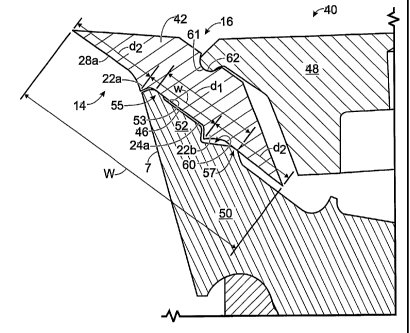
Now turning to Figure 3, an apparatus 40 for clamping a knife 42 according to
the
present invention is shown. The width "w" of a pressure-applying portion 46 of
the
apparatus 40 is narrower than the corresponding pressure-applying portion 32
of the
apparatus 10. Preferably, according to the invention, the width "w" and the
corresponding
distance "w" (measured tip-to-tip) between the deflector ridges 22 of the
knife 42 is about
0.54" or less for a knife 42 having a total width "W" of about 1.76 to 1.8."
The width "w"
may be scaled for larger or smaller knives by normalizing it according to the
overall width
"W", i.e., forming the ratio "w/W," to provide a result that is no more than
about 0.31.
Decreasing the width "w" decreases the overall width "W" of the knife 42 with
respect to the knife 12, providing the outstanding advantage of decreasing
manufacturing
cost for the knife for the reason mentioned above.
The knife 42 is clamped between an outer clamping member 48 and a counterknife
50. According to the invention, an outer surface the counterknife 50 includes
a toe 52 that,
corresponding to the pressure-applying portion 46, has a narrower width than
that of the
CA 02451362 2003-12-19
WO 03/008162 PCT/US02/20946
corresponding prior art toe 32 (Figure 1). The toe 52 includes a first contact
surface 55
adjacent the recess, or one of the deflector ridges 22 of the knife, which
establishes a first
point of contact between the knife and the apparatus 40.
Also according to the invention, a second contact surface 57 is provided on
the
counterknife 50 that is outside the recess, or space between the deflector
ridges of the
knife. The distance "dl" between the first contact surface 55 and the second
contact
surface 57 (outside edge to outside edge) is preferably as great as or may be
greater than the
width "w" of the prior art toe 32 (Figure 1), to ensure that decreasing the
width of the knife
does not destabilize contact between the knife and the counterknife.
In a preferred embodiment of the invention, "d~" is about 0.70" for a knife
having
an overall width "W" of about 1.76 - 1.8", or between about 0.65" to 0.75,"
for a
normalized value in the range of about 0.036 - 0.043. The distance "d2"
between the
deflector ridges and the respective cutting edges remains the same as in the
prior art to
ensure that the performance of the chipping apparatus employing the knife is
not impacted.
Turning to Figure 4, a prior art counterknife 72 manufactured and marketed by
Key
Knife, Inc. establishes a contact surface 74 that provides a surface of
contact with a
corresponding prior art knife 70 having an overall width "W" of 2.03" that
extends outside
the space defined between the deflector ridges of the knife 70 a distance "D
1" of about
0.58" from the nearest deflector ridge. However, as mentioned, the present
inventor has
recognized that changing the knife and attack angles 62 and 61, rather than
the knife and
relief angles as in the prior art, provides the most effective control over
the quality of wood
chips, and that the magnitude of D1 severely limits or prevents this
possibility.
11
CA 02451362 2003-12-19
WO 03/008162 PCT/US02/20946
Figure 5 shows the knife 70 wherein the knife angle 6a for both cutting edges
30a
and 30b is modified by grinding the lower knife-edge joining portions 28,
resulting in an
increased knife angle 63 for both cutting edges and an increased attack angle
61 for the
cutting edge 30a when the knife is clamped in the chipping apparatus. As
shown, the
grinding causes separation of the lower knife-edge joining portion 28b
associated with the
cutting edge 30b from the contact surface 74, destabilizing the contact
between the knife
and counterknife.
To solve this problem, the contact surface 74 is moved closer to the deflector
ridges
22. Turning to Figure 6, the knife 42 of the present invention includes flat
portions
(hereinafter "flats") 64 corresponding to each deflector ridge outside the
channel between
the deflector ridges. The flats are substantially parallel to the pressure-
applying channel
surface 24a (Figure 2A), and serve as a convenience in manufacturing. However,
according to the invention, these flats are used for the additional purpose of
providing a
region of contact for the contact surface 57 of the counterknife 50 (Figure
3).
In a preferred embodiment of the invention, the outer end of the flat 64 is
located a
distance "s" from the recess, or the tip "T" of the deflector ridge, that is
equal to the typical
radius "r" of 0.25" of the deflector ridge plus a distance 0.10" corresponding
to the width of
the flat, or about .35." For a knife 42 having an overall width "W" (Figure 3)
of about 1.8",
this normalizes to a ratio "s/W" of 0.194.
Preferably, the ratio "s/W" is no more than about 0.22, and may be
significantly
less than 0.194 where the recess is defined more sharply than by use of the
radiused
deflector ridge. However, persons of ordinary skill in the art will appreciate
that the
12
CA 02451362 2003-12-19
WO 03/008162 PCT/US02/20946
distance "s" may be increased and the present capability to alter the knife
and attack angles
may be retained by sacrificing the width of the lower-knife-edge joining
portions 28.
However, it is believed that the prior art ratio of about 0.29 is too large to
be satisfactory
for the purposes described herein. It may be noted that the ratio s/W also
defines the
.. m~imum distance that the contact surface 57 may be located from the recess,
or the
nearest deflector ridge, since the contact surface 57 makes contact with one
of the flats.
Each flat extends preferably between 0.08" and 0.12" for the 1.8" wide knife
42,
which normalizes to a ratio within the range of about 0.045 to 0.065.
Preferably, two flats
are symmetrically provided, corresponding to each of the deflector ridges, so
that the knife
may be turned end-to-end with substantially identical functionality.
Referring back to Figure 3, the outer surface 53 of the counterknife is
preferably
relieved, with respect to a plane defined by the contact surfaces 55 and 57,
for the entire
distance between the contact surfaces to provide for just two points of
contact between the
knife and counterknife 50, to provide for greater stability of contact and
extreme
insensitivity to dimensional variations between the parts. Moreover, at a
recess 60, the
outer surface 53 is relieved to a greater degree to accommodate one of the
deflector ridges.
The deflector ridges are preferably substantially identical, and the recess 60
is preferably
shaped and dimensioned to wholly receive one or the other, so as to leave a
clearance
therebetween.
The outer clamping member 48 preferably includes an interlocking feature 61
(Fig.
3), such as a projection, adapted to fit into corresponding interlocking
feature 62 (Figs. 2A,
2B) of the back side 16 of the knife, such as a recess or, more particularly
in the preferred
13
CA 02451362 2004-10-O1
embodiment, a groove which is preferably semi-cylindrical or, more preferably,
substantially half cylindrical. This establishes a third location of contact
for clamping
the knife, and also provides the outstanding advantage of holding the knife to
the outer
clamping member for changing the knife when the outer and inner clamping
members
are opened with respect to one another, in orientations of the knife wherein
the knife
rests on the outer clamping member when the knife is unclamped in the chipping
apparatus.
Turning to Figure 7, a side elevation of the knife 42 modified for use in the
apparatus of Figure 3 is shown. The knife is modified by grinding, preferably,
both of
the lower knife-edge joining portions 28a and 28b, so that the knife can be
turned end-
to-end to permit consecutive use of two cutting edges. The knife-edge joining
portion
28a prior to modification is shown in solid lines, and same portion as
modified (28a') is
shown in dotted lines. With reference to a given relief angle 63 as defined by
the
apparatus, it can be seen that the original attack angle 6,o is increased by
the grinding, to
e,;.
Conversely, with reference now to Figure 8 wherein another side elevation of
the
knife 42 is shown, the knife may be modified by grinding the lower knife-edge
joining
portions to form an undercut 80, to permit decreasing the attack angle 6,e to
6,d.
Turning to Figure 9, the knife 42 of Figure 7 as modified by increasing the
knife
and attack angles is shown supported by a counterknife SO according to the
present
invention. It can be seen that, due to the placement of the contact surface 57
for making
contact between the knife and counterknife, the same counterknife used to
support the
14
CA 02451362 2003-12-19
WO 03/008162 PCT/US02/20946
unmodified knife can support the modified knife. Moreover, because the contact
surface
57 is outside the space between the deflector ridges, greater contact
stability is provided.
Similarly, turning to Figure 10, the knife 42 of Figure 8 as modified by
decreasing the knife
and attack angles is shown supported by the same counterknife 50, providing
for the same
outstanding advantages. -
According to the above principles, a series of knives is preferably provided
having
varying knife angles. A knife having a selected base angle, e.g., 31°,
is provided in the
series wherein the lower knife-edge joining portions 28a and 28b are arranged
to be
coplanar, and lc~uves wherein this condition is not met may be provided in
advance, rather
than obtained from the base knife at the point of use by grinding. Other
knives in the series
may have angles that vary above the base angle (corresponding to Figures 7 and
9) and
below the base angle (corresponding to Figures 8 and 10) in selected, e.g.,
2°, increments.
It is to be recognized that, while a specific method and apparatus for
clamping a
knife has been shown and described as preferred, other configurations could be
utilized, in
addition to configurations already mentioned, without departing from the
principles of the
invention.
The terms and expressions which have been employed in the foregoing
specification are used therein as terms of description and not of limitation,
and there is no
intention of the use of such terms and expressions to exclude equivalents of
the features
shown and described or portions thereof, it being recognized that the scope of
the invention
is defined and limited only by the claims which follow.