Note: Descriptions are shown in the official language in which they were submitted.
~
h
CA 02451436 2006-04-28
_...~ttomey Docket Nfl: 1139=001 WO
Express Mail Label No. EV323888137US
~4
AUTOMOTIVE VEHICLE SEAT INSERT
10 FIELD OF THE INVENTION
The present invention relates generally to automotive vehicle seats,
and more particularly to an insert for providing heating, cooling, ventilation
or
a combination thereof to a seat of an automotive vehicle.
BACKGROUND OF THE INVENTION
For many years the transportation industry has been concerned with
designing seats for automotive vehicles that provide added comfort to
occupants in the seats. Various innovations in providing seating comfort are
discussed in U.S. Patent Nos. 6,064,037; 5,921,314; 5,403,065; 6,048,024
and 6,003,950.
In addition, other innovations in providing seating comfort are
discussed in U.S. Patent Publication No. 2002/0096931, published July 25,
2002 and entitled "Ventilated Seat" and U.S. Patent No. 6, 629,724, issued
October 7, 2003 and entitled "Ventilated Seat".
In the interest of continuing
such innovation, the present invention provides an improved seating system,
insert for a seat or both, which are preferably suitable for employment within
or as part of an automotive vehicle seat and which assist in providing comfort
control to an occupant in the seat.
1
CA 02451436 2003-12-23
Attorney Docket No. 1139-001 WO
Express Mail Label No. EV3238881371JS
SUMMARY OF THE INVENTION
According to the present invention, there is disclosed a seat insert, a
method of forming the seat insert and a ventilated seat that is preferably
suitable for an automotive vehicle. The insert preferably includes a forward
layer, a rearward layer and a middle layer, although greater or fewer layers
may be included. When included, the forward layer typically includes a first
barrier sub-layer, a heater sub-layer, a plurality of openings or a
combination
thereof. In preferred embodiments, the first barrier sub-layer is formed of a
plastic material, the heater sub-layer is formed as a lay-wire heater or both.
The rearward layer, when included, has a second barrier sub-layer, an
opening or both. In a preferred embodiment, the second barrier sub-layer is
formed of a plastic material like the first barrier sub-layer. The middle
layer
typically includes a spacer sub-layer defining an open space. In a preferred
embodiment, the spacer sub-layer is formed of interwoven polymeric strand
material. An air mover (e.g., a blower) is attached to the insert and is
preferably at least partially disposed within the at least one opening of the
rearward layer, although not required. The air mover is in fluid communication
with the plurality of openings in the forward layer, the open space of the
spacer sub-layer or both.
During formation of the insert, the first barrier sub-layer is preferably
sealingly attached to the second barrier sub-layer about a periphery of the
insert, although other attachments may be employed. The blower is
preferably configured to pull air through the plurality of openings in the
forward layer and through the open space of the spacer sub-layer, but it may
also push air through these areas.
When assembled to a seat (e.g., a vehicle seat), the seat preferably
includes a seat cushion component and a seat backrest component. At least
one of the components is typically ventilated by the insert and each
ventilated
component typically includes an air-permeable trim surface at occupant
contact areas of the seat. The insert is preferably located beneath the trim
surface of each ventilated component.
2
CA 02451436 2003-12-23
Attorney Docket No. 1139-001 W4
Express Mail Label No. EV323888137U5
BRIEF DESCRIPTION OF THE DRAWINGS
The features and inventive aspects of the present invention will
become more apparent upon reading the following detailed description, claims
and drawings, of which the following is a brief description:
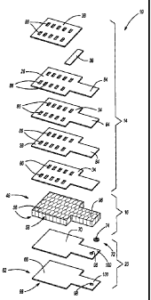
Fig. 1 is a blown up perspective view of a seat insert in accordance
with an exemplary aspect of the present invention;
Fig. 2 is a flow diagram for producing seat inserts in accordance with
an exemplary aspect of the present invention;
Fig. 3 is a partially cut-away elevational view of the seat insert of Fig. 1
after assembly of the insert;
Fig. 4 is a sectional view of the insert of Figs. 1 and 3 taken along line
4-4 in Fig. 3;
Fig. 5 is a perspective view of an exemplary blower suitable for
application in the insert of the present invention; and
Fig. 6 is a sectional view of the insert attached in an exemplary manner
to a seat of an automotive vehicle according to the present invention.
DETAILED DESCRIPTION OF THE INVENTION
The present invention is predicated upon providing an insert suitable
for placement within an automotive vehicle seat to provide heating, cooling,
ventilation or a combination thereof to an occupant in the seat. The insert
will
include at least one layer, but preferably includes multiple (e.g., three)
layers
and each of the layers may include one or more sub-layers. For example,
one of the layers preferably incorporates a heater or heater sub-layer into
the
insert. One or more of the layers also preferably incorporates a plastic film
sub-layer for assisting in lamination of the layers, for providing a gas
barrier or
both. It is also preferable for one or more of the layers to provide a spacer
sub-layer for providing open space within the insert. Additionally, a blower
may be incorporated into the insert for providing fluid flow through the
insert.
Referring to Figs. 1 and 3-5, there is illustrated an exemplary insert 10
suitable for placement within a seat of an automotive vehicle. The insert 10
preferably includes a plurality of layers that may be separate but are
preferably attached to each other to form the insert. In the embodiment
shown, the insert 10 includes a first or forward layer 14 (e.g., the layer of
the
3
CA 02451436 2006-04-28
Attorney Docket No. 1139-001 WO
Express Mail Label No. EV323888137US
insert configured to be closest an occupant of the seat), a second or middle
layer 16 and a third or rearward layer 20 (e.g., the layer of the insert
configured to be furthest from the occupant of the seat).
It is preferred that one of the layers 14, 16, 20 includes a heater. In the
embodiment depicted, the forward layer 14 includes a heater sub-layer 26,
which is preferably laminated to a gas barrier sub-layer 28 (e.g., a film, a
textile or otherwise) although such film is not necessarily required. Various
different types of heaters are suitable for incorporation into a car seat and
it is
contemplated that any of such heaters may be incorporated into the insert 10
of the present invention. Such heaters typically incorporate flexible
electrical
heating elements that are preferably thin, flat, non-obtrusive or a
combination
thereof. As examples, a lay-wire heater, a carbon fiber heater, a positive
thermal coefficient (PTC) heater, a thermoelectric heater or the like, which
are
typically supported with a backing (e.g., a cloth or fabric type backing) may
be
used within the insert. In a preferred embodiment, the heater sub-layer 26 is
a carbon fiber type heater with a backing (e.g., a nonwoven layer). One
exemplary preferred heater is sold under the tradename CARBOTEX~ and
commercially available from W.E.T Automotive Systems, Inc. in Germany
and/or FTG Fraser-Technik GmbH, Schleizer Strasse 56-58, D-95028
Hot/Saale, Germany. An example of such a heater is disclosed in U.S. Patent
6,064,037, issued May 16, 2000
When included, the barrier sub-layer 28 is typically formed of a plastic
or polymeric material that softens or melts upon exposure to heat to assist
the
sub-layer 28 to adhere to one or more other layers or sub-layers.
Alternatively, the barrier sub-layer 28 may be formed of fabrics, woven
materials (e.g, goretex or microfibers), nylon, closed pore foam or other
materials. Preferably, the barrier sub-layer 28 is substantially impermeable
to
fluids and particularly air such that the sub-layer 28 can assist in forming,
an
air barrier as will be described further herein. Dimensionally, for a film
barrier
sub-layer, it is preferable for the film thickness to be about 0.1 mm to about
2.0 mm thick and more preferably about 0.7 mm to about 1.0 mm thick. Of
course, it is contemplated that the film sub-layer 28 may have a variable
thickness and may be outside of the aforementioned ranges.
4
CA 02451436 2003-12-23
Attorney Docket No. 1139-001 WO
Express Mail Label No. EV323888137US
The first layer 14 may also include one or more buffer sub-layers, one
or more adhesives or adhesive sub-layers, one or more tape sub-layers, one
or more porous foam layers or a combination thereof. Adhesive may be
supplied in layers, drops or in a variety of other configurations. Preferably,
the
buffer layer is at least partially formed of an insulating material.
In the preferred embodiment depicted, the first layer 14 includes two
adhesive sub-layers 34, one strip of tape 36 and one buffer sub-layer 38. The
adhesive sub-layers 34 are preferably formed of a hot melt adhesive although
not necessarily required. The adhesive may be provided as a web or
otherwise and may be continuous or non continuous (e.g., may be applied in
drops, dabs or the like). The adhesive sub-layers may include polyamides,
polyesters, elastomers, urethanes, olefin polymers or a combination thereof.
Moreover, the adhesives may be formulated as desired for particular
processing parameters or conditions. Preferably, the adhesive sub-layers are
substantially free of anti-blocking solutions, blowing additives, process
contaminants or the like which might interfere with adhesive performance. As
an example, one suitable hot melt adhesive is commercially available as a
non-woven web under the tradename SPUNFAB~ from Spunfab, Ltd. 175
Muffin Lane, Cuyahoga Falls, OH 44223.
The buffer sub-layer 38 in the embodiment depicted is a layer of gauze
which is capable of protecting the heater layer 20 although various
alternative
protective materials may be used such as cloth, fleE;ce or the like. The tape
36 is preferably tacky on two sides.
According to an alternative embodiment, it is contemplated that the first
layer 14 may also include an air-permeable layer (not shown) between buffer
sub-layer 38 and an occupant of the seat. The air-permeable layer, which
may be any one of a variety of air-permeable materials (such as reticulated
foam, for example) may be able to help distribute air under the occupant.
One of the layers 14, 16, 20, preferably the middle layer 16, includes a
spacer sub-layer 48 formed of a spacer material. The spacer material may be
provided as a variety of synthetic materials such as plastic or polymeric
materials, padding and stuffing materials, lining and carrier materials or the
like. Preferably, the spacer material creates a sub-layer 48 that functionally
provides open space within the sub-layer while remaining at least partially
5
CA 02451436 2003-12-23
Attorney Docket No. 1139-001 WO
Express Mail Label No. EV323888137US
pliable or flexible between the first and third layers 14, 20. As one example,
the spacer sub-layer may be provided as a plurality of rubber, foam plastic or
other members or fibers. The members or fibers are preferably spaced apart
from each other to provide open space therebetween while still being close
enough together to provide cushion and support. As another example the
spacer sub-layer 48 may be formed of a 3-dimensional spacer fabric structure
or material.
In the preferred embodiment depicted, the middle layer 16 includes
only the spacer sub-layer 48, however, it is contemplated that additional sub
layers (e.g., adhesive sub-layers) or other materials (e.g., adhesives) may be
incorporated into the middle layer 16. The particular sub-layer 48 shown is
formed of polymeric (e.g., polyester) strand material that is interwoven to
provide opposing honeycomb structures 56 (e.g., fabric panels), which are
interconnected by several additional polymeric strand materials to provide
open space 58 between the structures 56 while still providing cushion and
support. As an example, one preferred material is sold under the tradename
3MESH~ and is commercially available from Muller 'Textil GmbH, Germany or
Miiller Textiles, Inc., Rhode Island, USA.
In another of the layers 14, 16, 20 of the insert 10, preferably the
rearward layer 20, there is included an outer protective or buffer sub-layer
and
another barrier sub-layer. In the embodiment shown, one integrated sub-layer
62 provides the both the barrier sub-layer 66 and the outer protective sub
layer 68 although they may be provided separately. The barrier sub-layer 66
for the rearward layer 20 may be the same or different than the barrier sub
layer 28 of the forward layer 14.
Preferably, the protective sub-layer 68 is formed of a fleece material,
however, various other materials may be used such as gauze, cloth, fabric or
the like. It is also preferable for the rearward layer 20 to include an
adhesive
or adhesive sub-layer 70 similar to or the same as those discussed in relation
to the forward layer 14. According to a preferred embodiment, the adhesive
sub-layer 70 is provided integrally with the integrated sub-layer 62.
In a highly preferred embodiment, an attachment component 72 is
included in one of the layers 14, 16, 20. The attachment component 72
shown in Fig. 1 is a frame member that preferably defines an opening or
6
CA 02451436 2003-12-23
Attorney Docket No. 1139-001 WO
Express Mail Label No. EV323888137US
through-hole 74. It is contemplated that the frame member may be in a
variety of configurations (e.g., annular, rectangular, square, geometric or
otherwise) and may be formed of a variety of preferably rigid or semi-rigid
materials (metal, plastic or the like).
Notably, several of the materials of the various layers and sub-layers of
the insert 10 may be environmentally friendly. For example, and without
limitation, the materials of the spacer sub-layer 48, the buffer and
protective
sub-layers 38, 68 and the barrier sub-layers 28, 66 may be recyclable.
Assembly
Generally, for forming a vehicle seat insert according to the present
invention, it is contemplated that the various layers and sub-layers of the
insert as described above may be combined in a variety of sequences and
according to a variety of protocols and technique. Thus, the order in which
the various layers and sub-layers are combined and the techniques of
combining should not in any way limit the present invention unless such order
or techniques is specifically claimed. Moreover, it is also contemplated that
there may be greater or fewer layers and that each layer may include greater
or fewer sub-layers.
According to a preferred method, the sub-layers of the front or first
layer and the third or rearward layer are each laminated separately followed
by laminating the front layer to the rearward layer with the middle layer in
between. Referring to Figs. 1 and 2, the first Layer 14 is formed according to
a
preferred method by feeding the various sub-layers 38, 26, 28 to a laminator
80 (e.g., a belt and roller laminator).
Although the manner in which the sub-layers 38, 26, 28 are fed to the
laminator 80 may be varied, the preferred embodiment has the buffer sub-
layer 38 and one of the adhesive sub-layers 34 as the outer sub-layers on the
outer sides of the first layer 14. The barrier sub-layer 28 and the heater sub-
layer 26 are directly inside of the outer sub-layers and, as shown, the other
adhesive sub-layer 34 is between the barrier sub-layer 28 and the heater sub-
layer 26. Preferably, the tape 36 is integrated into the first layer 14
between
the buffer sub-layer 38 and the heater sub-layer 26 such that the tape 36 may
be used to form a pocket for securing a wire harness 40 to the insert 10. It
is
7
CA 02451436 2003-12-23
Attorney Docket No. 1139-001 WO
Express Mail Label No. EV323888137US
also preferable for some amount of adhesive to be applied between and
adhere the buffer sub-layer 38 and the heater sub-layer 26 to each other.
During the lamination process, it may be preferable for the laminator 80
to expose various portions of the first layer 14 to different temperatures.
For
the embodiment illustrated, it is preferred that the laminator 80 expose a
first
side of the first layer 14 (e.g., the side that includes the buffer sub-layer
38
and the heater 26) to a higher temperature while exposing a second opposite
side of the first layer 14 (e.g., the side having the film sub-layer 28 and
outermost adhesive sub-layer 34) to a lower temperature. Depending upon
the materials used, the difference between the higher and lower temperatures
is preferably between about 5°C and about 150°C, more preferably
between
about 10°C and about 100°C and even more preferably between
about 20°C
and 80°C. in this manner, the central adhesive sub-layer 34 of the
first layer
14 is exposed to higher temperatures and is induced to more substantially
melt and adhere the barrier sub-layer 28 to the heater sub-layer 26. At the
same time, the outermost adhesive sub-layer 34 of the first layer 14 is
maintained at a lower temperature than the central adhesive sub-layer 34
thereby avoiding excess melting of the outermost adhesive sub-layer 34.
The sub-layers 36, 26, 28 are preferably fed to the laminator 80 from
rolls or otherwise and are cut to shape to form the first layer 14 after
lamination. The first layer 14 may be cut to nearly any desired shape or
configuration. In the illustrated embodiment, the first layer 14 is cut to be
generally rectangular and to include an extension 84 and a plurality of
through-holes 86. In Fig. 1, the through-holes 86 are arranged in a generally
rectangular configuration and are each substantially the same size. In Fig. 3,
however, the through-holes 86 are shown in a preferred configuration as
progressively becoming larger from one side of the insert 10 to another.
Referring to Fig. 3, the through-holes 86 preferably increase in size as
the distance of the holes from the blower increases. This increase in size
provides a more uniform flow of air throughout the insert 10. It is believed
that
the increase in the total cross-sectional area of through-holes 86 as the
distance from the blower increases allows air to enter or exit the openings at
a
more uniform rate than if the cross-sectional areas of through-holes at
difiFerent distances from the blower were equal. The increase in cross-
8
CA 02451436 2003-12-23
Attorney Docket No. 1139-001 WO
Express Mail Label No. EV323888137US
sectional area can be achieved by increasing the size of the holes, the
number of holes, or a combination thereof. Finally, the increase in the cross-
sectional area need not be a strict progression for each and every through-
hole, rather, the through-holes in a region further from the blower should
have
a greater cross-sectional area than the through-holes in a region closer to
the
blower. Through-holes 86 may also be provided in a variety of different
patterns. According to one preferred embodiment, through-holes 86 are
provided in a substantially "U" shaped configuration corresponding to the legs
and seat of the occupant. According to an alternative embodiment, through-
holes 86 may be provided in a linear or straight line pattern (for example, to
correspond to the back of an occupant) or in a variety of other patterns. Such
pattern may be influenced by the portion of the seat in which the insert is
used
and the portion of the body of the occupant nearest the insert. According to
other alternative embodiments, the number, size, shape, and pattern of
through-holes 86 may vary.
The rearward layer 20, like the front layer 14, is also preferably formed
by attaching it sub-layers 62, 70 in a lamination process. Referring again to
Figs. 1 and 2, the barrier sub-layer 66, the protective sub-layer 68 and the
adhesive sub-layer 70 are fed to a laminator 90 (e.g., a belt laminator) such
that the barrier sub-layer 66 is between and attached to the adhesive sub-
layer 70 and the protective sub-layer 68. Thereafter, the rearward layer 20 is
cut to have a shape substantially corresponding to the first layer 14. Of
course, it is contemplated that the rearward layer may be cut into a variety
of
other configurations as well. Preferably, the rearward layer 20 includes a
through-hole 98 as shown in Fig. 3 through an extension 100 of the rearward
layer 20 that corresponds to the extension 84 of the first layer 14. It is
contemplated, however, that the through-hole 98 may also be formed in the
forward layer 14 if desired.
Once the middle layer 16 has been appropriately cut or otherwise
shaped to the proper configuration, which preferably corresponds to the
forward and rearward layers 14, 20, each of the layers 14, 16, 20 are
laminated together to attach the layers 14, 16, 20 to each other. As shown,
the middle layer 16 may be cut to include an extension 96 corresponding to
the extensions 84, 100.
9
CA 02451436 2003-12-23
Attorney Docket No. 1139-001 WO
Express Mail Label No. EV323888137US
In the preferred embodiment, the layers 14, 16, 20 are laminated in a
stationary lamination device 104 at elevated temperatures such that the
adhesive sub-layer 70 of the rearward layer 20 and the outermost adhesive
sub-layer 34 of the forward layer 14 both~adhere and attach the forward layer
14 and the rearward layer 20 to the middle layer 16 (e.g., the honeycomb
structure). At the same time, it is preferred that the barrier sub-layer 28 of
the
front layer 14 and the barrier sub-layer 66 of the rearward layer 20 be
adhered
to one another about an outer peripheral strip 106 of the insert 10. It is
also
preferred that the attachment component 72 be sandwiched and attached
between at least portion of the rearward layer 20 and the middle layer 16
although the attachment component may be otherwise attached (e.g., retrofit,
fastened, or the like).
The strip 106 may have a width as high as four (4) centimeters or
greater. Preferably, the strip is between about 0.2 cm and about 3 cm and
more preferably between about 1.0 cm and 2.0 cm. Advantageously, the
adhesive sub-layers 34, 70 and the outer laminated peripheral strip 106
separately and together assist in forming the insert 10 as a tightly
integrated
unit wherein the layers 14, 16, 20 are substantially immobile relative to each
other.
While pre-cutting the layers 14, 16, 20 followed by laminating the
peripheral edges of at least two of the layers 14, 20 have been discussed, it
is
contemplated that cutting of the layers 14, 16, 20 and laminating of the
layers
may be integrated into a single processing step. For example, it is
contemplated that supplies (e.g., rolls) of each of the layers 14, 16, 20 may
be
provided to a machine that laminates outer edges of each of the layers 14, 16,
20 together for forming the peripheral strip 106 as the supplies continuously
or
intermittently provide the layer 14, 16, 20 to the machine. Thus, inserts 10
may be formed by cutting the inserts 10 with the peripheral strip 106 from the
laminated layers 14, 16, 20 and such cutting may be performed by the
laminating machine or by another cutting machine or device. In such an
embodiment, it is contemplated that the through-holes in the forward layer 14
and the through-hole in the rearward layer may be formed prior to, during or
after lamination forming the outer peripheral strip 106,.
CA 02451436 2003-12-23
Attorney Docket No. 1139-001 WO
Express Mail Label No. EV323888137US
Although laminating the edges of the film together and the use of
adhesive layers have been found particularly advantageous, it is
contemplated that other methods of attachment may also be employed in
conjunction with the laminated edges or separately. For example a robot may
be employed to apply a variety of adhesives such as hot-melt, heat activated,
encapsulated or other types of adhesives. In one preferred alternative, an
encapsulated adhesive may be applied to a first layer followed by breaking
the encapsulated adhesive in close time proximity to attaching a second layer
to the first layer. In other preferred embodiments, it is contemplated that
the
plastic films may be fused together with other techniques such as those used
for book binding. Moreover, mechanical attachments (e.g., snaps, zippers,
sewing, stitching, stapling or the like) may be used alone or in conjunction
with the plastic films and adhesives.
During final assembly 110, the wire harness 40 is preferably inserted
within the pocket formed by the tape 36 or otherwise attached to the insert
10.
Also, a blower, the housing 120 of which is shown in Fig. 5, is preferably
attached to the attachment component 72 of the insert 10. In the embodiment
shown, the housing 120 include flanges 124 suitable for snap-fitting the
housing 120 to the attachment component 72. In this manner, the blower can
be attached to the rest of the insert 10 and can be placed in fluid
communication with the through-holes 86 of the first layer 14, the open space
58 of the middle layer 16 and the through-hole 98 of the rearward layer 20.
Advantageously, the attachment component 72 and flanges 124 provide a
unique and efficient method of attaching the blower to the insert 10. It is
contemplated however, that various other methods of attachment (e.g.,
fasteners, sewing, mating threaded attachments, quick connects or the like)
may be used to attach the blower to the insert 10. It is also contemplated
that
the attachment component 72 and the housing 12U and flanges 124 of the
blower may be varied within the scope of the present invention.
For assembly of the insert 10 to a vehicle seat (not shown), the insert
10 is preferably connected (e.g., sewn, adhered or otherwise attached) to a
portion of the seat such as the cover (e.g., a perforated leather cover) or to
a
cushion (e.g., foam) of the seat. In one preferred embodiment, a seat cover
may be configured to include a pocket for receiving the insert 10.
11
CA 02451436 2003-12-23
Attorney Docket No. 1139-001 WO
Express Maif Label No. EV323888137US
Alternatively, it is contemplated that hook and loop fasteners may be utilized
to attach the insert 10 to portions (e.g., the cover or foam) of the seat.
The insert 10 is preferably positioned in the seat such that the first
layer 14 is closer to the outer seat cover relative to the rearward layer 20
although not necessarily required. It is also preferable for an extension 139
formed by the extensions 84, 96, 100 of the layers 14, 20 to extend behind the
cushion of the seat such that the blower may be attached to a portion of the
frame of the vehicle seat. Preferably, the extension 139 is a tubular
structure
for providing fluid communication between the open space of the spacer layer
48 and the blower. Additionally, the wire harness 40, the heater sub-layer 26,
the blower or a combination thereof are preferably connected in signaling
communication with a control unit 130 andlor each other. The control unit 130
may be separate from or integrated into the vehicle.
In one embodiment referring to Figs. 3, 4 and 6, the insert 10 is formed
with one or more (e.g., three) through-holes 140 that extend through the
layers, sub-layers or both of the insert 10 such that the through-holes 140
extend entirely or substantially entirely through the insert 10. Preferably,
the
insert 10 (e.g., the barrier layers 28, 66) have a seat 141 about the through-
holes 140 for substantially preventing direct fluid communication between the
through-holes 140 and the open space 58 within the insert 10. In the
embodiment depicted, the barrier sub-layers 28, 66 are attached to each other
during the lamination process to form a substantially air-tight seal 141 about
the through-holes 140.
Advantageously, the through-holes 140 can assist in the assembly of
the insert 10 andlor a seat cover 142 to a seat 144 of an automotive vehicle.
As shown, for each through-hole 140, a portion 148 (e.g., a cushion layer, a
felt layer, a leather layer, combinations thereof or the like) of the seat
cover
142 is extended through the through-hole 140 and is attached to foam 154 of
the seat 144. In the embodiment depicted, the portion 148 is attached to the
foam 154 by wrapping or otherwise attaching the portion 148 about a member
162 (e.g., a bar or wire) that is attached to (e.g., at least partially
imbedded
within) the foam 154. Additionally, one or more loops 166 (e.g., metal loops)
are integrated with the portion 148 and are looped about the member 162 for
assisting in attaching the portion 148 to the member 162.
12
CA 02451436 2003-12-23
Attorney Docket No. 1139-001 WO
Express Mail Label No. EV323888137US
It shaft be appreciated that, in embodiments alternative to the one
depicted, a variety of materials or members such as wire, thread, stitches,
fasteners, foam or the like may extend through the through-holes 140 in the
insert 10 for assisting in the attachment of the seat cover 142, the insert 10
or
both to the other components of the seat 144. Moreover the materials or
members may be connected to the seat cover, the foam, the seat frame, other
portions of the seat or vehicle or the Pike depending on the desired
configuration. It is also contemplated that other attachment methods such as
the use of alternative fastening devices may be employed in addition to or
alternative to the through-holes 140. For example, hook and loop fasteners,
sewing, adhesives or other fastening devices or mechanisms may be
employed to locate the insert 10 relative to the seat cushion, the seat cover
142 or both.
While it is generally preferable that the layers 14, 16, 20 be
substantially coextensive with each other and that the rearward and forward
layers 14, 20 form a substantially continuous seal or peripheral strip 106
about the insert 10, it is contemplated that such is not the case. Thus, it is
contemplated that one or more of the layers 14, 16, 20 may be less than
coextensive with each other or non-existent. For example, the rearward layer
20 alone could provide a barrier sub-layer 66 that provides a sufficient
pathway for receiving air from the extension 139 and guiding air through the
spacer layer to the seat cover 142 or trim layers.
Operation
In operation, the insert of the present invention can preferably provide
heating, cooling, ventilation or a combination thereof to an occupant of a
seat
having the insert. In particular, if heat is desired, electric current can be
induced to travel through the heater sub-layer 26 by the control unit 130 or
otherwise such that the heater sub-layer 26 can provide heat to the occupant.
Alternatively, if cooling or ventilation is desired, the blower can be
operated via the control unit 130 or otherwise to pull air through the through-
holes 86 in the first layer 14 of the insert 10, through the open space 58 of
the
middle layer 48 of the insert 10 and through the through-hole 98 of the
rearward layer 20. Such air preferably flows at least partially past the
13
CA 02451436 2006-04-28
Axtom~y Docket No. 1139-001 WO
Express Mail Label No. .EV323888137US
occupant of the seat and through the seat cover (e.g., a pertorated leather
seat cover or cloth seat cover) thereby providing ventilation to the occupant
and providing convective heat transfer from the occupant to the flowing air.
Although, it may be preferable for only the heater sub-layer 26 or the
ventilation system to be running at one time, it is, contemplated that both
may
be operated simultaneously. Moreover, it is contemplated that both the heater
sub-layer 26 and the ventilation system may be operated at various levels
(e.g., 2 or more levels of output) such as by having a blower that can operate
at different levels or by having various levels of electricity flowing thought
the
heater sub-layer 26. It is also contemplated that the blowEr may push air into
the open space 58 of the insert 10 as well as pulling air from the open space
58.
It is also contemplated that one or more temperature sensors (e.g., a
thermostat) may be included adjacent the insert, the trim layer or the like.
Preferably, any temperature sensors are near the seat cover or the insert for
sensing a temperature closely related to (e.g., at or near) a temperature
being
experienced by an individual in the seat. Such temperature sensors may be
in signaling communication with the control unit 130 such that the control
unit
130 can control the blower 22, the heater layer 28 or both for attaining or
maintaining a desired temperature at areas adjacent the individual and/or the
temperature sensor. Moreover, the control unit 130 may be programmed with
instructions for commanding the blower 22, the heater layer 28 or both to
change output levels (e.g., turn on or turn off) if the temperature sensor
senses a temperature above or below one or more threshold levels:
Advantageously, the plastic film sub-layer-.s 28, 66 respectively of the
first and third layers 14, 20 provide a substantially gas-tight seal about the
middle layer 16 (e.g., the spacer sub-layer 48). In this manner, gas flow to
and from the open space 58 of the spacer sub-layer 48 is substantially
restricted to flowing through the through-holes 86, 98 of the first and third
layers 14, 20.
14
CA 02451436 2003-12-23
Attorney Docket No. 1139-001 WO
Express Mail Label No. EV323888137US
In a highly preferred embodiment, the through-hole 98, which may be
defined by the sub-layers 66, 70 of the rearward layer 20 or by the attachment
component 72, spans an area no greater than about 100 cm2 or higher, more
preferably between about 15 cm2 to about 60 cm2, even more preferably
between about 25 cm2 and about 40 cm2 and most preferably between about
30 cm2 and about 35 cm2 depending upon 'the size of the blower.
Advantageously, for maintaining more efFicient flow of air, the through-holes
86 on the front layer 14 may be sized to span areas, the sum of which, is
substantially similar (e.g., within 20 cm2, more preferably within 10 cm2 and
even more preferably within 5 cm2) to the area of 'the through-hole 98 in the
rearward sub-layer 20. Additionally, the open space 58 of the middle layer 58
may be sized such that nearly any cross-section substantially perpendicular to
airflow therethrough is also substantially similar (e.g., within 20 cmZ, more
preferably within 10 cm2 and even more preferably within 5 cm2) to the area of
the through-hole 98 in the rearward sub-layer 20.
The preferred embodiment of the present invention has been
disclosed. A person of ordinary skill in the art would realize however, that
certain modifications would come within the teachings of this invention.
Therefore, the following claims should be studied to determine the true scope
and content of the invention.