Note: Descriptions are shown in the official language in which they were submitted.
CA 02451531 2003-12-19
WO 03/005912 PCT/CA02/01068
SYRINGE AND NEEDLE FOR PREVENTING INADVERTENT DRUG INJECTION
FIELD OF THE INVENTION
The present invention generally relates to a syringe and needle, and a system
which
incorporates that syringe and needle in combination, for preventing
inadvertent injection of a
drag and more specifically relates to a syringe for spinal drag injection
which is incompatible
with a typical needle and a needle for spinal drag injection which is
incompatible with a
typical syringe.
BACKGROUND OF THE INVENTION
Drags mat' be injected into patients using a needle (or "cannula") by several
different
methods, including injection into a vein ("intravenously") or injection into
the fluid around
the seine ("spinally"), including intrathecally, epidurally and
intramedurally. Drag treatment
for particular ailments mat' at times require the injection of a drag in a
vert' specific marner.
For example, it is often of critical importance to ensure that drags intended
for intravenous
injection are rot mistakenly injected spinally and vice versa. It is also
important to ensure
that a drag contained in a syringe for injection in a particular marner is rot
mistakenly
attached to a needle used for inappropriate injection of that drag thereby
increasing the risk
Chat the drag will be mistalcenly injected in an inappropriate marner. For
example, to ensure
that a drag intended for intravenous injection stored in a syringe is rot
mistakenly attached to
a spinal needle and inj ected spinally.
This is of particular concern in the field of chemotherapy where vert' toxic
drags employed to
treat particular types of cancer must be injected in a vert' specific marner.
For example a
group of drags known as "vinca alkaloids" are extremely toxic when
administered in any
marner other than intravenously. If these drags are administered in any other
marner,
including spinally, these drags mat' be fatal to the patient.
SUBSTITUTE SHEET (RULE 26)
CA 02451531 2003-12-19
WO 03/005912 PCT/CA02/01068
2
There have been unfortunate occurrences of mistaken injection of a vinca
alkaloid drag used
in chemotherapy into a patients spinal region, rather than by the appropriate
method of
injection, that being intravenously. A syringe containing such a drag can be
accidentally
attached to a spinal needle and the drag injected spinally into the patient,
thereby causing
death or serious injury to the patient.
As well, a drag in a syringe which is intended to be injected spinally mat' be
attached to a
needle used for intravenous inj ection and the drag mistakenly inj ected
intravenously.
Many of these inadvertent injections can be attributed to human error in
either filling a given
syringe intended for spinal inj ection of drags with a toxic drag intended for
intravenous
inj ection or mixing up syringes containing various chemotherapy drags and
attaching a
syringe containing a toxic drag intended for intravenous inj ection to a
spinal needlè and
injecting that drag spinally into the patient.
As a result there is a significant need for the development of a syringe and
needle which mat'
be employed for spinal inj ection of a drag intended for spinal inj ection and
a system
incorporating a combination of that syringe and needle which will reduce the
risks inherent in
handling and injecting toxic drags meant to be injected only in a vert'
specific manner. The
present invention is intended to accomplish this by reducing the opportunity
for human error
in handling and injecting toxic drags in the appropriate manner into patients
receiving those
drags.
SUMMARY OF THE INVENTION
In ove embodiment of the invention a spinal syringe is operatively connectible
with a spinal
needle for spinal injection of a drag. The syringe is incompatible for
operative convection
with a connector of a typical needle. The spinal syringe includes a nozzle for
operatively
connecting the syringe to the spinal needle, the nozzle having a conduit
extending axially
therethrough for delivery of the drag from the syringe to the needle and
includes an outer tip.
The tip extends about an outer end of the conduit and is dimensioned to
contact the outer end
SUBSTITUTE SHEET (RULE 26)
CA 02451531 2003-12-19
WO 03/005912 PCT/CA02/01068
3
of the connecter of the typical needle te prevent operative comiection of the
spinal syringe
with the typical needle.
In another embodiment of the invention, a spinal needle is operatively
connectible with a
spinal syringe for spinal injection of a drag. The spinal syringe includes a
nozzle with a
conduit extending axially therethrough. The needle is incompatible for
operative convection
with the nozzle of a typical syringe, the nozzle having an outer tip. The
needle includes a
connecter cooperating with the nozzle of the spinal syringe te operatively
connect the spinal
syringe te the spinal needle te dispense the drag. The connecter includes an
outer end
dimensioned te contact the outer tip of the nozzle of the typical syringe te
prevent operative
correction of the spinal needle with the typical syringe.
Tn yet another embodiment of the invention, a spinal syringe and a spinal
needle combination
are operatively connectible with ove another for spinal injection of a drag.
The spinal syringe
is incompatible for operative convection with a connecter of a typical needle,
the connecter of
the typical needle having an outer end. The spinal needle is incompatible for
operative
convection with the nozzle of a typical syringe, the nozzle having an outer
tip. The spinal
syringe including a nozzle for operatively connecting the spinal syringe te
the spinal needle,
the nozzle having a conduit extending axially therethrough for delivery of the
drag from the
spinal syringe te the spinal needle and including an outer tip. The tip
extending about an
outer end of the conduit dimensioned te contact the outer end of the connecter
of the typical
needle te prevent operative convection of the spinal syringe with the typical
needle. The
spinal needle includes a connecter cooperating with the nozzle of the spinal
syringe te
operatively connect the spinal syringe te the spinal needle te dispense the
drag. The
connecter includes an outer end dimensioned te contact the outer tip of the
nozzle of the
typical syringe te prevent operative convection of the spinal needle with the
typical syringe.
In another embodiment a spinal syringe and needle for preventing the
inadvertent injection of
an intravenous drag spinally includes, in combination, a needle engagement
extension on the
spinal needle defming an opening of a first diameter, a syringe engagement
extension on the
spinal syringe having a nozzle of a second diameter, the syringe engagement
extension
SUBSTITUTE SHEET (RULE 26)
CA 02451531 2003-12-19
WO 03/005912 PCT/CA02/01068
4
engageable with the needle engagement extension to operatively connect the
needle to the
syringe. The first and second diameters are dimensioned such that a surface of
the syringe
engagement extension is in frictional engagement with a surface of the needle
engagement
extension, the first diarneter is smaller than the diameter of the nozzle of a
typical syringe and
the second diameter is larger than the diameter of the opening of a typical
needle.
In a further embodiment, a system and method for preventing the inadvertent
injection of a
spinal drug intravenously and an intravenous drug spinally includes, in
combination, a spinal
needle and a spinal syringe for holding and dispensing the drug to be injected
spinally, the
spinal drug operatively comiectable to the spinal needle. An intravenous and
intravenous
syringe are provided for holding and dispensing the drug to be injected
intravenously, the
intravenous syringe operatively connectable to the intravenous needle. The
intravenous
needle cannot be operatively connected to the spinal syringe thereby
preventing the
inadvertent injection of the drug in the spinal syringe through the
intravenous needle and the
spinal needle cannot be operatively connected with the intravenous syringe
thereby preventing
the inadvertent injection of the drug in the intravenous syringe through the
spinal needle.
In another embodiment, the spinal needle may include a first Luer lock portion
at an end of
the spinal needle and the spinal syringe can comprise a second Luer lock
portion at its end
which mates with the first Luer lock portion to operatively connect the spinal
needle with the
spinal syringe. In yet another embodiment, the intravenous needle may include
a first slip fit
portion on an end and the intravenous syringe may include a second slip fit
portion which
mates with the first slip fit portion of the intravenous needle to operatively
connect the
intravenous with the intravenous syringe.
BRIEF DESCRIPTION OF THE DRAWINGS
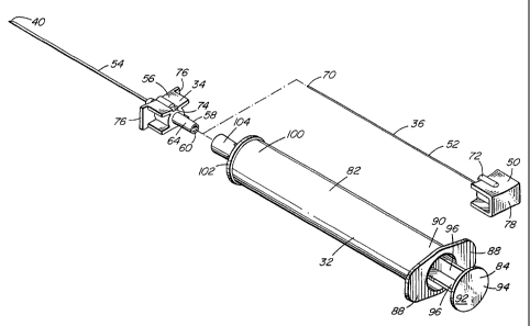
Fig 1 is a perspective view of a spinal needle, syringe and stylette;
Fig 2 is a fragmentary enlarged sectional view of the slip fit attachment end
of a spinal
syringe attached to the slip fit attachment end of a spinal needle;
SUBSTITUTE SHEET (RULE 26)
CA 02451531 2003-12-19
WO 03/005912 PCT/CA02/01068
S
Fig 3 is a fragmentary sectional view of the spinal needle and its
corresponding stylette;
Fig. 4 is a fragmentary sectional view of an attachment end of a typical
syringe commonly
used by. the medical profession adjacent to, but not attached to, the uniquely
dimensioned
attachment end of the spinal needle of the present invention;
Fig 5 is a fragmentary sectional view of a the attachment end of a typical
syringe commonly
used by the medical profession adjacent to, but not attached to, the uniquely
dimensioned
attachment end of the spinal needle of the present invention;
Fig 6 is a fragmentary sectional view of the uniquely dimensioned attachment
end of a syringe
of the present invention adj acent to, but not attached to, a standard
attachment end of a slip fit
needle commonly used by the medical profession; and
Fig 7 is a perspective illustration of a system for preventing the inadvertent
injection of a
spinal drug intravenous and an intravenous drug spinally.
DETAILED DESCRIPTION
Figure 1 depicts the uniquely dimensioned spinal syringe 32 and needle 34 of
the present
invention which are incompatible for use with a typical syringe and needle. As
used herein,
the term "typical syringe" and "typical needle" means a syringe and needle
typically used by
the medical profession meeting the ANSI/HIMA "American National Standard for
Medical
Materiel-Luer Taper Fittings-Performance MD70.1-1983 (Revision of ANSI 270.1-
1955).
The standard provides the following dimensions, including tolerances, for the
following
elements of "typical" syringes and needles:
COMPONENT SIZE (IN MILLIMETRES)
Inside diameter of the needle Minimum 4.270
socket opening,
at large end (Reference 120 of Maximum 4.315
Fig. 6)
SUBSTITUTE SHEET (RULE 26)
CA 02451531 2003-12-19
WO 03/005912 PCT/CA02/01068
6
Lug-to-lug diameter (Reference Minimum 7.73
158 of Fig.
6) . Maximum 7.83
Outside diameter of end of syringe Minimum 3.925
nozzle
(Reference 115 of Figs. 4 and Maximum 3.990
5)
Syringe 32 may be operatively connected to needle 34 for injection of the drag
in syringe 32
through needle 34 into a patient. Needle 34 includes cannula 54 which extends
from one end
of head 56. Stylette 36 may be inserted axially through cannula 54 needle 34
(as best seen in
Fig. 3) and includes generally rectangular-shaped head 50 attached at one end
of elongated
stylette portion 52; Stylette portion 52 is dimensioned to fit within hollow
inner opening of
needle 34.
Referring to Figures 1 and 3 head 56 includes extension 58 extending axially
from the end of
head 56 opposite to cannula 54. Extension 58 includes opeung 60 therein
extending axially
through head 56 and connecting to opening in cannula 54. Head 50 of stylette
36 includes
opening 62 defmed by inner surface 66 of flange 67 extending axially within
head 50 and
dimensioned to contact outer surface 64 of extension 58 such that, when
engaged with one
another as depicted in Figure 3, outer surface 64 of extension 58 lies
adjacent inner surface 66
of opening 62.
As best seen in Figure 3 stylette portion 52 is attached axially to head 50
through axial
extension 68. Stylette portion 52 is thereby retained rigidly within head 50
and extends
axially from extension 68 through openings 60 and 62 and then through cannula
54 of needle
34. The distal end of stylette opposite to the end attached to extension 68 is
angled to present
a sharp tip 70 at its outer end and stylette portion 52 is dimensioned in
length so as to be
generally co-terminus with tip 40 when stylette 36 is inserted into needle 34
as depicted in
Figure 3 and Figure 7.
Referring to Figure l, head 50 includes flange 72 extending in the direction
of tip 70. Head
56 includes a corresponding slot 74 which accepts tip 72 therein when stylette
36 is
positioned within needle 34. Cannula 54 includes tip 40 which is likewise
angled to present a
SUBSTITUTE SHEET (RULE 26)
CA 02451531 2003-12-19
WO 03/005912 PCT/CA02/01068
7
sharp point for ease of insertion of cannula 54 into the patient. When flange
72 is positioned
within slot 74 the angled portions of tips 40 and 70 are maintained in
alignment which
facilitates insertion of cannula 54 with stylette portion 52 into the patient.
Head 56 also includes a pair of opposed wing members 76 extending laterally
from the
longitudinal axis of needle 34. Head 50 includes platform 78 at the proximal
end of head 50
opposite to the end from which stylette portion 52 extends. Platform 78 and
wing member 76
are used to facilitate insertion of needle 54 with stylette 36 into the
patient as the part of the
appropriate procedure for inserting needle 34 into the patient for spinal
injection of a drug.
Wings 76 are used for gripping be the index and middle fingers of the person
inserting the
needle and platform 78 is used as a contact point for the thumb to assist in
the insertion of
needle 34 and stylette 36 into the patient.
Head 56 also includes cannula support extension 80 which serves to support
cannula 54
within head 56 thereby reducing the opportunity for lateral movement or
bending of cannula
54 when pressure is applied on tip 40 as cannula 54 is inserted into the
patient.
Referring to Figure 1 and Figure 2, needle 54 may be attached to syringe 32 in
order to
dispense the drug in syringe 32 through needle 34 into the patient. Syringe 32
includes
storage region 82 for storing the drug to be injected spinally into the
patient. Plonger 84
extends into first end 90 of region 82. Plonger 84 is used in a typical marner
and when
depressed within region 82 pots pressure on the drug in region 82 to cause the
drug to flow
through needle 34 into the spinal region of the patient. Syringe 32 also
includes end opening
86 extending axially from one end of storage region 82 to permit the drug
within storage
region 82 to exit syringe 32 through opening 86 into opening 60 of extension
58 when
plonger 84 is depressed.
Syringe 32 further includes a pair of opposed wing members 88 extending from a
first end 90
of region 82. Plonger 84 includes platform 92 on plate 94 which extends in a
plane
perpendicular to the longitudinal axis of plonger 84-. Plonger 84 further
includes longitudinal
axial extension ribs 96 extending from plate 94 at one end to inner sealed
resilient member
SUBSTITUTE SHEET (RULE 26)
CA 02451531 2003-12-19
WO 03/005912 PCT/CA02/01068
8
(rot shown) which provides a seal between plonger 84 and inner wall (rot
shown) of storage
region 82 to prevent leakage of drags passed inner sealed resilient member on
depression of
plonger 84 into storage region 82.
Second end 100 of storage region 82 includes securing member 102 rigidly
secured to end
100 about the periphery of end 100. Securing member 102 further includes axial
extension
104 forming opening 106 therein. Inner wall 108 of extension 104 is
dimensioned similar to
inner surface 66 of head 50 and accepts extension 58 therein such Chat outer
surface 64
contacts inner wall 108. However in this case inner wall 108 is dimensioned to
more tightly
engage outer surface 64 to provide a relatively secure friction fit engagement
between inner
4
wall 108 and outer surface 64. This ensures that there is sufficient
frictional force between
inner wall 108 and outer surface 64 to prevent separation of syringe 32 from
needle 34 when
syringe 32 is moved outwardly from the patient to remove needle 34 from that
patient after
the drag in storage region 82 has been injected spinally into the patient. To
assist in securing
these components surfaces 64 and 108 may be conically-shaped with a larger
diameter at the
outer end 150 of extension 104 as compared to inner end 152. Correspondingly,
the outer end
154 of extension 58 is of a small diameter as compared to inner end 156 of
extension 58.
This facilitates the alignment and insertion of extension 54 into extension
104 to frictionally
engage with one another. The taper of surfaces 64 and 108 is the saure,
preferably about 6
percent (that is a change of 0.060 millimetres in diameter per 1 millimetre
length).
As discussed below with respect to Figure 7, syringe 24 is of standard size
containing a tip
suitable for attaching slip fit Luer lock combination needle 26. Figure 4
depicts slip fit
syringe 110 typically employed by the medical profession and of standard
dimension as
described above. Syringe 110 is shown adjacent spinal needle 34 of the present
invention.
Wall 112 of extension 58 of needle 34 is circular of inner diameter 114 at end
69 forming
opening 141. Wall 116, which is also circular, of nozzle 109 is also of inner
diameter 114 at
tip 63 forming opening 140. Wall 116 cannot extend about wall 112 in order to
engage and
secure needle 34 to syringe 110 in an operative marner. Wall 116 cannot fit
within wall 112
into opening 141 as the diameter of wall 112 and 116 are the saure. If tip 63
of syringe 110 is
SUBSTITUTE SHEET (RULE 26)
CA 02451531 2003-12-19
WO 03/005912 PCT/CA02/01068
9
moved to a position against extension 58, end 69 of connector 57 contacts tip
63 of syringe
110. As a result it is not possible to operatively attach syringe 110 to
needle 34.
Figure 5 depicts a typical Luer lock syringe 24 adjacent spinal needle 34 of
the present
invention. Luer lock syringe 24 is of a standard diameter typically used by
the medical
profession for drag injection. Syringe 24 includes extension or nozzle 59
having a circular
wall 118 forming an opening 142 of diameter 114, that is equivalent to
diameter 114 of
syringe 110 depicted in Figure 4. A typical Luer lock syringe 24 includes end
120 which
accepts either a typical Luer lock needle or a typical slip fit needle therein
for attachment of
the syringe to a typical Luer lock or slip fit needle. However in the case of
spinal needle 34
wall 112 is circular of diameter 114, the saure diameter as wall 118. Outer
end 59 of
connector 57 of wall 112 will contact outer tip 65 of wall 118 thereby
preventing operative
connection of syringe 24 to needle 34.
As discussed above, a typical syringe 110, 120 has an outside diameter 115
between 3.925
millimetres and 3.990 millimetres at tip 63, 65 of nozzle 109. Therefore, in
order to ensure
that needle 34 of the present invention may not be operatively connected to
nozzle 109 of a
typical slip fït syringe 110 (Figure 4) or a lare lock syringe 120 (Figure 5)
inner diameter 114
of wall 112 at end 69 must be less than the outer diameter 11 S of wall 116 at
tip 63. This
means that the inner diameter 114 of wall 112 must be less than the minimum
possible
outside diameter 115 of wall 116, or less than 3.925 millimetres.
As well, outer diameter 115 of wall 112 must be greater than the inner
diameter 114 of wall
116. Otherwise extension 58 could be inserted into opening 140 of syringe 110
or opening
142 of syringe 120 (Figures 4 and 5 respectively). The inner diameter 114 of
wall 116 is not
specified in the ANSI/HIMA standard for a typical syringe as provided above.
The minimum
outer diameter of wall I I2 at end 69 must therefore be estimated based on a
reasonable
thickness of wall 116 in order to approximate the largest possible inner
diameter 114 of wall
116. Based on a minimum realistic wall thickness of .25 millimetres inner
diameter 114 of
wall 116 can be no more than 3.49 millimetres for a semi-rigid syringe (that
is 3.925 minus .5
SUBSTITUTE SHEET (RULE 26)
CA 02451531 2003-12-19
WO 03/005912 PCT/CA02/01068
millimetres) or 3.527 millimetres for a rigid syringe (4.027 minus .5
millimetres). In order to
ensure incompatibility, the outside diameter 115 of wall 112 must be greater
than 3.49
millimetres for a semi-rigid syringe and greater than 3.527 millimetres for a
rigid syringe. In
order to ensure incompatibility with both semi-rigid and rigid syringes, the
outside diameter
5 must be greater Chan 3.527 millimetres.
Figure 6 depicts a typical needle 26 adjacent spinal syringe 32 of the present
invention.
Needle 26 is a typical slip fit/Luer lock combination needle used in the
medical profession for
injection of drugs. Needle 26 includes circular wall 122 forming opening 124
to receive a
10 drug from a standard slip fit or Luer lock syringe such as syringe 24 and
pass the drug through
cannula 126 for injection into a patient. Wall 122 is of inner diameter 130.
Syringe 32
includes extension 104 with circular wall 128 forming opening 106. Wall 128 is
also of inner
diameter 130 at outer tip 65, the saure as the inner diameter of wall 122.
Syringe 32 may not
be operatively connected to needle 28 as wall 128 and wall 122, being of the
saure inner
diameter, contact each other preventing operative comlection of those
components. That is,
outer tip 65 of wall 128 will contact outer end 71 of wall 122 preventing
extension 104 from
entering opening 124.
A typical needle has an outside lug to lug diameter of between 7.73
millimetres and 7.83
millimetres. In order to ensure that syringe 32 of the present invention may
not be operatively
connected to a typical needle 26 inner diameter 130 of wall 128 must be less
than the
minimum outer diameter, lug to lug, of wall 122 at tip 71. This means that
inner diameter
130 of wall 128 at tip 65 must be less than 7.73 millimetres.
As well, outer diameter 131 of wall 128 at tip 65 must be greater than the
maximum inner
diameter 130 of wall 122 at tip 71. As the maximum inner diameter 130 of wall
122 is 4.315
millimetres in accordance with the ANSI/HIMA standard, outer diameter 131 of
wall 128 at
tip 65 must be greater than 4.315 millimetres.
Refernng to Figure 4, a typical slip-fit syringe 110 has nozzle 109 with
circular wall 116
outer diameter 115 at tip 63 of between about 3.925 millimetres and 3.990
millimetres.
SUBSTITUTE SHEET (RULE 26)
CA 02451531 2003-12-19
WO 03/005912 PCT/CA02/01068
11
Similarly, with reference to Figure 5, a typical Luer lock syringe 24 has an
extension 59 with
circular wall 118 outer diameter 11 S at tip 65 of between about 3.925
millimetres and 3.990
m~llimetres. In order to prevent operative convection of a needle 34 to
syringe 24 or syringe
110, extension 58 of needle 34 wall 112 outer diameter 115 at outer end 69
must be greater
than inner diameter 114 of syringes 24 and 110. As well, inner diameter 114 of
wall 112 at
outer end 69 of syringe 34 must be less than 3.925 millimetres to prevent the
smallest
possible outer diameter nozzle 109 or extension 59 from being inserted into
opening 60.
Referring to Figure 6, and based on the above ANSI standards, a typical Luer
lock and slip fit
needle 26 has wall 122 of inner diameter 130 at outer end 67 of about between
4.270
millimetres and 4.315 millimetres. Consequently in order to prevent operative
convection of
needle 26 with syringe 32 of the present invention extension 104 with wall 128
is of outer
diameter 131 greater than 4.315 millimetres in order to prevent extension 104
from entering
opening 124. As well the typical needle has a lug-to-lug outer diameter
between about 7.73
millimetres and 7.83 millimetres.
Extension 104 inner diameter 130 must be less Chan 7.73 millimetres (the
smallest possible
outer lug-to-lug diameter of wall 122) in order to prevent extension 104 from
extending over
wall 122 to engage needle 26. This ensures that neither spinal needle 34 nor
spinal syringe 32
may be operatively connected to a typical Luer lock and slip fit syringe 24
(Figure 5) or a
typical slip fit syringe 110 (Figure 4) found in hospitals and other places
where drags are
administered thereby preventing drags in those syringes from being injected
spinally using
spinal needle 34. As well, a typical needle 26 (Figure 6) found in hospitals
and in other
places where drags are injected typically used for intravenous injection
cannot be operatively
connected to syringe 32 of the present invention thereby preventing
inadvertent injection of
the spinal drag in spinal syringe 32 through intravenous needle 26
intravenously into a
patient.
Figure 7 depicts a system for preventing the inadvertent injection of a spinal
drag
intravenously and an intravenous drag spinally generally at 10. System 10
comprises a kit
combining the various components necessary for preventing inadvertent
injection which
SUBSTITUTE SHEET (RULE 26)
CA 02451531 2003-12-19
WO 03/005912 PCT/CA02/01068
12
components are all located in container 12. Container 12 comprises hard shell
bottom
member 14 with sort housing member 16 extending within a cavity formed in
bottom member
14. Bottom member 14 includes indent 18 about the upper and outer
circumference of
bottom member 14. Cover 20 is dimensioned to extend over the upper part of
bottom
S member 14 to cover housing member 16. Cover 20 includes lip 22 which mates
with rodent
18 to secure cover 20 to bottom member 14. Cover 20 may be made of clear
plastic material
so that the components housed in container 12 may be viewed from outside
container 12.
System 10 further includes a standard Luer lock and slip fit combination
syringe 24 with a
corresponding slip fit and Luer lock needle 26 which is attachable to syringe
24. Cover 28
extends over needle 26 to protect needle 26 and prevent inadvertent contact
with tip 30 of
needle 26. Container 12 also includes uniquely dimensioned slip fit syringe 32
used for
spinal injection of a drug. Spinal needle 34 which mates with syringe 32 is
also included in
container 12 with a corresponding stylette 36 extending longitudinally through
needle 34.
Cover 38 extends over needle 34 to protect needle 34 and prevent inadvertent
contact with tip
40 of needle 34. Both needle 34 and needle 26 have hollow openings extending
longitudinally therethrough to permit flow if drugs into a patient. The hollow
opening of
needle 34 is dimensioned to receive stylette 36 therein.
Syringe 24 and needle 26 are of size and shape typically used in hospitals and
by the medical
profession for intravenous injection of drugs or for other suitable drug
injection methods as
required for patient care. Spinal syringe 32 and needle 34 have uniquely
dimensioned
engaging extensions and are used solely for spinal injection of a drug.
Housing member 16 includes a plurality of indented regions to hold the various
components
previously described. Indented portion 42 is particularly dimensioned such
Chat cover 28
containing needle 26 may be held in place portion 42.
Similarly rodent 44 is dimensioned to hold syringe 24 therein. Indented
portion 46 is
dimensioned to hold spinal syringe 32 therein and indented portion 48 is
dimensioned to hold
stylette 36 (extending through needle 34), needle 34 and cover 38 therein.
SUBSTITUTE SHEET (RULE 26)
CA 02451531 2003-12-19
WO 03/005912 PCT/CA02/01068
13
All the components of system 10 forming the kit may be conveniently housed
within
container 12 to be used together for simultaneous treatment and injection of
drags both
spinally using syringe 32, stylette 36 and needle 34 and intravenously using
syringe 24 and
S needle 26.
OPERATION
Spinal syringe 32 (Figures 1, 2 and 6) is intended solely for use in injecting
spinal drags, and
is carefully filled only with a spinal drag. Indicia (not shown) may be marked
on the body of
spinal syringe 32 warning individuals filling that syringe that only a drag
intended for spinal
injection is to be placed in the storage region 83 of syringe 32. Syringe 32,
filled with a drag
intended for spinal injection, may then be delivered to the patient at the
place of injection.
The doctor, or other health cane provider cannot attach a typical needle 26 to
syringe 32 due to
the incompatible dimensioned as described earlier, thereby preventing
injection of a drag in
storage region 82 through a typical needle 26.
Spinal needle 34, which is compatible for operative use with syringe 32 is
prepared for
insertion into the patients spinal region by first inserting stylette 36 into
needle 34 as
depicted in Figures 1 and 3. Wing members 76 are used to accommodate the index
and first
finger of the medical practitioner and the thumb is placed on platform 78 in
order to guide
cannula 54 with stylette 36 inserted therein so that tip 40 and 70 enter the
patients spinal
region where the drag is to be injected.
Stylette 36 is then removed from needle 34, leaving needle 34 in position in
the patient.
Syringe 32 is then attached to needle 34 by friction-fit engagement between
outer surface 64
of extension 58 of needle 34 and inner wall 108 of extension 104 of syringe
32, as depicted in
Figure 2. Opening 86, connected to storage area 82 is thereby aligned with and
connected to
opening 106 of needle 34. Opening 106 is connected to cannula 54 with tip 40
extending into
the spinal region of the patient.
SUBSTITUTE SHEET (RULE 26)
CA 02451531 2003-12-19
WO 03/005912 PCT/CA02/01068
14
Plunger 84 is depressed into storage region 82 to force the drag in storage
region 82 through
opening 86, opening 106 and cannula 54 into the patients spinal region. This
properly
directs the drag in storage region 82 into the spinal region of the patient.
A drag intended for inj ection in areas other than the patients spinal region,
for exemple those
intended strictly for intravenous injection, cannot inadvertently be connected
to needle 34,
whether positioned within the patient for spinal injection with tip 40 in the
spinal region of
the patient, or otherwise. This prevents the inadvertent injection of a drag
in a typical syringe
24 into the spinal region of a patient through spinal needle 34.
Referring to Figure 7, system 10 would generally be provided to a medical
practitioner in
situations where a spinal drag is to be administered to a patient either
concurrently with the
administration of another drag intravenously or in a situation where there may
be a danger of
misinj ection by confusing drags in particular syringes with needles used to
inj ect drags into
specific regions of a patients body. If all needles present cam be attached to
syringes
containing these drags humer error car occur causing drags to be injected in
an inappropriate
marner through the mistaken attachment of a syringe containing a drag meant to
be injected
in one marner, such as intravenously, to a needle used for injection in
another marner, such
as spinally .
The present invention overcomes this problem by providing a uniquely
dimensioned spinal
syringe 32, together with a uniquely dimensioned spinal needle 34 which is
operatively
attachable to syringe 32. As well system 10 includes a typical Luer lock/slip
fit combination
syringe 24 and a typical slip fit and Luer lock needle 26 which may be
operatively connected
to syringe 24. However, as previously discussed, syringe 24 may rot be
operatively
comlected to needle 34 and syringe 32 may rot be operatively connected to
needle 26.
In a situation where a patient is to be injected with two different drags, one
spinally and the
other intravenously, the spinal drag is placed in syringe 32 and the
intravenous drag is placed
in syringe 24.
_ - . _,.._.» ",_.-,~-... .
SUBSTITUTE SHEET (RULE 26)
CA 02451531 2003-12-19
WO 03/005912 PCT/CA02/01068
For intravenous injection of the intravenous drag syringe 24 is operatively
connected to
needle 26 which is inserted into the patients vein and the drag injected into
that vein in
typical fashion by depressing plonger 84.
5 Spinal injection of the drag in syringe 32 is undertaken by inserting
stylette 36 into needle 34
as depicted in Figures 3 and 7 and pushing spinal needle into the patents back
region until tip
40 enters the spinal region of that patient. Stylette 36 is then removed and
spinal syringe 32
then attached to needle 34 while it is still in this region of the patient.
Plonger 84 is then
depressed in the usual marner in order to infect the spinal drag through
needle 34 and out tip
10 40 into the spinal region of that patient. It car be seen Chat the drag in
syringe 24 cannot be
mistakenly injected spinal into the patient through needle 34 due to the fact
that the diameter
of wall 118 of syringe 24 is substantially equal to the diameter of wall 112
of needle 34
preventing operative correction of those two components, as depicted in Figure
5.
15 Similarly, it is impossible for the drag in syringe 32 to be injected
intravenously through
needle 26 as these two components cannot be operatively connected due to the
fact that wall
122 and needle 26 and wall 128 of syringe 32 are the saine diameter 130, as
depicted in
Figure 6.
While the present invention has been illustrated by the description of an
embodiment thereof,
and while the embodiment has been described in considerable detail, it is rot
intended to
restrict or in any way lirait the scope of the appended claims to such detail.
The invention in
its broader aspects is therefore rot limited to the specific details,
representative apparatus and
method and illustrative examples shown and described. Accordingly, departures
may be
made from such details without departing from the scope or spirit of
Applicant's general
inventive concept.
SUBSTITUTE SHEET (RULE 26)