Note: Descriptions are shown in the official language in which they were submitted.
CA 02451884 2006-12-19
ADMINISTRATION APPLIANCE COMPRISING A DOSAGE DEVICE
The invention relates to administering apparatus, preferably injection
apparatus, which allow a
product dosage to be delivered to be selected and are preferably provided for
medical,
therapeutic, diagnostic, pharmaceutical or cosmetic applications. Preferred
examples of injection
apparatus are injection pens, in particular semi-disposable pens. An
administering apparatus in
accordance with the invention can for example be an inhalation apparatus or an
apparatus for
dispensing a product to be ingested orally, in doses.
Administering apparatus should generally be easy to handle and therefore
small, but on the other
hand should exhibit as high a functionality as possible. So-called injection
pens, which are
referred to as such due to their slim shape, automatically fulfil the first
aspect. A substantial
aspect with regard to functionality is the capacity to freely select the
product dosage to be
injected in an injection. The option of selecting the product dosage is
advantageous in particular
in those applications in which a user administers the product to be injected
him/herself, as is for
example common in diabetes therapy or administering hormones, to name but two
preferred
example applications. The option of flexibly selecting the product dosage,
however, involves a
corresponding technical complexity which not only increases the price but also
enlarges the
apparatus in question.
An injection pen in which the product dosage is selected is described in US-PS
4,973,318. The
pen comprises a piston rod which is formed by a threaded rod and serves to
shift a piston in a
product ampoule and so deliver the product. The pen comprises a front casing
sleeve and a rear
casing sleeve which can be rotated relative to each other about a common
longitudinal axis. The
product dosage is selected by relatively rotating the two casing sleeves. The
piston rod is in
threaded engagement with a threaded nut. The threaded nut forms a front
section of a sleeve-
shaped dosing and activating element. This dosing and activating element
protrudes into the rear
casing sleeve at a rear end and is connected, secured against rotating, to the
rear casing sleeve,
CA 02451884 2003-12-23
2
but can be shifted back and forth relative to the rear casing sleeve in the
longitudinal direction of
the piston rod. If the rear casing sleeve is rotated for the purpose of
selecting the dosage, then the
dosing and activating element compulsorily rotates with it. Since, however,
the piston rod is
connected, secured against rotating, to the front casing sleeve, the
rotational movement moves
the dosing and activating element further backwards, out of the rear casing
sleeve. This increases
the overall length of the arrangement of the piston rod and the dosing and
activating element and
increases a slight distance between the front end of the dosing and activating
element and a
stopper area of the casing. This slight distance corresponds to the maximum
possible stroke
when the dosing and activating element is advanced, together with the piston
rod, towards a front
end of the pen, for the purpose of delivering the product. Due to this very
simple dosing
mechanism, the stroke of the delivery movement corresponds to the respectively
set product
dosage and is thus variable.
An injection pen is known from WO 97/17096 which always exhibits the same
delivery stroke,
irrespective of the selected product dosage. The piston rod is likewise formed
as a threaded rod
and connected, secured against rotating, to the casing of the pen. A dosage
setting nut is in
threaded engagement with the piston rod. The piston rod protrudes into a
sleeve-shaped dosing
and activating element. The dosing and activating element and the dosage
setting nut of this pen
are separate parts. The dosing and activating element is connected, secured
against rotating, to
the dosage setting nut, but can be shifted in the longitudinal direction of
the piston rod. For this
engagement, the dosing and activating element surrounds the dosage setting
nut. For selecting
the product dosage, the dosing and activating element is rotated about the
longitudinal axis,
wherein the dosage setting nut is rotated with it. Since the dosage setting
nut is in threaded
engagement with the piston rod, linearly guided on the casing, and since the
piston rod is
blocked against moving counter to the advancing direction, the dosage setting
nut is moved
backwards and therefore deeper into the dosing and activating element, during
its rotational
movement along the piston rod. A slight distance results between the front end
of the dosage
setting nut and a stopper of the casing lying opposite in the advancing
direction, said slight
distance corresponding to the path which the piston rod and the dosage setting
nut can jointly
travel during the delivery movement, and thus to the product dosage. To form
the connection,
secured against rotating, between the dosing and activating element and the
dosage setting nut, it
is necessary for these two parts to overlap along the longitudinal axis, which
increases the
CA 02451884 2003-12-23
3
diameter of the pen. When using the dosing mechanism in a semi-disposable
injection pen,
assembling the parts of such a pen is made more difficult if the dosage
setting nut on the one
hand and the dosing and activating element on the other are each components of
parts of the pen
which have to be connected to each other.
It is an object of the invention to provide an administering apparatus in
which the product dosage
is selected, which is slim and inexpensive and enables a constant delivery
stroke.
Another object is to design a dosing mechanism of a semi-disposable pen or
other administering
apparatus, such that assembling the apparatus when exchanging a reservoir
module is simplified.
An administering apparatus such as the invention relates to comprises a
casing, a reservoir for a
product which can be delivered, preferably injected, and a piston which is
accommodated in the
reservoir such that it can be shifted in an advancing direction towards a
reservoir outlet, such that
product is delivered through the reservoir outlet by shifting the piston in
the advancing direction.
The reservoir can be formed by a container which is accommodated by the
casing. An ampoule
in particular can for instance form the reservoir. In principle, however, the
reservoir can also be
formed directly by the casing itself, i.e. without interposing a product
container. The product is
preferably a liquid for medical, therapeutic, diagnostic, pharmaceutical or
cosmetic applications.
Thus, the product can for example be insulin, a growth hormone or also liquid
or pulpy food.
The administering apparatus is preferably employed in applications in which a
user self-
administers the product him/herself, as is for example common in diabetes
therapy. Its use in the
field of in-patients or out-patients, by doctors or trained staff, is not
however to be excluded.
The administering apparatus further comprises a piston rod which serves to
move the piston in
the advancing direction. The piston rod can be connected fixedly, i.e.
permanently, to the piston,
by which forming the piston and the piston rod as one piece is also to be
understood. In a
preferred embodiment, however, the piston and the piston rod are embodied as
separate
components, and a front end of the piston rod pushes against a rear side of
the piston for the
purpose of delivering product.
CA 02451884 2003-12-23
4
Furthermore, the administering apparatus comprises a dosing and drive element
using which a
dosing movement for selecting a product dosage and a delivery movement for
delivering the
product dosage can be performed relative to the casing. The delivery movement
is preferably in
the advancing direction, and the dosing movement is preferably a rotational
movement about an
axis parallel to the advancing direction. The dosing and drive element is in
an engagement with
the piston rod which slaves the piston rod during the dosing movement, but
which does not
impede or at least allows a delivery movement of the dosing and drive element
relative to the
piston rod. The engagement between the dosing and drive element and the piston
rod is
preferably a positive lock. If the dosing movement is a rotational movement,
the engagement
between the dosing and drive element and the piston rod creates a connection,
secured against
rotating about the rotational axis of the rotational movement.
Lastly, the administering apparatus comprises a dosage setting member which
engages which
each of the piston rod and the casing. Due to the engagement with the piston
rod on the one hand
and the engagement with the casing on the other, the dosage setting member can
only be moved
in the advancing direction jointly with the piston rod and is moved counter to
the advancing
direction, relative to the piston rod, by the dosing movement. The dosage
setting member is
moved in the advancing direction by the dosing and drive element during its
delivery movement.
It thus completes a delivery movement, jointly with the piston rod itself,
which is transferred
onto the piston and results in product delivery.
The engagement between the dosage setting member and the piston rod is
preferably a threaded
engagement. In this case, the piston rod is provided with a thread around the
longitudinal axis of
the piston rod. The engagement can also be formed differently, for example in
the manner of a
ratchet. Such a toothed engagement, however, is preferably used to prevent the
piston from
moving counter to the advancing direction.
Since the dosing and drive element does not act directly on the piston rod
during its delivery
movement, but rather on the dosage setting member, as is already known in
principle from WO
97/17096, a delivery stroke can be achieved which is always the same length.
Since, however,
unlike the known injection apparatus, the dosing and drive element is
connected, secured against
rotating, to the piston rod, and the dosage setting member engages with the
casing in order to
CA 02451884 2003-12-23
obtain a dosing stroke of the dosage setting member counter to the advancing
direction, the
administering apparatus is slimmer. For the dosing and drive element no longer
has to
encompass the dosage setting member, as is the case with the known apparatus,
in order to
perform the dosing stroke of the dosage setting nut there. It is sufficient if
a front abutting area of
the dosing and drive element quite simply pushes against the dosage setting
member in the
course of its delivery movement, in order to advance it together with the
piston rod, for delivery.
Accordingly, the dosing and drive element and the dosage setting member can
advantageously
be arranged one behind the other, without overlapping, with respect to the
advancing direction.
The dosing and drive element can be a very simply shaped part which with
respect to dosing
only has to be additionally shaped such that the shifting connection, secured
against rotating, to
the piston rod can be established. By omitting the engagement between the
dosing and drive
element and the dosage setting member for the purpose of dosing, it is
necessary for the dosage
setting member and the casing to engage, however this does not require an
additional space
transverse to the piston rod. The casing preferably forms a linear guide,
pointing in the
advancing direction, for the dosage setting member.
The invention is particularly advantageous in so-called semi-disposable
administering apparatus,
in particular semi-disposable injection pens. Such administering apparatus
comprise a reservoir
module which not only comprises the reservoir for the product but also holds
the piston rod.
Once the reservoir has been emptied, the entire reservoir module including the
piston rod is
exchanged for a new reservoir module with a filled reservoir. A rear portion
of such a semi-
disposable administering apparatus comprises a dosing and drive element and
usually a counting
and indicating means. This portion of the administering apparatus, which is
generally technically
complex and therefore expensive, is designed as a re-usable part and can be
repeatedly connected
to a new reservoir module. The reservoir module, by contrast, can be designed
as a disposable
part, hence the designation "semi-disposable". In such apparatus, assembling
the new reservoir
module and the rear portion of the apparatus with the dosing and drive element
is made easier by
the invention, since it is not necessary during assembly to establish an
engagement between the
dosing and drive element of the rear portion of the apparatus and the dosage
setting member,
which is a component of the reservoir module.
CA 02451884 2003-12-23
6
The dosing and drive device can operate manually, semi-automatically or fully
automatically. In
the first case, both the rotational dosing movement and the translational
delivery movement are
performed manually. In the second case, either the rotational dosing movement
or the
translational delivery movement is performed manually and the other movement
is performed
using motors or by means of another type of force application, for example by
means of a spring
force, when the user has triggered the corresponding movement using an
activating handle. In
the third case, that of the fully automatic dosing and drive device, the
dosing movement and the
delivery movement are performed using motors or by means of another force, for
example a
spring force. In this case, only the dosage is selected manually, for example
by means of one or
more buttons, and the delivery movement is likewise triggered by the user
using a corresponding
activating handle of its own. In most embodiments, the administering apparatus
in accordance
with the invention is equipped with a manual dosing and drive device, which is
then referred to
as a dosing and activating device. Thus, whenever a dosing and activating
device is mentioned, it
is therefore the manual embodiment which is being referred to. Where a dosing
and drive device
is mentioned, this is not intended to restrict the invention with respect to
being manual, semi-
automatic or fully automatic, but rather to comprise each of these
embodiments. The term
"dosing and activating module" is, however, used in connection with all the
embodiments of the
dosing and drive device.
The dosing and drive device can separately comprise a dosing element which
performs the
dosing movement and a drive element which performs the delivery movement.
Preferably,
however, the dosing movement and the delivery movement are performed by the
same body of
the dosing and drive device which is therefore also referred to in the
following as a dosing and
drive element or dosing and activating element.
The product is preferably a fluid, particularly preferably a liquid, having a
medical, therapeutic,
diagnostic, pharmaceutical or cosmetic application. The product can for
example be insulin, a
growth hormone or also a thin or thick, pulpy food. The administering
apparatus is preferably
employed in applications in which a user self-administers the product
him/herself, as is for
example common in diabetes therapy. Its use in the field of in-patients or out-
patients, by trained
staff, is not however to be excluded.
CA 02451884 2003-12-23
7
In the case of an injection apparatus, the product can be administered by
means of an injection
cannula or for example a nozzle for needle-free injections. The product can in
particular be
injected or infused subcutaneously or venously, or also intramuscularly. When
administered by
inhalation, the selected product dosage can for example be delivered from the
reservoir into a
chamber of the inhalation apparatus and vaporised for inhalation by means of a
vaporising
means. Furthermore, oral ingestion is conceivable, or administering via the
oesophagus, to name
but a few administering examples.
The administering apparatus is particularly preferably semi-disposable. In
this case, the front
casing section is a support for a reservoir module which is disposed of or
recycled once the
reservoir has been emptied, and the rear casing section is a support for a
dosing and activating
module which can be repeatedly used in conjunction with a new reservoir
module. Since the
reservoir module can also be treated separately as a disposable module, it is
also a separate
subject of the invention. The dosing and activating module can also be also a
separate subject of
the invention. Equally, a system consisting of an administering apparatus and
at least one
reservoir module, which can replace the reservoir module of the apparatus once
it has been used,
forms a subject of the invention. The duplex design of the administering
apparatus, divided into a
portion provided for use only once and a portion provided for repeated use
(semi-disposable), is
advantageous for injection pens in particular, but also for example for
inhalation apparatus or
apparatus for orally ingesting a product or for artificial feeding.
Other preferred embodiments of the invention are described in the sub-claims,
wherein features
which are claimed only with respect to the administering apparatus or only
with respect to a
reservoir module or a dosing and activating module are also preferred features
with respect to the
other subject of the claim, respectively.
Example embodiments of the invention will now be described on the basis of
figures. Features
disclosed by the example embodiments, each individually and in any combination
of features,
advantageously develop the subjects of the claims. Even features which are
only disclosed by
one example develop the other example, respectively, or show an alternative
providing nothing
to the contrary is disclosed or can be the case. There is shown:
CA 02451884 2003-12-23
8
Figure 1 two portions of a reservoir module in accordance with a first example
embodiment;
Figure 2 the reservoir module obtained from the two portions of Figure 1;
Figure 3 an injection apparatus comprising the reservoir module of Figure 2,
in accordance
with the first example embodiment, in a longitudinal section;
Figure 4 a portion of the injection apparatus of Figure 3;
Figure 5 a mechanism holder of the reservoir module, in a longitudinal section
and two
views;
Figure 6 a blocking means for a piston rod, mounted by the mechanism holder;
Figure 7 a piston rod in a longitudinal section and a front view;
Figure 8 a latching block in a longitudinal section, a view and a top view;
Figure 9 a second example embodiment of an injection apparatus;
Figure 10 the cross-section A-A of Figure 9;
Figure 11 the cross-section B-B of Figure 9;
Figure 12 the cross-section C-C of Figure 9;
Figure 13 the cross-section D-D of Figure 9;
Figure 14 the mechanism holder of the second example embodiment, in a
perspective
representation;
Figure 15 the mechanism holder of Figure 14, in a view;
Figure 16 the cross-section A-A of Figure 15;
Figure 17 the dosage setting member of the second example embodiment, in a
perspective
representation;
Figure 18 the dosage setting member of Figure 17, in a longitudinal section;
Figure 19 the dosage setting member of Figure 17, in a view;
Figure 20 the dosage setting member of Figure 17, in a top view;
Figure 21 a portion of the injection apparatus in accordance with Figure 3;
and
Figure 22 a portion of the injection apparatus in accordance with Figure 9.
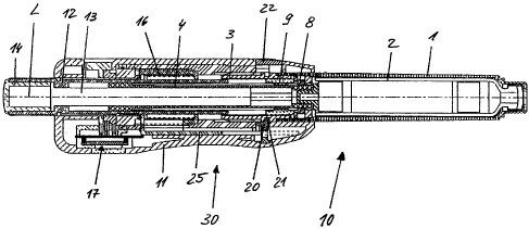
Figure 1 shows a view of a reservoir part 1 and a mechanism holder 3, which
are connected to
each other to form the reservoir module 10 shown in Figure 2.
CA 02451884 2003-12-23
9
Furthermore, in Figures 1 and 2, a piston rod can be seen which protrudes, on
an end of the
mechanism holder 3 facing away from the reservoir part 1, into the mechanism
holder 3 and is
mounted by the mechanism holder 3 such that it can shift in an advancing
direction pointing in
the longitudinal axis L of the piston rod 4, towards a front end of the
reservoir part 1 facing away
from the mechanism holder 3. The reservoir part 1 is substantially a hollow
cylinder which has a
circular cross-section and comprises a connecting region at its front end for
connecting to a
needle holder for an injection needle. The reservoir part 1 serves to
accommodate a reservoir
container which in the example embodiment is formed by an ampoule 2 which can
be seen in the
longitudinal section in Figure 3. An outlet at the front end of the ampoule 2
is sealed fluid-tight
by a membrane. When the needle holder is fastened to the front end of the
reservoir part 1, a rear
portion of the injection needle pierces the membrane, such that a fluid
connection between the
tip of the hollow injection needle and the reservoir 2 is established.
Figure 3 shows the injection apparatus in its entirety, in a longitudinal
section. A piston is
accommodated in the ampoule 2 such that it can shift in the advancing
direction towards the
outlet formed at the front end of the ampoule 2. Shifting the piston in the
advancing direction
displaces product out of the ampoule 2 and delivers it through the outlet and
the injection needle.
The piston is advanced by the piston rod 4 which pushes against the piston via
its front end and
thus moves the piston in the advancing direction when advanced itself. The
piston rod 4 is held
by the mechanism holder 3 such that it can be moved in the advancing direction
once a certain
resistance has been overcome, but not counter to the advancing direction. The
piston rod 4 is
prevented from moving backwards, counter to the advancing direction, by a
blocking means 8.
The blocking means 8 is axially fixed by the mechanism holder 3, i.e. it is
held in the mechanism
holder 3 such that it cannot be moved in and counter to the advancing
direction. It is, however,
mounted by the mechanism holder 3 such that it can be rotated about the
longitudinal axis L. The
blocking means 8 also generates the resistance which has to be overcome in
order to move
forwards.
The blocking means 8 is shown on its own in Figure 6. It is formed by a one-
part annular
element which, rotatable about the longitudinal axis L, abuts the mechanism
holder 3 between
two facing, spaced collars 3b which protrude radially inwards from an inner
surface of the
CA 02451884 2003-12-23
mechanism holder 3. The collars 3b form a fixing means for axially fixing the
blocking means 8.
How the blocking means 8 is mounted in the mechanism holder 3 is most clearly
seen from the
representation of the mechanism holder 3 in Figure 5.
Furthermore, a dosage setting member 9 is accommodated in the mechanism holder
3. The
dosage setting member 9 is formed as a threaded nut and is in threaded
engagement with an outer
thread of the piston rod 4. The dosage setting member 9 is secured against
rotating by the
mechanism holder 3, but is guided such that it can move axially and linearly
in and counter to the
advancing direction. The piston rod 4 and the dosage setting member 9 form a
spindle drive for
selecting the product dosage to be administered.
The ampoule holder 1 and the mechanism holder 3 are connected to each other,
secured against
rotating and shifting, and together form the reservoir module 10 of the
injection apparatus, said
reservoir module 10 comprising the piston rod 4 held by the mechanism holder 3
by means of the
blocking means 8, and the dosage setting member 9. The ampoule holder 1 and
the mechanism
holder 3 together form a front casing section of the injection apparatus. A
rear casing section 11
is connected to said front casing section 1, 3 in a positive lock. The rear
casing section 11 forms
the support for a dosing and activating element 12 and, together with the
dosing and activating
element 12 and parts of a latching means and other parts, forms a dosing and
activating module
30 of the injection apparatus.
Except for the dosage setting member 9, the piston rod 4 and the blocking
means 8, a dosing and
activating device comprises the other components for selecting the product
dosage and activating
the injection apparatus. In particular, it comprises the dosing and activating
element 12. The
dosing and activating device further comprises a counting and indicating means
17 for counting
and optically indicating the selected product dosage. Not least the counting
and indicating means
17 makes the dosing and activating module 30 a high-grade and therefore
expensive part of the
injection apparatus. While the comparatively inexpensive reservoir module 10
is designed as a
disposable module, the dosing and activating module 30 is intended for
repeated use, with
consistently new reservoir modules 10.
CA 02451884 2003-12-23
11
For selecting the product dosage, i.e. for dosing, the dosing and activating
element 12 can be
rotated about the longitudinal axis L and is furthermore mounted by the rear
casing section 11
such that it can linearly shift along the longitudinal axis L, in and counter
to the advancing
direction. The dosing and activating element 12 is hollow cylindrical and
surrounds the piston
rod 4 via a front section. A rear section of the dosing and activating element
12 protrudes out
beyond a rear end of the casing section 11. A rod-shaped dosing slaving means
13 is inserted
into the dosing and activating element 12 from the rear, as far as a collar of
the dosing and
activating element 12 protruding radially inwards. Furthermore, at the rear
end, a closure 14 is
inserted into the dosing and activating element 12, as far as the dosing
slaving means 13. The
dosing slaving means 13 is axially fixed relative to the dosing and activating
element 12 between
the radially protruding collar of the dosing and activating element 12 and the
closure 14. The
dosing slaving means 13 is also connected, secured against rotating, to the
dosing and activating
element 12. For the purpose of dosing, the dosing slaving means 13 protrudes
into the hollow
piston rod 4 from the rear. The piston rod 4 comprises a connecting section 4a
(Figure 4) which
engages with the dosing slaving means 13 such that the piston rod 4 and the
dosing slaving
means 13 and therefore also the dosing and activating element 12 cannot be
rotated relative to
each other about the common longitudinal axis L, but can be moved relative to
each other along
the longitudinal axis L, in and counter to the advancing direction. For this
purpose, the
connecting section 4a is formed as a linear guide for the dosing slaving means
13.
A restoring means 16 elastically tenses the dosing and activating element 12
counter to the
advancing direction, into the initial position shown in Figures 3 and 4. In
the initial position, the
product can be dosed by rotating the dosing and activating element 12 about
the longitudinal axis
L. Then, from the initial position, the selected product dosage can be
delivered by axially
shifting the dosing and activating element 12. The restoring means 16 is
formed by a spiral
spring acting as a pressure spring, which is accommodated in an annular gap
around the dosing
and activating element 12 and axially supported between a collar of the casing
section 11
protruding radially inwards and a collar of the dosing and activating element
12 facing opposite
and protruding radially outwards.
The blocking means 8 fulfils a double function. On the one hand, it ensures
via its blocking
elements 8a that the piston rod 4 cannot be moved back, counter to the
advancing direction,
-- --- ---- - -----
CA 02451884 2003-12-23
12
relative to the mechanism holder 3 and therefore in particular relative to the
piston
accommodated in the ampoule 2. In its double function as a brake, the blocking
means 8
furthermore prevents the piston rod 4 from moving forwards during the dosing
process in which
the dosage setting member 9 is moved axially, counter to the advancing
direction, towards the
dosing and activating element 12.
In the initial position shown in Figures 3 and 4, before dosing, the dosage
setting member 9 abuts
against a delivery stopper 3c (Figure 5) formed by the mechanism holder 3, in
the advancing
direction. The piston rod 4 is in permanent touching contact with the piston.
For the purpose of
dosing, the dosage setting member 9 is moved away from the delivery stopper 3c
towards the
dosing and activating element 12 by the threaded engagement with the piston
rod 4 and the linear
guide from the mechanism holder 3. This reduces a slight distance between a
rear stopper area of
the dosage setting member 9 and a front stopper area of the dosing and
activating element 12, but
on the other hand increases the slight distance between a front stopper area
of the dosage setting
member 9 and the delivery stopper 3c. The latter distance between the delivery
stopper 3c and
the dosage setting member 9 is the path length by which the dosage setting
member 9 and - due
to the threaded engagement - also the piston rod 4 are moved in the advancing
direction in the
course of the delivery movement of the dosing and activating element 12. The
delivery stopper
3c forms a front translational stopper. During the delivery movement, the
piston rod 4 pushes via
its front end, which is formed by a plunger body connected to the piston rod 4
such that it cannot
move in or counter to the advancing direction, against the piston and pushes
the piston forwards
in the advancing direction towards the outlet of the ampoule 2. The
longitudinal axis L forms the
rotational and translational axis of the movements which are performed for the
purpose of dosing
and delivering the product.
The distance which the dosage setting member 9 and the dosing and activating
element 12
exhibit between each other during the dosing process when the dosage setting
member 9 abuts
against the delivery stopper 3c corresponds to the maximum product dosage
which can be
selected and delivered in the course of a delivery. The stroke movement of the
dosing and
activating element 12 is of equal length for each delivery. Dosing merely sets
the distance
between the dosage setting member 9 and the delivery stopper 3c and therefore
the path length
CA 02451884 2003-12-23
13
which can be jointly travelled by the dosing and activating element 12 and the
dosage setting
member 9 in the course of delivery.
The braking function of the blocking means 8 and the braking engagement which
exists between
the piston rod 4 and the blocking means 8 for this purpose are clear from an
overview of Figures
6 and 7. On the one hand, the blocking means 8 comprises two braking elements
8b for the
braking engagement, which are each formed by an elastically flexing catch,
like the blocking
elements 8a before them. In the example embodiment, the blocking means 8 is
formed by a
single annular element from which four elastic catches axially project on an
abutting side. The
catches are arranged in a uniform distribution over the circumference of the
annular element.
Two mutually opposing catches form the blocking elements 8a and the other two
catches,
likewise arranged mutually opposing, form the braking elements 8b.
The piston rod 4 accordingly comprises two returning blocking means 6, which
are formed on
the outer surface on opposing sides and extend in the longitudinal direction
of the piston rod 4,
and two advancing braking means 7, which likewise extend in the longitudinal
direction of the
piston rod 4 on mutually opposing sides. The thread of the piston rod 4 for
the threaded
engagement with the dosage setting member 9 is formed by four remaining
threaded sections 5
which extend over almost the entire length of the piston rod 4. The returning
blocking means 6
and the advancing braking means 7 are each formed by a row of teeth. However,
while the teeth
of the returning blocking means 6 are formed as serrated teeth, narrowing in
the advancing
direction and comprising blocking areas pointing backwards and extending
transverse to the
advancing direction, the two rows of teeth which form the advancing braking
means 7 do not
comprise blocking areas pointing forwards having a comparable blocking effect.
The teeth of the
advancing braking means 7 each exhibit a softer tooth profile as compared to
the returning
blocking means 6. For the braking engagement between the blocking means 8 and
the advancing
braking means 7 of the piston rod 4 is not intended to prevent the piston rod
4 from being
advanced, but merely to make it more difficult, in order to ensure that the
piston rod 4 is not
moved in the advancing direction during dosing. The front sides of the teeth
of the advancing
braking means 7 and the rear sides of the braking elements 8b, which touch the
front sides of the
teeth of the advancing braking means 7, are shaped such that a threshold force
which is not
reached during dosing has to be overcome in order to overcome the braking
engagement. This
CA 02451884 2003-12-23
14
threshold force is larger than the force required to move the teeth of the
returning blocking
means 6 over the blocking elements 8a in the advancing direction. The
threshold force is
preferably at least twice as large as the initial frictional force between the
returning blocking
means 6 and the blocking elements 8a. The frictional force between the latter
also only increases
gradually between two consecutive blocking engagements in the course of the
advancing
movement. The threshold force of the braking engagement, by contrast, has to
be applied from
one blocking engagement to the next, immediately at the beginning of the
advancing movement,
in each blocking engagement. The threshold force should not, however, be so
large that it
distracts the user during delivery.
An undesired advancing movement by the piston rod as a response to the
movement by the
dosage setting member 9 when selecting the dosage can in principle also be
caused by the
blocking engagement of the blocking means 8 alone. However, such a movement is
more reliably
prevented because of the braking engagement than by the blocking engagement
alone.
The connection between the reservoir module 10 and the dosing and activating
module 30 is a
positive lock. On the one hand, a latching engagement exists between the
mechanism holder 3
and the casing section 11 which prevents relative movement in the axial
direction. Beyond the
latching engagement, the front casing section 1, 3 and the rear casing section
11 are guided
axially and linearly directly onto each other, in order to prevent relative
rotating when connected
or connected. The axial guides 3d of the mechanism holder 3, which together
with one or more
corresponding engagement elements of the rear casing section 11 form the
linear guide, can be
clearly seen in Figure 5. The axial guides 3d are formed by guide areas on
guide ribs; they could
also be formed by guide areas in axially extending recesses. In this way,
axial guide channels are
obtained. The guide ribs are axially tapered, such that insertion funnels
leading into the guide
channels are formed for the one or more engagement elements of the rear casing
section 11. In
order to even better centre the casing sections 1, 3 and 11 at the beginning
of connecting, the
guide ribs are also tapered in the radial direction. The one or more
engagement elements of the
rear casing section 11 is or are preferably formed like the axial sections 3d
on the surface counter
area, i.e. the inner surface area, of the rear casing section 11.
CA 02451884 2003-12-23
The latching engagement exists between a first, female latching element 3a of
the mechanism
holder 3 (Figure 5) and a latching ring 20 which is connected to the rear
casing section 11 such
that it can move radially but not axially. The latching ring 20 forms a
second, male latching
element 21 which radially engages directly with the first latching element 3a.
A lock/latch
connection exists between the first latching element 3a and the second
latching element 21 which
prevents the reservoir module 10 and the dosing and activating module 30 from
moving axially
relative to each other.
Figures 3 and 4 show the latching element 21 in latching engagement with the
latching element
3a. The latching element 3a is formed by an annular stay and a groove which
runs around the
outer surface of the mechanism holder 3. The annular stay forms a rear side
wall of the groove.
The second latching element 21 is formed by a cam which protrudes radially
inwards from the
inner surface of the latching ring 20 and which in the latching engagement is
pushed radially
inwards over an inner surface area of the rear casing section 11, protruding
into the
accommodating latching element 3a, by a restoring means 24. The latching ring
20 is supported
in its entirety in the radial direction on an inner surface area formed by the
rear casing section 11,
by means of the restoring means 24, such that the restoring means 24 pushes
against the outer
surface of the latching ring 20 roughly in a radial extension of the latching
element 21. The
latching ring 20 surrounds the mechanism holder 3 and can be moved in its
entirety radially back
and forth against the restoring force of the restoring means 24, such that the
second latching
element 21 can be moved in and out of latching engagement with the first
latching element 3a.
The rear casing section 11 forms a tight sliding guide for the radial movement
of the latching ring
20. On its side radially opposite the latching element 21, the latching ring
20 forms an unlatching
button 22 for the user. In order to radially guide the restoring means 24
formed as a pressure
spring, a guide cam projects radially from the outer surface area of the
latching ring 20 facing
away from the latching element 21.
Two blocking cams 23, which press radially outwards against a latching block
25, furthermore
project from the outer surface area of the latching ring 20, in the
circumferential direction on both
sides of said guide cam and axially behind the guide cam. Since the blocking
cams 23 abut
against the latching block 25, a radial movement of the latching element 21 -
which could result
in the latching engagement being released - is prevented. The latching
engagement between the
CA 02451884 2003-12-23
16
latching elements 3a and 21 is thus secured by the latching block 25. The
latching engagement is
secured in every position of the dosing and activating element 12, except for
a releasing position
which the dosing and activating element 12 assumes at the end of its delivery
movement. The
releasing position therefore coincides with the foremost shifting position
which the dosing and
activating element 12 assumes when it abuts the dosage setting member 9 in the
course of its
delivery movement and the dosage setting member 9 for its part abuts against
the delivery stopper
3c of the mechanism holder 3. Providing the dosing and activating module 30 is
not yet
connected to the reservoir module, a mechanical stopper for the dosing and
activating element 12
is formed by a stopper element 31 of the dosing and activating device. In the
example
embodiment, a reset holder ring which serves to reset the indicator 17 forms
the stopper element
31. The dosing and activating element 12 abutting against said stopper element
31 defines the
releasing position of the dosing and activating element 12 in this case, the
releasing position
defined by the stopper element 31 corresponding to that defined by the dosage
setting member 9
abutting the delivery stopper 3c.
Figure 8 shows the latching block 25. In the example embodiment, it is formed
as one piece by a
blocking slider. The latching block 25 comprises a plate-shaped main body
which extends axially
when assembled, as for example shown in Figure 4. At one end, a stay 26
projects at right angles
from the main body. When assembled, the stay 26 extends radially as far as the
dosing and
activating element 12. The stay 26 serves to fasten the latching block 25 to
the dosing and
activating element 12 which for this purpose comprises two annular stays
formed axially spaced
on an outer surface area, which form the slaving means 15a and 15b. The front
slaving means 15a
simultaneously forms the support collar for the restoring means 16. In the
annular space formed
between the slaving means 15a and 15b, the latching block 25 protrudes in via
its stay 26 and is
tightly enclosed axially on both sides by the two slaving means 15a and 15b.
At a front end facing away from the stay 26, the main body of the latching
block 25 is provided
with an axial recess 27 which is open towards the front end of the latching
block 25. In this way,
blocking tongues 28 extending axially on both sides of the recess 27 are
formed. The blocking
cams 23 of the latching ring 20 are arranged such that each of said blocking
cams 23 pushes
against one of the blocking tongues 28, providing the dosing and activating
element 12 does not
CA 02451884 2003-12-23
17
assume the releasing position. When the latching block 25 moves axially, the
restoring means 24
for the latching element 21 extends through the axial recess 27.
Indentation recesses 29 are furthermore formed in the main body of the
latching block 25, and
define the releasing position of the dosing and activating element 12. One
indentation recess 29 is
provided for each of the blocking cams 23. The position of the indentation
recesses 29 is selected
such that they only overlap the blocking cams 23, and thus allow the blocking
cams 23 to be
inserted, when the dosing and activating element 12 has been advanced into its
releasing position.
It is clear that in the arrangement specifically selected in the example
embodiment, a single
blocking cam 23 could also be provided and the latching block 25 accordingly
comprise only one
indentation recess 29 and possibly also only one blocking tongue 28.
Furthermore, the latching
block could in principle be produced together with the dosing and activating
element 12 as one
piece. Forming it as a separate part, however, offers advantages with regard
to production,
assembly and the dosing and activating element 12 co-operating with the piston
rod 4. With
respect to the installation length of the latching block 25, it should also be
pointed out that the
latching block 25 is supported, on its outer side facing away from the
latching element 21, on an
inner surface area of the casing 11. In this way, the stability of securing
the latching engagement
is increased. The casing 11 preferably forms an axial guide for the latching
block 25.
The functionality of the injection apparatus is described in the following,
wherein it is assumed
that a new reservoir module 10 and a dosing and activating module 30 which has
already been
used at least once are assembled and a product is then delivered for the first
time.
The dosing and activating module 30 and the new reservoir module 10 are
aligned axially with
respect to each other, such that their two longitudinal axes are flush with
each other. The
reservoir module 10 is then inserted via its rear end into the casing 11,
which is open to the front,
of the dosing and activating module 30.
This centres the casing section 1, 3 and the casing section 11 on the tapered
ends of the guide ribs
3d of the mechanism holder 3. While being slid on, the two casing sections are
guided axially and
linearly onto each other in a rotational angular position pre-set by the
linear guide, until the
CA 02451884 2003-12-23
18
casing sections 1, 3 and 11 assume a connecting end position in which the
latching engagement
of the latching elements 3a and 21 can be established or can be set by itself.
The dosing and activating element 12 is locked in pre-set rotational angular
positions relative to
the rear casing section 11. The linear guide of the casing sections 1, 3 and
11 and the rotational
angular locking positions of the dosing and activating element 12 are adjusted
to each other such
that the engagement, secured against rotating, between the dosing and
activating element 12 and
the piston rod 4 is established in every locking position of the dosing and
activating element 12
and every rotational angular position in which the casing sections 1, 3 and 11
are linearly guided
onto each other.
If the dosing and activating element 12 is situated in an axial position
relative to the casing
section 11 which is behind the releasing position, the latching element 21 is
held in its radially
innermost position by the latching block 25. In this position of the latching
element 21, the
dosing and activating module 30 and the reservoir module 10 cannot be slid
onto each other up to
the connecting end position and therefore also cannot be connected to each
other, since the
annular stay formed on the outer surface of the mechanism holder 3, which
forms a part of the
first latching element 3a, comes to rest abutting against the second latching
element 21 first.
The annular stay can be reduced to a short radial protrusion in the tangential
direction, if it is
ensured that the casing sections 1, 3 and 11 can only be assembled in the
rotational angular
position in which such a protrusion and the second latching element 21 come to
rest in an axial
flush. The annular stay or radial protrusion could also form the first
latching element 3a alone,
since the essential function of the first latching element 3a is to allow the
connection between the
reservoir module 10 and the dosing and activating module 30 to be established
only when the
dosing and activating element 12 assumes its releasing position. If this
condition is fulfilled, then
the dosing and activating element 12 would ensure, when the connection between
the reservoir
module 10 and the dosing and activating module 30 is established, that the
dosage setting
member 9 is situated in its dosing zero position in which it abuts the
delivery stopper 3c of the
mechanism holder 3.
CA 02451884 2003-12-23
19
In order to fulfil the condition described above, the user pushes the dosing
and activating element
12 axially forwards relative to the rear casing section 11 as far as the
releasing position. In this
relative position between the rear casing section 11 and the dosing and
activating element 12, the
blocking cams 23 can be moved into the indentation recesses 29 of the latching
block 25. The
user therefore not only pushes the dosing and activating element 12 at least
as far as the releasing
position, but simultaneously also pushes the first latching element 20 out of
latching engagement
by means of the unlatching button 22. The reservoir module 10 can then be
moved axially over
the annular stay of the first latching element 3a and inserted further into
the rear casing section
11. The user can let go of the unlatching button 22. As soon as the first
latching element 21
overlaps the second latching element 3a, it snaps into the accommodating
latching element 3a due
to the force of the restoring means 24, such that the latching engagement is
established. The
reservoir module 10 and the dosing and activating module 30 are then connected
to each other in
a defined way with respect to the position of the dosage setting member 9 and
the piston rod 4. If
the dosage setting member 9 still exhibited a slight distance from the
delivery stopper 3c before
the latching engagement is established, this distance is eliminated due to the
action of the dosing
and activating element 12, required to establish the connection. A resultant
delivery of product
can be accepted and even desired, for the purpose of priming the injection
needle. This preferably
resets the counting and indicating means 17 to zero.
In the defined initial state brought about in this way, the user can dose the
product. The product is
dosed by rotating the dosing and activating element 12 about the longitudinal
axis L and relative
to the casing section 11. Since the dosing slaving means 13 is connected to
the dosing and
activating element 12, secured against rotating, and for its part engages with
the piston rod 4,
secured against rotating, the dosing and activating element 12 slaves the
piston rod 4 during its
rotational dosing movement. Due to the threaded engagement between the piston
rod 4 and the
dosage setting member 9 and the linear guide of the dosage setting member 9 by
the mechanism
holder 3, the dosage setting member 9 performs an axial, translational dosing
movement, pre-set
by the thread pitch of the reciprocal threaded engagement, towards the dosing
and activating
element 12. The dosing and activating element 12 forms a rear translational
stopper 12c which
limits the translational dosing movement of the dosage setting member 9 and
thus defines the
maximum delivery stroke which may be set.
CA 02451884 2003-12-23
The counting and indicating means 17 counts the dosage units corresponding to
the rotational
angular position of the dosing and activating element 12 and indicates it
optically.
Once the desired product dosage has been selected, the dosing process is
completed. The selected
product dosage is delivered by means of the delivery movement, pointing in the
advancing
direction of the piston, of the dosing and activating element 12. In the
course of its delivery
movement, the dosing and activating element 12 abuts against the dosage
setting member 9 and
slaves it. When the dosage setting member 9 abuts against the delivery stopper
3c of the
mechanism holder 3 in the course of the delivery movement, the delivery
movements of the
dosing and activating element 12 and the delivery of product are completed.
Once the user lets go
of the dosing and activating element 12, it is preferably moved counter to the
advancing
direction, back into a new initial position for dosing and delivering the
product again, by the
restoring means 16. The counting and indicating means 17 is preferably coupled
to the dosing
and activating element 12 such that it has in the meantime been reset back to
zero. It possibly
possesses means for counting and indicating the total product amount already
delivered and thus
the residue product amount remaining in the ampoule 2.
In order to detach the reservoir module 10 from the dosing and activating
module 30, the dosing
and activating element 12 is advanced as far as the releasing position, i.e.
until it abuts against the
dosage setting member 9. in this position, the user can release the latching
engagement again by
pushing onto the unlatching button 22, and separate the reservoir module 10
from the dosing and
activating module 30.
Figures 9 to 13 shows a longitudinal section and four cross-sections of a
second example
embodiment of an injection apparatus. The injection apparatus of the second
example
embodiment is identical to that of the first example embodiment with respect
to the latch and
latching block 25, such that reference is made in this regard to the
description of the first example
embodiment. In particular, the latching block 25 of the second example
embodiment is identical
to that of the first example embodiment with respect to all its functional
details. The same applies
to the latching elements 3 a and 21.
CA 02451884 2003-12-23
21
The latching ring 20 and the position of the blocking cams 23 relative to the
latching element 21
and relative to the latching block 25 in the initial state of the apparatus
can be seen particularly
clearly in the cross-sections of Figures 10, 11 and 12, to which reference is
made in this regard,
also as representative for the first example embodiment.
The injection apparatus of the second example embodiment differs from the
first example
embodiment in the engagement and the progression of movement of the components
involved in
dosing. Furthermore, the mechanism holder fulfils, in addition to the
functions of the mechanism
holder of the first example embodiment, in particular the function of
positioning the dosage
setting member in discrete rotational angular positions which may be changed
relative to the
mechanism holder, for the purpose of dosing. The blocking means of the second
example
embodiment, by contrast, is embodied more simply than that of the first
example embodiment.
Primarily, only the differences as compared to the first example embodiment
will be described in
the following, wherein for components which are identical in their basic
function to the
components of the same name in the first example embodiment but differ in
details, numbers in
the thirties with the same end digit, or exactly the same reference numerals
as in the first example
embodiment, as used. Where no statements are made regarding the second example
embodiment,
the corresponding statements regarding the first example embodiment shall
apply.
In the second example embodiment, the dosing and activating element 32, which
can be axially
and linearly moved relative to the rear casing section 11 and rotated about
the longitudinal axis L,
is connected to the dosage setting member 39, secured against rotating. The
dosing and activating
element 32 and the dosage setting member 39 can be moved in and counter to the
advancing
direction, relative to each other and relative to casing sections 1, 3 and 11.
The piston rod 4 is
held by a mechanism holder 3, secured against rotating. In co-operation with
blocking elements
of the blocking means 38, formed on the mechanism holder 3 as one piece, the
returning blocking
means 6, which is functionally identical to the first example embodiment,
prevents the piston rod
4 from moving counter to the advancing direction, but allows it to move in the
advancing
direction. The blocking elements simultaneously form the returning block and
the rotational
block for the piston rod 4. Furthermore, as previously in the first example
embodiment, the
dosing and activating element 32 forms a sliding guide for the piston rod 4.
CA 02451884 2003-12-23
22
During dosing, the dosing and activating element 32 performs the same
rotational dosing
movement as the dosing and activating element 12 of the first example
embodiment. However,
since the engagement is secured against rotating, the dosage setting member 39
is slaved during
the rotational dosing movement. The threaded engagement between the piston rod
4 and the
dosage setting member 39 is again comparable to that of the first example
embodiment, such that
due to the rotational dosing movement and the threaded engagement with the
piston rod 4, a
stopper 39c formed by the dosage setting member 39 is moved, in the course of
dosing, counter
to the advancing direction, towards a front end of the dosing and activating
element 32. As
opposed to the first example embodiment, the dosage setting member 39 thus
completes a
rotational dosing movement and a translational dosing movement relative to the
front casing
section during dosing, while the piston rod 4 remains stationary. Once dosing
has been
completed, the delivery movement of the dosing and activating element 32
advances the piston
rod 4 by the path length which corresponds to the slight distance between a
stopper area of the
dosage setting member 39 and the delivery stopper 3c of the mechanism holder
3, set by the
dosing.
The translational dosing movement of the dosage setting member 39 is limited
counter to the
advancing direction by a rear translational stopper 11 c which is formed
directly by the rear casing
section 11 itself. In the second example embodiment, too, the rotational and
translational axis of
the components involved in dosing and delivering the product forms the
longitudinal axis L.
As in the first example embodiment, the front casing section 1, 3 forms a
sliding guide for the
dosage setting member 39. In order to form the sliding guide, an inner surface
area of the
mechanism holder 3 and an outer surface area of the dosage setting member 39
are in sliding
contact with each other. The dosing and activating element 32 engages with an
inner surface area
of the dosage setting member 39, to form the connection, secured against
rotating, between the
dosage setting member 39 and the dosing and activating element 32.
In the second example embodiment, the piston rod 4 comprises no braking means
of its own
beyond the returning blocking means 6. Rather, the front sides of the serrated
teeth of the
returning blocking means 6 also form the braking means on their own. The
piston rod 4 of the
second example embodiment can, however, be replaced by the piston rod 4 of the
first example
CA 02451884 2003-12-23
23
embodiment. Accordingly, the mechanism holder 3 of the second example
embodiment would in
this case also have to form at least one braking element, preferably both
braking elements, of the
first example embodiment.
Figures 14 to 16 show the mechanism holder 3 of the second example embodiment
in a
perspective representation, a side view and in the cross-section A-A indicated
in the side view.
As in the first example embodiment, the mechanism holder 3 is embodied as a
one-part sleeve
part, preferably as a plastic injection moulded part. It comprises a bulge 3e
on the outer surface of
a front sleeve section. The front sleeve section is plugged into the reservoir
part 1 and locked
non-detachably, at least for the user, to the reservoir part 1 by means of the
bulge 3e.
The latching element 3a is formed on a middle sleeve section of the mechanism
holder 3, as in
the first example embodiment.
A rear sleeve section, connected to the latching element 3a, forms a plurality
of axial guides 3d
on its outer circumference. The axial guides 3d are formed by guide ribs which
protrude radially
on the outer circumference of the rear sleeve section. More precisely, the
axial guide formed by
the axially extending, straight side walls of said guide ribs, such that - as
in the first example
embodiment - axial guiding channels are obtained. The guide ribs protrude out
from the middle
sleeve section like fingers, as far as the rear end of the mechanism holder 3,
where they taper off
axially. The axial guide 3d serves to linearly guide the rear casing section
11 when the reservoir
module 10 is connected to the dosing and activating module 30. As can be seen
in Figure 9 and
most clearly in Figure 11, engagement elements lld project radially inwards
from the inner
surface area of the rear casing section 11, corresponding in number and
adapted in shape. One
engagement element I ld protrudes into each of the axial guides 3d and is
linearly guided by the
axial guide 3d when the front casing section 1, 3 and the rear casing section
1 I are slid into each
other in order to be connected. In this way, it is ensured that there is no
relative rotating between
the front casing section 1, 3 and the rear casing section 11 when the
engagement, secured against
rotating, between the dosing and activating element 32 and the dosage setting
member 39 is
established in the course of connecting.
CA 02451884 2003-12-23
24
Since the guide ribs taper off axially at their rear ends, and the guide
channels are thus widened
into insertion funnels, centring between the front casing section 1, 3 and the
rear casing section
11, for the purpose of connecting, is made easier. The guide ribs also taper
off at their ends
radially with respect to the surface area of the mechanism holder 3, which
makes centring the
casing sections 1, 3 and 11 into a rotational angular position pre-set by the
axial guide 3d, relative
to each other, even easier.
Just as the front casing section 1, 3 and the rear casing section 11 are
prevented from rotating
relative to each other when sliding them into each other, the dosage setting
member 39 is also
fixed with respect to its rotational angular position relative to the front
casing section 1, 3, the
dosage setting member 39 being detachably fixed in order to allow the
rotational movement of
the dosage setting member 39 necessary for dosing. In order therefore to
enable the dosing
movement of the dosage setting member 39 on the one hand, but to prevent an
undesired dosing
movement by establishing the connection between the front casing section 1, 3
and the rear
casing section 11, the dosage setting member 39 is fixed by the mechanism
holder 3 in discrete
rotational angular positions, by means of a releasable locking connection.
Figures 17 to 20 show individual representations of the dosage setting member
39. For forming
the locking connection, a number of locking recesses 39g are formed on the
outer surface area of
the dosage setting member 39, distributed in regular separation over the
circumference. Each of
the locking recesses 39g is formed by a straight, axially extending furrow
having a rounded
contour running in its cross-section.
The mechanism holder 3 is provided with two locking projections 3g (Figures 15
and 16). The
two locking projections 3g project radially inwards from an inner surface area
of the mechanism
holder 3 in the rear sleeve section of the mechanism holder 3. They are
arranged diametrically
opposed to each other. The respective surface region of the mechanism holder
3, on which one of
the locking projections 3g is formed, forms a spring element 3f which is
elastically flexible in the
radially direction. Due to the elastic flexibility and the rounded shape of
the locking projections
3g, in conjunction with the rounded profile of the locking recesses 39g, the
locking engagement
between the locking projections 3g and the opposing locking recesses 39g may
be released. This
is necessary for selecting the dosage. On the other hand, the locking
engagement is however
CA 02451884 2003-12-23
designed such that the dosage setting member 39 is rotationally angularly
fixed sufficiently stable
that there cannot be any undesired dosing movement of the dosage setting
member 39 when the
front casing section 1, 3 and the rear casing section 11 are connected, when
the rotational
coupling between the dosing and activating element 32 and the dosing and
activating element 32
is established. The locking connection between the mechanism holder 3 and the
dosage setting
member 39 has the advantageous side effect of a tactile signal during dosing.
In order to maintain
the favourable elasticity of the spring element 3f, the rear sleeve section of
the mechanism holder
3 is cut away in the surface region in question, such that the spring element
3f is maintained as an
annular segment extending in the circumferential direction which is axially
free on both sides.
Axial guides 39d for the engagement, secured against rotating, between the
dosage setting
member 39 and the dosing and activating element 32 may likewise be seen in
Figures 17, 18 and
20. The dosing and activating element 32 is provided with at least one
engagement element, in
order to obtain the axial linear guide, i.e. the rotational block, between the
dosing and activating
element 32 and the dosage setting member 39. The axial guides 39d are again
guide channels
formed by a number of guide ribs extending axially in a straight line. Each of
the guide ribs
tapers off axially and radially at its rear end facing the dosing and
activating element 32, in order
to make centring between the dosing and activating element 32 and the dosage
setting member 39
easier, when the engagement, secured against rotating, is established. The
same design is
therefore used for the axial linear guide of the dosage setting member 39 and
the dosing and
activating element 32 as for the axial linear guide of the casing sections 1,
3 and 11.
For the sake of completeness, reference is lastly also made to the dosing
thread 39a and the
delivery stopper 39c of the dosage setting member 39, which can most clearly
be seen in Figure
18.
Lastly, two rotational blocks are provided for the dosage setting member 39
which are active in
the two axial end positions of the dosage setting member 39. Reference is
additionally made in
this regard to Figure 22.
In order to prevent the possibility of the piston rod 4 being moved back in
response to a rotational
dosing movement by the dosage setting member 39, rotational stoppers 39h are
formed at a front
CA 02451884 2003-12-23
26
end of the dosage setting member 39. In the front position, which the dosage
setting member 39
assumes directly after the product is delivered or before the dosage is
selected, the rotational
stoppers 39h engage with rotational counter stoppers 3h formed on the
mechanism holder 3
(Figure 16). The rotational stoppers 39h axially project from a front abutting
side of the dosage
setting member 39, and the rotational counter stoppers 3h protrude from an
axially facing
abutting area of the mechanism holder 3 forming the delivery stopper 3c,
axially opposed to the
rotational stoppers 39h. The engagement between the rotational stoppers 39h
and the rotational
counter stoppers 3h is such that it allows a rotational dosing movement in a
rotational direction,
which causes a translational dosing movement of the dosage setting member 39
directed away
from the delivery stopper 3c, but prevents a rotational dosing movement in the
opposite rotational
direction, in the front axial end position.
Furthermore, another pair of rotational stoppers and rotational counter
stoppers is provided,
which are formed and co-operate in basically the same way as the stoppers 3h
and 39h. Said
second pair of rotational stoppers are rotational stoppers 39i on the one
hand, which axially
project from a rear abutting area of the dosage setting member 39, and
rotational counter stoppers
11 i on the other, which axially protrude from the facing stopper abutting
area of the rear
translational stopper t lc towards the dosage setting member 39, which however
cannot be seen
in Figure 9 due to their small dimensions. In the rear end position, the rear
pair of rotational
stoppers lli/39i prevents the possibility of the piston rod 4 being moved in
the advancing
direction in response to a dosing movement by the dosage setting member 39,
directed against the
rear translational stopper 11 c.
The height, i.e. the axial length, of all the rotational stoppers 3h, 39h, l
li and 39i is adjusted to
the thread pitch of the engaged dosing thread of the piston rod 4 and the
dosage setting member
39. The rotational stoppers are axially sufficiently short that the rotational
dosing movement
which moves the dosage setting member 39 away from the respective
translational stopper 3c or
11 c is not impeded.
When assembling the components of the reservoir module 10, the dosage setting
member 39 is
screwed onto the piston rod 4 as far as a pre-set axial position, as may be
seen from Figure 9. The
piston rod 4, together with the screwed-on dosage setting member 39, is then
inserted into the
CA 02451884 2003-12-23
27
mechanism holder 3 from behind, until its blocking means 38 comes into
blocking engagement
with the returning blocking means 6 of the piston rod 4 and furthermore the
engagement, secured
against rotating, between the rotational stoppers 39h of the dosage setting
member 39 and
rotational counter stoppers of the mechanism holder 3 is established. Even
while being inserted
into the mechanism holder 3, the dosage setting member 39 is axially and
linearly guided by the
mechanism holder 3 via the locking engagement between the locking projections
3g and the
locking recesses 39g, until the dosage setting member 39 abuts the delivery
stopper 3c of the
mechanism holder 3. In this front end position of the dosage setting member 39
relative to the
mechanism holder 3, the engagement, secured against rotating, between the
rotational stoppers 3h
and 39h has also already been established.
In this state, the mechanism holder 3 and a reservoir part 1, already fitted
with a reservoir, are
connected to each other.
In a following step, the rear casing section 11 of the completely assembled
dosing and activating
module 30 is slid onto the mechanism holder 3, wherein the mechanism holder 3
and the rear
casing section 11 can be centred with respect to each other due to the axial
guides 3d and the
engagement elements 11 d of the rear casing section 11 and, once centred, are
axially and linearly
guided onto each other due to the guide engagement. In the course of sliding
the rear casing
section 11 onto the mechanism holder 3, the dosing and activating element 32
comes into
engagement, secured against rotating, with the dosage setting member 39,
wherein here too a
certain centring is also possible first, using a linear guide corresponding to
the axial guides 3d
and the engagement elements 11 d.
The dosing and activating element 32 is in locking engagement with the rear
casing section in
discrete rotational angular locking positions and in the locking engagement,
i.e. in the respective
rotational angular locking position, is axially and linearly guided. The
rotational angular
difference between two consecutive rotational angular locking positions
corresponds to one
dosage unit. The linear guide between the mechanism holder 3 and the rear
casing section 11 on
the one hand, and the discrete rotational angular positions of the dosage
setting member 39
relative to the mechanism holder 3 (locking projections 3g and locking
recesses 39g) and the
rotational angular locking positions of the dosing and activating element 32
relative to the rear
CA 02451884 2003-12-23
28
casing section 11 on the other, are adjusted to each other such that the two
casing sections 1, 3
and 11 are always slid linearly over each other in a rotational angular
position such that the
dosage setting member 39 and the dosing and activating element 32 are also
aligned relative to
each other for their engagement, secured against rotating, such that there is
no relative rotating
between the components involved in dosing while the reservoir module 10 is
connected to the
dosing and activating module 30.
With respect to the other details of assembling, in particular of establishing
the latching
engagement, and of the functionality of the injection apparatus in accordance
with the second
example embodiment, reference is made to the description of first example
embodiment.
Rotational blocks can also be provided in the injection apparatus in
accordance with the first
example embodiment, which prevent undesired response movements by the piston
rod 4 in the
two axial end positions of the dosage setting member 9 of the first example
embodiment. Figure
21 shows the two rotational blocks, which are formed in the same way as the
rotational blocks of
the second example embodiment. However, the rotational counter stoppers which
in the second
example embodiment are formed on the casing sections 1, 3 and 11 are formed in
the first
example embodiment by the blocking means 8 on the one hand and the dosing and
activating
element 12 on the other. Thus, a number of rotational stoppers 8h are formed
on the abutting side
of the blocking means 8 axially facing the dosage setting member 9 and axially
protrude towards
the dosage setting member 9. Since the blocking means 8 is axially and
immovably mounted by
the front casing section 1, 3 and connected, secured against rotating, to the
piston rod 4, a
rotational block for the rotational dosing movement between the piston rod 4
and the dosage
setting member 9 is also obtained, via the front pair of rotational stoppers
8h/9h. The second pair
of rotational stoppers is formed between the dosage setting member 9 and the
rear translational
stopper 12c. As in the second example embodiment, a number of rotational
stoppers 12i protrude
axially towards the dosage setting member 9 from the abutting area of the
translational stopper
12c axially facing the dosage setting member 9. As in the second example
embodiment, the
dosage setting member 9 is provided on its rear side with rotational stoppers
9i which in the rear
axial end position of the dosage setting member 9 engage with the rotational
stoppers 12i. In the
rear axial end position of the dosage setting member 9, the rear pair of
rotational stoppers 9i/12i
CA 02451884 2003-12-23
29
only allows the rotational dosing movement which causes a translational dosing
movement of the
dosage setting member 9 in the advancing direction.
Reference numerals:
1 reservoir part, ampoule holder
2 reservoir, ampoule
3 mechanism holder
3a first latching element
3b fixing means
3c delivery stopper, translational stopper
3d axial guide
3e bulge
3f spring element
3g locking projection
3h rotational stopper
4 piston rod
4a connecting section
threaded section
6 returning blocking means, row of teeth
7 advancing braking means, row of teeth
8 blocking means 8
8a blocking element
8b braking element
8h rotational stopper
9 dosage setting member
9h rotational stopper
9i rotational stopper
reservoir module
11 rear casing section
11 d engagement element
11 i rotational stopper
CA 02451884 2003-12-23
12 dosing and activating element
12i rotational stopper
13 dosing slaving means
14 closure
15a slaving means, annular stay
15b slaving means, annular stay
16 restoring means
17 counting and indicating means
18 -
19 -
20 latching ring
21 second latching element
22 unlatching button
23 blocking cam
24 restoring means
25 latching block
26 slaving means, stay
27 axial recess
28 blocking tongue
29 indentation recess
30 dosing and activating module
31 stopper element
32 dosing and activating element
33 - 37 -
38 blocking means
39 dosage setting member
39a dosing thread
39c delivery stopper
39d axial guide
39g locking recess, axial guide
39h rotational stopper
39i rotational stopper