Note: Descriptions are shown in the official language in which they were submitted.
CA 02451958 2003-12-17
WO 03/007776 PCT/GB02/03309
SURFACE CLEANING APPARATUS
This invention relates to a surface cleaning apparatus,
such as for a floor or upholstery, incorporating an
elongate rotatable brush arrangement and an electric motor
for rotating the brush.
Current surface cleaning apparatus generally employs
suction means. One of the drawbacks of such suction means
is that the fans used to generate suction are relatively
inefficient, i.e. typically 10 to 12 percent efficient in
use, with the result that such apparatus tends not to be
easily portable. This is especially the case where the
apparatus incorporates batteries for powering the motor.
It is therefore not practical to incorporate batteries of
sufficient power in a readily portable suction cleaner in
order to provide the degree of suction required for
effective cleaning.
It is known to provide surface cleaning apparatus, such as
for sweeping, in which an elongate brush arrangement,
sometimes known as a brush bar, is supported for rotation
in a housing which is adapted to be propelled at least in
a forwards direction. The brush arrangement generally
extends transversely of the housing and is adapted to
contact a surface beneath it. The brush arrangement is
arranged to be rotated by friction resulting from
propelling the housing across a floor. The housing can be
provided with wheels which contact the surface. One of the
drawbacks of such a construction is that the friction drive
is not very effective.
It is also known to provide one or more auxiliary brush
arrangements extending outwardly from one or two front
corners of the housing. The auxiliary brush arrangement is
CA 02451958 2003-12-18
2- 31 f~~~~;!'C.'J EGQ:'/'r~02J.~ C 02 033j'
- 2 - provided for rotation about an axis inclined to the
vertical and is provided with radial bristl,es. An
auxiliary brush arrangement of this kind is described in
GB-A-1 547-286. The auxiliary brush arrangement is freely
rotatable and relies for its rotation on contact with the
floor or a skirting board of 'a room during propulsion of
the apparatus-across the floor. Such means of rotation is
unreliable and results in particles of dust and/-or dirt on
the floor being flicked towards the elongate rotating brush
assembly for collection by the apparatus. Furthermore,
contact of the circular auxiliary brush arrangement with
the floor or a skirting board results in bristles of the
auxiliary brush arrangement which extend outwardly sideways
from the housing undergoing angular rotation effectively in
a backwards direction. This means that an auxiliary brush
means extending outwardly from a front right hand corner of
the housing, as viewed from above and behind the apparatus,
would be rotated in a clockwise direction and would flick
dust and or dirt around behind it in the direction of the
elongate rotating brush arrangement. This is not very
satisfactory.
GB-A-1 442 587 describes a domestic sweeper for floor
coverings comprising a casing, a handle, a cylindrical
brush, an electric motor connected to the brush to effect
rotation of the brush, and a dust collector located between
the brush and the motor.
US-A-3 184 775 describes an electric carpet sweeper
comprising a hollow body, a dirt receiving compartment, a
rotatable brush, an electric motor connected to drive the
brush, a rechargeable electric battery within the body for
supplying current to the motor, and conduit means for
conmecting the compartment to an electric vacuum,cl.eaner.
AMENDED SHFET 12-0-2-2003
CA 02451958 2003-12-18
r' ...r G r=~ r.,., : o ~=,'q-.....i .~fy I_ ~ ~it -1=~,~'~ f[~ r) r'r7 Q
f II~1L':1;. ,_..'L~G. ._V...._ , ..!!_~-/t i~~~IL: ..~0..~'-"~L/:' . I ' ~V I
'n'L..' ~J~. ~JaJ~J
- 3 -
It is therefore an object of the present invention to
provide a surface cleaning apparatus which overcomes, or at
least ameliorates, at least some of the problems of known
~ .
apparatus.
According to a first aspect of the present invention there
is provided a surface cleaning apparatus comprising:
a body comprising a rear compartment, a forward-compartment
and an intermediate compartment arranged between the rear
and forward compartments;
an elongate rotatable brush arrangement positioned within
and extending across the forward-compartment;
an electric motor positioned in the rear compartment;
drive means extending between the rotatable brush
arrangement and the electric motor; and
elongate handle means (33; 154),
wherein the handle means (33; 154) is rotatable about an
axial direction thereof relative to the body and is
pivotable about an axis transverse to the axial direction
thereof to facilitate steering of the apparatus.
A battery, such as a rechargeable battery, may be,
positioned in the rear -compartment t=ogether with the
electric motor. Alternatively, the electric motor may be
mains powered.
The rotatable brush arrangement may extend substantially
the entire width of~the forward compartment.
AMENDED SH=EET 12 02-2003
CA 02451958 2003-12-18
n D~~ 02749029.1 ~r'
} 1~' 5'~~C.'r~in,
: ~ ~._.~~=Ji Til~ 1~ . . ' 1 ~J~
- 4 -
The intermediate compartment may be provided with a
removable closure, such as a removable side wall, for the
removal of debris therefrom.
The drive means may pass at least partly through the
intermediate compartment. The drive means may pass through
a tunnel which passes at least partly through the
intermediate compartment. The drive means may be
positioned adjacent one side of the intermediate
compartment.
The drive means may comprise a belt, for example a toothed
belt, drive.
A wall may be provided between the rear compartment and the
inte'rmediate compartment to seal the rear compartment from
the intermediate compartment.
A wall may be provided between the intermediate compartment
and the forward compartment, the wall extending from the
base of the intermediate compartment and terminating short
of the top thereof. The top of the wall may be at
substantially the same height as the top of the brush
arrangement. The wall may be inclined rearwardly. The
angle of inclination may be in the range of 15 to 20
degrees, for example.
The length of the handle means may be varied. For example,
the handle means may be interchangeable. Thus, one handle
-30 means may be relatively short and another,handle means may
be relatively long. Alternatively, the other handle means
may serve to extend the one handle means.
An auxiliary brush arrangement may be provided at one side
of the body of the apparatus. The auxiliary brush
AMENDED SHEET Q-02-20.O1~)
CA 02451958 2003-12-18
õ
-.'.f nr. =~D ilw l.? ~~ 1J
. i.~
~~ "~~ ~~~~~1-k ~ - 2 ~J
~-~ .i
f"I i
~' :! 2 l/ '..., ld~~.~
- 5 -
arrangement may extend outwardly from the forward
compartment. The auxiliary brush arrangement may rotate
about an axis inclined to the vertical. The auxiliary
brush arrangement may be provided with radial bristles.
The radial bristles may be inclined at an acute angle to
the axis of rotation of the auxiliary brush arrangement.
The auxiliary brush arrangement may be driven by the
electric motor or by friction.
The forward compartment includes in the lower face thereof
an aperture through which bristles of the brush arrangement
protrude. A front part of the forward compartment may be
movable to expose bristles at the front of the apparatus.
For example, the cover may be removable or may be
pivotable,'or otherwise movable, to expose bristles at the
front of the apparatus. -
The rear compartment may be provided with ground-engaging
wheels.
According to a second aspect of the present invention there
is provided a surface cleaning apparatus comprising a body
provided with an elongate rotatable brush arrangement, an
electric motor and drive means extending between the
rotatable brush arrangement and the electric motor, wherein
the body is provided remote from the brush arrangement with
one or more ground-engaging wheels.
The second aspect of the invention may in-corpo-rate features
from the first aspect.
According to a third aspect of the present invention there
is provided a surface cleaning apparatus comprising a
housing provided with an elongate r=otatable brush
arrangement, wherein the housing is provided with a movable
AMENDED SHEET ~~::,
CA 02451958 2003-12-18
' lc~ i= ~" fl(1 -7 ';.'> ==-'~ ~ =~r3
rk~.-~= i ~'~r~ ~r1 '~'? D i=.r.J ;J ~ r;iM l.i i=~' ~ ~ l ~ L~=i~... ~-.
~!.~d ~',F._ 1~.5J'~,
'i ;,i~. .1-,i r_ta=J
- 6 -
(including removable) c'over for part of the brush
arrangement.
Thus, the apparatus can clean surfaces that would not be
possible with an apparatus having a front cover extending
down to the level of the base of the apparatus and can, for
example, clean the front faces of stair treads.
The third aspect of the invention may incorporat-e features
from the first aspect.
According to a fourth aspect of the,present invention there
is provided a surface cleaning apparatus comprising a
housing provided with an elongate rotatable brush
arrangement, wherein bristles of the brush arrangement
extend beneath the body to such an extent that the body can
be inclined in use to increase contact between the bristles
and a surface to be cleaned.
Thus, the housing may be inclined to increase contact
between the bristles of the brush arrangement and the
surface being cleaned or to increase the depth to which the
bristles of the brush arrangement may penetrate the surface
being cleaned.
The fourth aspect of the invention may incorporate features
from the first aspect.
According to a fifth aspect of the present invention there
is provided a surface cleaning appa-ratus,comprising a body
provided with an elongate rotatable brush arrangement, an
electric motor and drive means extending betw=een the
rotatable brush arrangement and the electric motor, wher.ein
the body is provided with handle means, the length of which
handle means may be varied.
5' AMENDED SHEET 12-02-220013
CA 02451958 2003-12-18
~~. ~. r
~E S r"D f~~l~~ (~'~~L~~~. :r ~L ,TC?'~~ ~;2
,..
7
The fifth aspect of the invention may incorporate features
from the first aspect.
According to a-sixth aspect of the present invention there
is provided surface cleaning apparatus comprising: a
housing adapted to be propelled at least in a forwards
direction on the surface; an elongate brush arrangement
supported for rotation in and-extending transversely of the
housing and adapted to contact the surface; means to rotate
the elongate brush arrangement; and at least one auxiliary
brush means of substantially circular form extending
outwardly from the housing and adapted to be rotatably
driven by means within the housing, such that during
rotation of the at least one auxiliary brush means, a
peripheral region thereof angularly rotates to sweep debris
into the path of the elongate brush arrangement.
The at least one auxiliary brush means may be arranged for
rotation about a vertical axis or about an axis inclined to
vertical.
The at least one auxiliary brush means may be arranged to
extend outwardly from a right and/or left hand side of the
housing. When such an auxiliary brush means extends
outwardly from a right hand side of the housing, as viewed
from above and behind the housing, the auxiliary brush
means is arranged to be rotated in an anti-clockwise
direction, as so viewed. When such an auxiliary brush
means extends outwardly from a left hand side of the
housing, as viewed from above and behind the housing, the
auxiliary brush means is arranged to be rotated in a
clockwise direction, as so viewed.
The at least one auxiliary brush means may be provided with
radial bristles which may be inclined at an acute angle to
~. AMENDED SN'EET ' ~ ~~02-20fl3
CA 02451958 2003-12-17
WO 03/007776 PCT/GB02/03309
- $ -
an axis of rotation of the at least one auxiliary brush
means.
The at least one auxiliary brush means may be rotatably
driven by the elongate brush arrangement and suitably by
gear means provided at at least one end of the elongate
brush arrangement.
The at least one auxiliary brush means and/or the elongate
brush arrangement may be adapted for rotation by means of
at least one electric motor provided in the housing. Such
at least one electric motor may be battery or mains
operated.
Alternatively, the elongate brush arrangement may be
adapted to be rotated by friction means resulting from
propelling the housing across the surface, the elongate
brush arrangement so rotated being adapted to rotate the at
least one auxiliary brush means.
The housing may be provided with one or more wheels for
engaging the surface and for enabling or assisting
propulsion of the housing along the surface.
The housing may be provided with a compartment for
receiving debris picked up from the surface by the elongate
brush arrangement.
Alternatively, the housing may be provided with outlet
means, such as a pipe or hose means, for directing debris,
picked up from the surface by the elongate brush
arrangement, into a receiving container, such as a bag,
located elsewhere in or on the apparatus.
CA 02451958 2003-12-17
WO 03/007776 PCT/GB02/03309
- 9 -
The housing may be adapted for demountable or fixed
connection to suction hose means, such suction hose means
being adapted to receive from the housing debris picked up
from the surface by the elongate brush arrangement. The
suction hose means may incorporate electrical wiring and
connection means, by means of which one or more electric
motors in the housing may be powered from a remote source,
such as electric mains, or battery means.
The surface for cleaning by the apparatus of the present
invention may be any surface which is to be swept and may
be a floor, stairway, or upholstery, of premises or
vehicles.
For a better understanding of the present invention and to
show more clearly how it may be carried into effect
reference will now be made, by way of example, to the
accompanying drawings in which:
Figure 1 is a plan view of one embodiment of a surface
cleaning apparatus according to the present invention;
Figure 2 is a side elevational view, partly in section, of
the surface cleaning apparatus shown in Figure 1;
Figure 3 is an elevational view of the surface cleaning
apparatus of Figures 1 and 2 with an alternative handle;
Figure 4 is a perspective view of another embodiment of
surface cleaning apparatus according to the present
invention with part of a brush bar cover removed for
clarity;
Figure 5 is a perspective view of the apparatus of Figure
4, with part of the housing thereof removed;
CA 02451958 2003-12-17
WO 03/007776 PCT/GB02/03309
- 10 -
Figure 6 is an underside view of the apparatus of Figure 4
with part of the brush bar cover removed for clarity;
Figure 7 is a perspective view of an alternative embodiment
of surface cleaning apparatus according to the present
invention with part of the brush bar cover removed for
clarity (shown in dashed lines); and
Figure 8 is a perspective view of a further embodiment of
surface cleaning apparatus according to the present
invention with part of the brush bar cover removed for
clarity (shown in dashed lines).
The surface cleaning apparatus shown in Figures 1 and 2
comprises a body 1, suitably moulded of plastics material,
and having effectively three compartments.
A rear compartment 3 houses an electric motor 5 and a
rechargeable battery pack 7. The battery pack 7 may be
connected to a mains power supply (not shown) for
recharging the battery pack. The battery pack may either
be connected to the mains supply whenever the apparatus is
not in use or at suitable times when the battery pack has
become depleted. Switch means (not shown) is provided to
permit a user to energise and de-energise the motor 5 as
desired. As an alternative to a rechargeable battery pack,
the apparatus could employ disposable batteries or be mains
powered.
A forward compartment 9 houses an elongate rotatable brush
arrangement 11. For convenience a forward wall of the
forward compartment is arcuate and extends around the
periphery of the brush arrangement 11. The bottom of the
forward compartment is open at 13 to allow the bristles of
the brush arrangement to contact a floor, carpet or the
CA 02451958 2003-12-17
WO 03/007776 PCT/GB02/03309
- 11 -
like over which the surface cleaning apparatus is to be
moved. The rear of the forward compartment is a rearwardly
inclined wall 15 which allows debris, such as dust, dirt
and the like, to be propelled up the wall due to rotation
of the brush arrangement 11 and to pass over the wall into
an intermediate compartment 17 which will be described in
more detail hereinafter. The wall 15 extends upwardly to
about the same height as the top of the brush arrangement
11 and is angled rearwardly (i.e. away from the forward
compartment) at an angle of about 18 degrees. The precise
angle is not important, but the inclination facilitates the
passage of the debris up and over the wall and at the same
time facilitates retention of the debris within the
intermediate compartment 17. The brush arrangement extends
substantially the entire width of the forward compartment
and is provided with two helically arranged rows of
bristles. The two rows are diametrically opposed and each
row is in the form of a pair of separate helices which
twist in opposite directions and meet substantially midway
between the ends of the brush arrangement.
The intermediate compartment 17 is positioned between the
wall 15 and a wall 21 which encloses the electrical
components 5, 7 in the rear compartment 3, the wall 21
protecting the components in the rear compartment from the
ingress of debris. The intermediate compartment 17 also
has a lower wall, an upper wall and side walls formed by
the outer wall of the body 1. Debris therefore accumulates
within the intermediate compartment 17. The intermediate
compartment is provided with a removable closure to
facilitate the removal of debris. For example, one of the
walls, such as a side wall, the upper wall or the lower
wall, can be removed in order that the debris can be
emptied from the intermediate compartment, the removed wall
being replaced once the compartment has been emptied.
CA 02451958 2003-12-17
WO 03/007776 PCT/GB02/03309
- 12 -
Ideally, side wall 23 is removable for emptying purposes.
The wall 15 provides the advantage that debris does not
readily escape from the intermediate compartment 17 and,
even if the body is inclined such that the forward
compartment is below the intermediate compartment, the
debris does not escape from the intermediate compartment.
The brush arrangement 11 is rotated by the motor 5 by way
of toothed rollers 25, 27 attached to the motor and to the
brush, respectively, and by way of a toothed belt 29, for
example of elastomeric material, extending around the two
rollers. The toothed belt 29 is enclosed within a tunnel
31 where it passes through the intermediate compartment 17
in order to prevent the ingress of debris into the rear
compartment 3. The tunnel 31 may pass through the
intermediate compartment 17 at any convenient point.
However, particularly in the event side wall 23 is
removable for emptying purposes, the tunnel may be arranged
at that side of the intermediate compartment 17 remote from
the side wall 23.
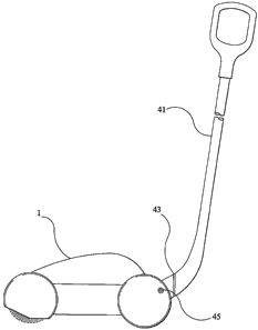
A handle 33 is attached to the body 1 in the region of the
rear compartment 3, the body being formed with a recess 35
beneath the handle to allow the handle to be gripped while
maintaining a low profile for the surface cleaning
apparatus. The handle 33 may be in two parts, a first part
37 which is secured to the body 1 and a second part 39
which can be removed from the first part and replaced by a
longer handle part 41 as shown in Figure 3. The longer
handle part 41 is provided with swivel means 43 to allow
the handle part 41 to rotate about the axis thereof
relative to the body 1 and with pivot means 45 to allow the
handle part to pivot about an axis transverse to the axial
direction of the handle part to enable the surface cleaning
apparatus to be steered by the user. As an alternative to
CA 02451958 2003-12-17
WO 03/007776 PCT/GB02/03309
- 13 -
interchangeable handles, the handle part 41 may be
removably engageable with the handle part 33. In such a
case, the handle part 33 is arranged such that the swivel
means 43 functions only in certain positions of the handle
part 33 in order that movement can be inhibited when the
handle part 33 is used alone.
As will be apparent particularly from Figure 3, the
bristles of the brush arrangement 11 extend outwardly from
the aperture in the forward compartment 9. In order to
remove stubborn debris and/or to revitalise carpet the
lower front region of the forward compartment may be
chamfered, or the front region of the forward compartment
may be movable (including removable), to increase the
exposure of the bristles in this region. In this way, the
forward part of the apparatus may be inclined relative to
the surface to be cleaned, thereby increasing contact
between the bristles and a surface to be cleaned and, on
some surfaces, increasing the depth to which the bristles
penetrate and clean the surface.
Although not shown, an auxiliary rotary brush may be
provided at that side of the brush arrangement 11 which
incorporates the roller 27 and the belt 29. Such an
auxiliary brush is described, for example, in GB-A-1 547
286. Such an auxiliary brush is able to sweep debris into
the path of the brush arrangement 11 which might otherwise
be missed due to the lack of bristles in the region of the
roller 27. The auxiliary brush may be driven by any
suitable means, such as gearing from the brush arrangement
11 or by friction with the surface to be swept, and is
suspended from and extends outwardly beyond the body 1.
The auxiliary brush may comprise a cylindrical body
rotatable about an axis which is inclined to the vertical
by about 10 degrees so as to extend outwardly beyond the
CA 02451958 2003-12-17
WO 03/007776 PCT/GB02/03309
- 14 -
body 1. Bristles protrude radially outwardly from the
periphery of the cylindrical body, but need not be
perpendicular to the axis of rotation and may preferably be
at an angle of about 80 degrees to the axis of rotation so
as to form a cone which increases in cross-section with
increasing distance from the body 1.
Although not shown, the front part of the forward
compartment 9 may be removed to expose the bristles at the
front of the apparatus. This effectively increases the
aperture in the forward compartment which would seriously
impair the effectiveness of a suction cleaner, but in the
present invention can effectively be used to assist in the
sweeping of stairs, cleaning upholstery and carpets in
vehicles and the like operations where a greater exposed
area of bristles can be useful. As an alternative to
removing the front part of the compartment 9, the front
part may be movable, for example pivotable or slidable,
relative to the remainder of the compartment in order to
expose the bristles.
Although not shown, the rear compartment 3 may be provided
with ground-engaging wheels in order to assist mobility of
the surface cleaning apparatus. The ground-engaging wheels
may, for example, be formed externally in the side regions
of the rear compartment 3 or may be provided within
recesses formed at least partly beneath the rear
compartment 3.
Although the illustrated embodiments of the present
invention are intended primarily for domestic use, the
surface cleaning apparatus can also be used outdoors or in
workshops if desired. However, it may be preferable to
provide a more rugged design specifically adapted for such
use.
CA 02451958 2003-12-17
WO 03/007776 PCT/GB02/03309
- 15 -
In use of the surface cleaning apparatus according to the
invention, as shown in Figures 1 and 2, the apparatus is
placed upon a surface to be swept, such as a carpet, and
the switch operated to energise the motor and consequently
to rotate the brush arrangement to sweep debris from the
surface and then propel the debris up and over the inclined
wall 15 and into the intermediate compartment 17 where it
is temporarily stored. As the surface cleaning apparatus
is moved over the surface with the brush arrangement 11
rotating, any further debris is similarly swept from the
surface and propelled up and over the wall 15 and into the
intermediate compartment 17. The surface cleaning
apparatus is extremely portable and can be employed
wherever it may be required. For example, it can be used
to sweep stairs without the need for electrical leads or
suction hoses. The shape of the apparatus with the rounded
shape of the rear compartment as illustrated facilitates
movement of the apparatus over stairs, but ground engaging
wheels may be provided to further facilitate such sweeping
operations.
When the intermediate compartment 17 is to be emptied, one
wall of the compartment is removed as explained above and
the debris can readily be discharged. The removable wall
is then replaced. Alternatively, the intermediate
compartment may be in the form of a tray which can be
removed and emptied so as to discharge debris.
When the surface cleaning apparatus is not in use it can be
stored, for example either in a cupboard or the like or
plugged into a mains supply in order to recharge the
battery 7.
Thus the surface cleaning apparatus of the present
invention incorporates an electrically driven brush
CA 02451958 2003-12-17
WO 03/007776 PCT/GB02/03309
- 16 -
arrangement. The brush arrangement is not driven by
frictional forces between the surface cleaning apparatus
and the surface over which it is to be moved. Thus,
efficiency of the apparatus is not dependent on the nature
of the frictional contact. Further, the apparatus does not
rely on suction means to draw the debris into a storage
chamber. Thus, efficiency of the apparatus is not
dependent on the effectiveness of suction means and the
substantial power drain of suction means on the
rechargeable battery is avoided. The provision of the
motor at the rear of the apparatus eliminates the need for
increased height should the motor be positioned over the
compartment for collecting dust and the like and also
provides effective full width cleaning which would not be
possible if the motor was to be positioned within the
compartment for collecting debris. In such a position,
debris is likely to accumulate around the motor and cause
blockages. The present invention overcomes this problem by
passing the drive means for the brush arrangement at least
partly through the debris compartment.
Referring to Figures 4, 5 and 6, apparatus 102 for cleaning
a surface 104 by sweeping comprises a housing 106, suitably
of moulded plastics material, and effectively having three
compartments. A rear compartment 108 houses an electric
motor 110 and a rechargeable battery pack 112. The battery
pack 112 may be connected to a mains power supply (not
shown) for recharging the battery pack. The battery pack
may either be connected to the mains supply whenever the
apparatus is not in use or at suitable times when the
battery pack has become depleted. Switch means 113 is
provided to permit a user to energise and de-energise the
motor 110 as desired. As an alternative to a rechargeable
battery pack, the apparatus could employ disposable
batteries or be mains powered.
CA 02451958 2003-12-17
WO 03/007776 PCT/GB02/03309
- 17 -
A forward compartment 114 houses a transversely-arranged
elongate rotatable brush arrangement 116, with bristles
118. Such elongate rotatable brush arrangement 116 is
sometimes known as a brush bar. The bottom of the forward
compartment 114 is open at 120 to allow the bristles 118 of
the elongate brush arrangement 116 to contact a floor,
carpet or the like over which the apparatus is to be
propelled. The rear of the forward compartment is a
rearwardly inclined wall 122 which allows debris, such as
dust, dirt and the like to be propelled up the wall due to
rotation of the brush arrangement 116 and to pass over the
wall into an intermediate compartment 124. The front of
the forward compartment is provided with a cover (not
shown) which may be removable if desired. Debris
accumulating in the intermediate compartment 124 can be
removed by opening a cover 126. The wall 122 extends
upwardly to about the same height as the top of the
elongate brush arrangement 116 and may be angled rearwardly
(i.e. away from the forward compartment) such as at an
angle of about 18 degrees. The precise angle is not
important, but the inclination facilitates the passage of
the debris up and over the wall 122 and at the same time
facilitates retention of the debris within the intermediate
compartment 124.
The elongate brush arrangement 116 is rotated by the motor
110 by way of toothed rollers 128, 130 attached to the
motor and to the brush arrangement, respectively, and by
way of a toothed belt 131, for example of elastomeric
material, extending around the two rollers. The toothed
belt 131 is enclosed within a tunnel 132 where it passes
through or alongside the intermediate compartment 124 in
order to prevent the ingress of debris into the rear
compartment 108.
CA 02451958 2003-12-17
WO 03/007776 PCT/GB02/03309
- 18 -
An auxiliary brush means 134 is provided extending
outwardly from the housing 106 at the right hand side of
the elongate rotatable brush arrangement 116 as viewed from
above and behind the apparatus 102. The auxiliary brush
means 134 is of substantially circular form and is
supported for rotation about an axis 136, which may be
vertical or inclined to vertical, such as at an angle of
about 10 degrees to vertical. The auxiliary brush means
134 has a body 138 provided with radial bristles 140 which
are inclined at an acute angle to the axis of rotation 136
so as to effectively form a conical arrangement increasing
in cross-section with increasing distance from the body
138.
The auxiliary brush means 134 is rotatably driven from the
rotating elongate brush arrangement 116 by a gear wheel 142
at the end of the elongate brush arrangement 116 which
meshes with a further gear wheel 144 on the body 138 of the
auxiliary brush means 134. The auxiliary brush means 134
is caused to be rotated in an anti-clockwise direction
denoted by arrow 146, as viewed from above and behind the
apparatus 102. During such rotation of the auxiliary brush
means 134, a peripheral region thereof rotates from a
sideways-directed position 148 (Figure 6) outside the
housing 106 to an opposed sideways-directed position 150
covered by the housing 106, through a forwardly-directed
position 152.
The apparatus 102 is provided with a handle 154 by means of
which it can be propelled at least in a forwards direction
156. Wheels 158 and 160 are provided to enable or assist
manual propulsion of the apparatus across the surface 104
to be swept, such as a floor, stairway or upholstery. The
handle 154 could be longer, or be of a different shape or
form, as required.
CA 02451958 2003-12-17
WO 03/007776 PCT/GB02/03309
- 19 -
The rotating auxiliary brush means 134 does not rely on
contact with the surface 104 for its rotation and therefore
provides more efficient sweeping of edge regions of the
surface 104 regardless of the nature of the surface 104.
Furthermore, the direction of rotation 146 of the auxiliary
brush means 134 ensures that debris is swept positively by
the auxiliary brush arrangement 134 into a position ahead
of the rotating elongate rotating brush assembly 116, ready
to be picked up by the elongate brush arrangement 116.
If desired, instead of or in addition to the auxiliary
brush means 134 provided extending outwardly from the right
hand side of the housing 106, a similar auxiliary brush
means (not shown) could likewise be provided extending
outwardly from the left hand side of the housing 106 and
driven from the opposite end of the elongate brush
arrangement 116. Such additional or alternative auxiliary
brush means differs from the auxiliary brush means 134 only
in that it is caused to rotate in a clockwise, rather than
anti-clockwise, direction as viewed from above and behind
the apparatus 102.
Instead of the apparatus 102 being provided with a battery
or mains powered electric motor 110 to drive the elongate
brush arrangement 116 and hence the auxiliary brush means
134, a known form of friction drive means (not shown),
resulting from propulsion of the apparatus 102 along the
surface 104, may be utilised to effect rotation of the
elongate brush arrangement 116 and hence rotation of the
auxiliary brush means 134.
An alternative embodiment of apparatus according to the
present invention is shown in Figure 7. Such alternative
embodiment comprises an upright vacuum cleaner apparatus
102A, having a housing 106A with wheels 158A and 160A, a
CA 02451958 2003-12-17
WO 03/007776 PCT/GB02/03309
- 20 -
rotating elongate brush arrangement 116A and an auxiliary
brush means 134A. The apparatus 102A is constructed in
substantially similar manner to the apparatus 102 of
Figures 4, 5 and 6, with the main exception that instead of
the debris-collecting compartment 124 of Figure 5, a
debris-collecting container 124A, which may include a bag,
is provided between a handle 154A and the housing 106A and
connected by a well-known form of suction arrangement (not
shown) to the housing 106A.
A further embodiment of apparatus 102B according to the
present invention is shown in Figure 8. Here the housing
106B incorporates components similar to those of the
housing 106 of Figures 4, 5 and 6 including wheels 158B
and, in particular, an elongate rotating brush arrangement
116B with an auxiliary rotating brush means 134B driven
therefrom. However, no debris-collecting compartment is
provided inside the housing 106B. Instead, the housing
106B is provided with a tubular portion 162 which is
demountable on, or may be fixed to, a debris-receiving
flexible hose 164 connected to a well-known form of suction
vacuum cleaner 166, which may be of cylinder form, mounted
on wheels 168. Electrical wiring 170 can be incorporated
in the hose 164 by means of which mains electrical power
can be supplied from the vacuum cleaner 166, and through a
connector 172 and wiring 174 in the tubular portion 162, to
an electric motor 110B where provided in the housing 106B
for driving the elongate rotating brush arrangement 116B
and the auxiliary brush means 134B. Of course, such wiring
170 would be unnecessary where the elongate brush
arrangement 116B and the auxiliary brush means 134B driven
therefrom, is caused to be rotated by the friction means
previously described. Alternatively, the elongate brush
arrangement 116B and the auxiliary brush means 134B may be
caused to be rotated by means of a (rechargeable) battery
CA 02451958 2003-12-17
WO 03/007776 PCT/GB02/03309
- 21 -
or an air turbine driven by air passing along the tubular
portion 162. The housing 106B with its included components
could be provided as an accessory for existing vacuum
cleaners of cylinder form.