Note: Descriptions are shown in the official language in which they were submitted.
CA 02452378 2003-12-29
WO 03/005524 PCT/US02/21216
Description
SYSTEM FOR ESTIMATING THE FREQUENCY OF THE POWER SIGNAL
ON A POWER TRANSMISSION LINE
Technical Field
This invention relates generally to determination of
the power signal frequency for use in protective relay
operations, and more specifically concerns a system for
maintaining the accuracy of the power system frequency
determination if one or more of the individual phase voltage
poles are open, or if there are other error conditions in the
power system or power system instrumentation transformers.
Background of the Invention
Protection functions for an electric power system,
such as carried out by a protective relay, other protection or
monitoring device, often require an accurate knowledge of the
power system frequency, i.e. the frequency of the power signal
being provided to the system's customers. Misoperations of a
protective relay can occur if the system frequency is not
accurately known and tracked, as the frequency may change from
nominal frequency. A memory polarized distance element is an
example of a protective element in a relay which can misoperate
if the system frequency is not accurately tracked. Accurate
frequency information is important in a number of protection
operations.
Power system frequency can be affected by a number of
factors, including operating stress on the system due to high
demand, as well as other factors, such as a sudden mismatch of
generation to load caused by the liberation of a system fault and
the resulting increase in system transfer impedance. Frequency
is generally determined by selecting a single phase of the
voltage on the power line, usually A-phase, and then making a
system frequency determination from that voltage signal, based on
the frequency of that single phase voltage. The frequency
CA 02452378 2008-03-06
2
determination can be accompli_shed by any one of a number of
conventi_onal, well known frequency determining Lechniques.
Generally, such a system works well. However, if the
selected phase vol.tage is de-energi_zed, such as if Lhe pole
opened due to a si_ngl.e pole Lripping operaLi.on, or iC Lhere is
a fuse failure of the VT (voltage Lransformer) supplyi_ng thaL
phase voltage to the device or if other factors produce a
frequency distortion of that single phase vol.tage, the ability
of the present system to produce an accurate determination of
system frequency is severely impaired, if not eliminated. I?or
instance, an open pole or blown VT fuse will resulL in a lack
of frequency determinaLion. `I'he occurrence oL Lhese evenLs
does not, however, remove the protective device from service
nor decrease the need for these devices to fulfill Lhei_r
functions of protection and monitoring.
Hence, i.t is desirable to increase Lhe reliability
and accuracy of power system frequency detcrminations, because
of Lhe importance of such frequency informaLion Lo Lhe corr.ect
operation of many pr_otecLive funcLions wiLh pr.otecLive relays.
Disclosure of the Invention
Accordingly, the present invention is a system for
determining the power system frequency whi.ch is used i.n the
protective relay operations for pr_otection and/or moni_toring
of Lhe power sysLem, compr_isi_ng: means for obtaini_ng Lhree
phase voltages on Lhe power l_i_ne by elemenLs which are local
to the protective relay; a calculating circui_L for producing a
composite voltage of the three phase voLtages in accordance
with a preselected equation; and means for estimating the
power system frequency from the composite voltage, where-i_n
said power system fr.equency i_s used by the pr.otective rel.ay i_n
its protecti.ve functions for the power system.
Accordi_ng Lo an aspect, the invention relates Lo a
sysLem for determ.-i.ning power system frequency for use in a
protective relay oper_ating Lo protect or moni_tor Lhe power
system, comprising: means for obtaini_ng three phase vol.Lages
on the power line by elements which are local to the
protective relay; and a calculating circuit for pr_oduci_ng a
CA 02452378 2008-03-06
2a
composite voltage of the three phase voltages using the
following equation:
CV~ +V~ )]-K
Ux= Vj - 2
where V; is the composite voltage, K:i.s the scaler
quantity and VA, VB, and Vc are the three phase voltages,
respectively.
Brief Description of the Drawings
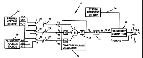
Figure 1 is a block diagram showi.ng the system of
the present i_nvention.
CA 02452378 2003-12-29
WO 03/005524 PCT/US02/21216
3
Figure 2 is a table showing the operation of one
portion of the system of Figure 1.
Best Mode for Carrying Out the Invention
Figure 1 shows the system 10 of the present invention,
the system being used to develop a reliable determination of
power system frequency on frequency output line 12, from three
phase voltages (VA, VB and Vc), provided either by a primary
source 14 or an alternate source 16 from the power line. The
respective voltages, primary and alternate, are labeled VAy, VBy
and Vcy and VAZ, VBZ and VcZ to identify the three phases and
distinguish the two sources. The voltages are from two different
sources of voltages from the power line.
Line switches 20-22 are associated, respectively, with
each phase, to both primary and alternate sources and operate
between two positions. Switches 20-22 are controlled to be in
position 1 for the primary source, unless (1) an alternative
source enable signal is provided, which means that an alternative
source is available, if desired, and (2) an alternate source
setting is actually provided by the relay, when an alternate
source is in fact desired. Alternate sources are not, however,
necessary to the invention.
The outputs from switches 20, 21 and 22 are applied,
respectively, to one side of switches 28-30. Switches 28-30
operate between two positions. Position 2 is the normal state or
position of the switches, and they are in this position when the
pole for the phase voltage is closed. Each phase of the source
voltage will be applied directly through their associated switch
28-30 when these switches are in switch position 2.
The switches are moved to position 1, for each phase,
under the following conditions. Switch 28 will be moved to
position 1 independently when there is an A-phase pole open
condition, a three-pole open condition or a loss of potential
condition and the alternate source VA voltage is not available,
as determined conventionally by the protective device. When
switch 28 is in position 1 (open), there will be no voltage VA on
line 34. Switch 29 will be moved to position 1 (open) when there
CA 02452378 2008-03-06
4
is a 33- hase
p pole open position, a Lhree-poLe open cond.iLion
or loss of potential condi_Lion and the alternaLe source V;; i.s
noL available, again as determined by Lhe relay. When sw:i_tch
29 is in position 1(open), there will. be no vo.ltage on a.ine
36. Otherwise, the voltage on line 36 will be the B-phase
voltage VB from the source 14 (or source 16) . SwiLch 30 is
moved Lo position 1. (open) when the:re is a C-phase pole open
position, a th:rce-pol.e open condition or a loss of potential
condition and Lhe alternate source Vc voltage is not available.
When switch 30 is in i.Ls open position, the.re _i_s no volLage orl
line 38, otherwise, the voltage i_s Vc from the voltage source,
either primary or alternate.
The voltages on lines 34, 36 and 38 (whether present
or not) are applied to a composite voltage calculation c:ircu:it
40 .'Phe composi_te volLage calcul.ator 40 produces a compos i.te
signal from Lhe Lhr.ee volLa.ge :i.npuLs on lines 34,36 and 38 in
accordance wi.th the fol.lowing expression:
V8 +Vr
VX = V, - 2 =K
K is a scaler quanti_Ly provided by element 42, the value of
which depends upon the posiLion of swiLches 34, 36 and 38 in
accordance wi_th the tablc of Fi.gur_e 2. `I'he purpose ot the
scaler function K, which -i_s an adapti_ve gain clemcnL, and
which follows the particular power :line operaLing condiL:i_ons
(in particular, the open/close position of the three poles) is
to adjust the composite voltage value from the above
expression to a constant magnitude signal which i_s applied to
the r_emai_nder of the circuit o.f. Figure 1.
`I'he ouLpuL of vo1 Lage ca1 culaLor c i rcu_i L(10 V,.; _is
applied to a conventional low pass fi]_Ler 44 which filLc.rs out
the hi..gher ha.rmoni.cs of the input signal, leaving just the
fundamental frequency portion of V,.,, r_ ef err. ed to as Võfur,d .'I'he
V,xful,a signal is applied to a frequency esti_mator 46.
CA 02452378 2008-03-06
4a
Estimator 46 is responsive to the applied voltage si.gnal to
produce an esti_mate (deter_m.inati_on) oE th.e frequency. `t'he
frequency esti.mation is co:nventional, and can ei.ther bc done
in hardware or software. `1'echni_ques include iero cross i.ng,
various filtering
CA 02452378 2003-12-29
WO 03/005524 PCT/US02/21216
approaches, phase angle shift determination and still others. It
should be understood that a wide variety of conventional
techniques can be used to produce the estimate of the frequency
from the V,fund signal applied to it.
5 The output of frequency estimation circuit 46 is
referred to as the local frequency fLOCõL. When switch 48 is in
its normal position (position 1), the fLOCA-L signal is the system
frequency output which is supplied to the protection algorithms
of the relay.
The frequency estimation circuit 46 is responsive to a
control signal 50 which "freezes" the estimated frequency value
at the last determined value if the relay recognizes either a
transient in the system operation, or there has been a trip
signal provided by the relay. In such a case, the frequency
estimation is maintained at the last value and will not change
until the control signal 50 goes away.
Referring to switch 48, position 1 is selected when
local, i.e. primary or alternate, voltage sources are available
and operating. If neither of the local voltages, either primary
or alternate, are available, then a remote frequency value
(fREMOTE) from another source can be used to produce the frequency
output signal for the protection functions, when switch 48 is in
position 2.
Hence, a system has been disclosed which maintains the
reliability and accuracy of system frequency determinations, even
when one of the phase voltages from which the decision has been
made is eliminated because its associated pole is open. Other
factors adversely affecting frequency can also be accommodated.
The system calculates a composite of the three individual phase
voltages VA, VB and Vc from a local source in accordance with a
particular formula to arrive at a composite voltage, referred to
as V,,,, which is used for the frequency estimation. The present
system results in a more reliable and accurate system frequency
determination. If local voltage sources, either primary or
alternate, are not available, the system has the capability of
selecting remotely originated frequency information for operation
of the protective device.
CA 02452378 2003-12-29
WO 03/005524 PCT/US02/21216
6
Although a preferred embodiment of the invention has
been disclosed here for purposes of illustration, it should be
understood that various changes, modifications and substitutions
may be incorporated without departing from the spirit of the
invention, which is defined by the claims which follow.
What is claimed is: