Note: Descriptions are shown in the official language in which they were submitted.
CA 02452584 2003-12-31
WO 03/006337 PCT/EP02/07464
SELF-ABSORBING GAS-BARRIER RECEPTACLE FOR FOOD PACKAGING AND
FOOD PACKAGE OBTAINED THEREFROM
The present invention relates to a receptacle for food packaging suitable for
use in vacuum
or modified atmosphere packaging of food products that tend to exude fluids.
The present invention is also directed to the use of said receptacles in food
packaging
processes and to the food packages obtained thereby.
BACKGROUND OF THE INVENTION
It is conventional practice to display meat, poultry, and other food products
in individual
packages which comprise a supporting tray with an absorbent pad placed between
the upper
surface of the tray and the food product, to absorb any juices or liquids,
such as blood, exuded
from the food product. To prevent or retard any migration of the liquids from
the absorbent
pad back to the food product, the absorbent pads are typically enveloped in a
moisture
impermeable film that has a number of perforations on the surface facing the
tray.
The use of an absorbing pad suffers from the big disadvantage of the labor
cost involved in
inserting it into a tray, including the costs of a padding machine
specifically designed for this
purpose. Another disadvantage of this system is the aesthetics of the pad when
filled with
liquids, particularly blood. Still another disadvantage can be experienced
when the pad is
saturated with the liquids, as it then tends to stick to the food product and
must be physically
separated therefrom by the consumer after the package is opened.
One approach to solve the above problems has been to provide a packaging tray
having
integral means for removing the fluids exuded from the food products, without
requiring the
use of a separate pad.
Several patents and patent applications have thus been published describing
receptacles for
packaging food products exuding fluids made with a laminate wherein an
absorbing layer is
positioned on top of a support layer or between a support layer and a food-
contact perforated
layer. Examples of these receptacles are described in GB-A-2,322,100, WO-A-
99/32286, EP-
A-878,481, EP-A-965,426, EP-A-642,907, and WO-A-98/12126.
1
CA 02452584 2003-12-31
WO 03/006337 PCT/EP02/07464
None of these documents however makes reference to the possibility of
obtaining a self
absorbing tray (i.e. a tray with integral means capable of absorbing the
fluids) having gas-
barrier properties.
On the other hand gas-barrier properties for a packaging material have become
extremely
important. By using gas-barrier packaging material, it is in fact possible to
package the food
product under a modified atmosphere especially designed to increase the shelf
life of the
packaged product. It is thus possible for instance to prepare suitable food
packages, e.g. meat
packages, at a central unit and then distributing them to supermarkets and
small shops.
EP-B-520,509 relates to a thermoformed self absorbing packaging element with
gas-barrier
properties. What is described in EP-A-520,509 is a container comprising an
absorbing layer
positioned between a substrate layer and an inner, food-contact porous
drainage layer wherein
gas barrier properties are provided by an outermost layer of a gas-barrier
material.
Following the teaching of EP-A-520,509 it is however not always possible to
obtain the
claimed gas-barrier properties. On the contrary, in most of the cases and
independently on the
I S gas-barrier properties of the outer gas-barrier layer and of the gas-
barrier film that closes the
mouth of the tray, the atmosphere within a package obtained by following the
teaching of EP-
A-520,509 does equilibrate with the outer atmosphere in a very short time. In
fact when a
foamed or a fibrous layer is employed in the construction of the tray, gases
can permeate
through the lateral edges of said foamed or fibrous gas-permeable layer and
easily move
within said layer through the walls of the container, passing through the
porous drainage layer.
More particularly when a foam layer, such as a polystyrene foam layer, is
employed as the
substrate structural layer, even if an outer layer and a lid with a very low
OTR are employed,
the atmosphere within the package re-equilibrates with the outer atmosphere in
just few hours.
In such a case it is almost immaterial whether the heat-sealing of the lid to
the tray rim is
carried out by using conventional pressure conditions or a much higher
pressure, as in any
case the foamed cells with not be compressed to such an extent to exclude air
permeation at
the sealing area.
2
CA 02452584 2003-12-31
WO 03/006337 PCT/EP02/07464
Also when a rigid layer is employed as the substrate structural layer but the
absorbing layer
is obtained, as indicated in EP-A-520,509, by a formulation of expanded and/or
fibrous
material, then in most of the cases air may pass through the side edges of
such a highly gas
permeable absorbing layer entering into the end package.
WO 00/46125 describes a self absorbing food-packaging tray that comprises a
"space"
sealed in a fluid-tight manner and filled by a material from which the wall
structure is made.
The sealed space is obtained by bringing together the outer surface and the
inner surface of the
base wall. According to WO 00/46125 this can be obtained either by solvent or
paint coating
the distal edges of the tray rim to bridge the inner and the outer surfaces
across the thickness
of the wall structure at said peripheral edge (and in this case the sealed
space and the tray
would be conterminous) or by bringing together the inner and the lower
surfaces by an
ultrasonic seal or by the application of heat and pressure in a conventional
thermoforming
step. In certain instances, depending on the type of inner liners employed
and/or of the way
the tray is lidded, a gas-barrier package might be obtained.
No details are given in WO 00/46125 on how the ultrasonic sealing or the
thermoforming
steps must be performed to achieve sealing of the outer surface to the inner
one with
"disappearance" of the porous layer in-between at the sealing area. If
sufficiently high
pressures are exerted to fracture the intermediate porous layer and allow
sealing of the inner
surface to the outer one, the risk of cracking of the structure in the area
closed to said seal and
therefore the risk of leakers would probably be high.
Also difficult in the system of WO 00/46125 would be to guarantee consistent
results in
industrial conditions. Finally, with reference to what appears to be a
preferred embodiment for
the manufacture of a gas-barrier tray, where the structure comprises two gas-
barrier liners, one
on the outer surface and the other on the inner surface, recyclability of the
skeleton would be
impaired and the costs of the final product remarkably increased.
Thus, although WO 00/46125 describes a gas-barrier package using self
absorbing barrier
foam tray, room for improvement exists in pursuit of a gas-barrier package
based on a self
absorbing foam tray.
3
CA 02452584 2003-12-31
WO 03/006337 PCT/EP02/07464
It is therefore an object of the present invention to provide a receptacle for
food packaging
which is capable of absorbing fluids exuded from the food product placed
thereon without
requiring the use of a separate pad and that at the same time may guarantee
that the end
package obtained by sealing to the receptacle flange a gas-barrier film will
have gas-barrier
properties.
SUMMARY OF THE PRESENT INVENTION
In a first aspect the present invention is directed to a receptacle suitable
for food packaging
which comprises a bottom or base portion defining a storage compartment or
zone and a
flange circumferentially extending all around the receptacle contour providing
an area for the
closing lid to be sealed, said receptacle being made of a mufti-layer
thermoplastic structure
comprising at least
(i) an upper liquid absorbent layer that is devised to be either in direct
contact
with the food product to be packaged in the receptacle or separated therefrom
by
one or more liquid pervious layers allowing passage of liquids from the
receptacle
inner surface into the absorbent layer, and
(ii) a lower non-perforated liquid and gas-barrier thermoplastic film,
characterized in that the surface exposed along a closed line in the
circumferential
flange is of the lower non-perforated liquid and gas-barrier thermoplastic
film.
The terms "upper" and "lower" as used herein refer to the relative positioning
of the layers
concerned in the overall mufti-layer structure, wherein "upper" means closer
to the product to
be packaged and "lower" means further from the food product to be packaged.
In a second aspect the present invention is related to a method of packaging a
food product
that tends to exude fluids, by loading it into the storage compartment of the
receptacle of the
invention, optionally vacuumizing and/or gas flushing the receptacle with a
suitably selected
gas or gas mixture that would extend the shelf life of the packaged product
and closing said
receptacle by means of a gas-barrier lid sealed to the exposed surface of the
liquid- and gas-
barrier film along a closed line in the circumferential flange of the
receptacle.
4
CA 02452584 2006-06-07
77572-19
In a third aspect the present invention is
directed to a gas-barrier package for food products that
tends to exude fluids comprising a food product loaded onto
or into a receptacle according to the present invention
closed by a gas-barrier lid, disposed over the food product,
and sealed to the exposed surface of the liquid- and gas-
barrier film along a closed line in the circumferential
flange of the receptacle.
According to another aspect of the present
invention, there is provided a receptacle useful in
packaging a food product between the receptacle and a lid,
the receptacle comprising: a product storage zone for
supporting the product; and a sealing zone circumferentially
extending around the product storage zone; and a mufti-layer
structure comprising: a liquid absorbent layer integral
with the mufti-layer structure; a gas-barrier film; and a
support layer, wherein: the mufti-layer structure has a
product storage side; in the product storage zone of the
receptacle, the liquid absorbent layer is closer than the
gas-barrier film to the product storage side of the multi-
layer structure; and in the sealing zone of the receptacle,
the gas-barrier film forms the surface of the product
storage side of the mufti-layer structure, whereby the lid
may be sealed directly to the gas-barrier film in the
sealing zone.
According to still another aspect of the present
invention, there is provided a receptacle useful in
packaging a food product between the receptacle and a lid,
the receptacle comprising: a product storage zone for
supporting the product; and a sealing zone circumferentially
extending around the product storage zone; and a mufti-layer
structure comprising: a liquid absorbent layer integral
5
CA 02452584 2006-06-07
77572-19
with the mufti-layer structure; and a gas-barrier film,
wherein: the mufti-layer structure has a product storage
side; in the product storage zone of the receptacle, the
liquid absorbent layer is closer than the gas-barrier film
to the product storage side of the mufti-layer structure; in
the sealing zone of the receptacle, the gas-barrier film
forms the surface of the product storage side of the multi-
layer structure, whereby the lid may be sealed directly to
the gas-barrier film in the sealing zone; and the multi-
layer structure further comprises a liquid pervious layer
forming the surface of the product storage side of the
mufti-layer structure in the product zone of the receptacle,
the liquid pervious layer being adapted to allow liquid from
the product to pass through the liquid pervious layer to the
liquid absorbent layer.
According to yet another aspect of the present
invention, there is provided a receptacle useful in
packaging a food product between the receptacle and a lid,
the receptacle comprising: a product storage zone for
supporting the product; and a sealing zone circumferentially
extending around the product storage zone; and a mufti-layer
structure comprising: a liquid absorbent layer integral
with the mufti-layer structure; and a gas-barrier film,
wherein: the mufti-layer structure has a product storage
side; in the product storage zone of the receptacle, the
liquid absorbent layer is closer than the gas-barrier film
to the product storage side of the mufti-layer structure; in
the sealing zone of the receptacle, the gas-barrier film
forms the surface of the product storage side of the multi-
layer structure, whereby the lid may be sealed directly to
the gas-barrier film in the sealing zone; and the liquid
absorbent layer comprises a material selected from an open
cell foam and a superabsorbent polymer.
5a
CA 02452584 2006-06-07
77572-I9
BRIEF DESCRIPTION OF THE FIGURES
Figure 1 is a sectional view of a first preferred
embodiment of the receptacle of the present invention;
Figure 2 is a sectional view of a second preferred
embodiment of the receptacle of the present invention;
Figure 3 is a sectional view of a third preferred
embodiment of the receptacle of the present invention;
Figure 4 is an enlarged sectional view of the
flange portion of a receptacle of the first preferred
embodiment illustrated in Figure 1;
Figure 5 is a sectional view of a package of the
present invention obtained using the receptacle of Figure l;
Figure 6 is a sectional view of a package of the
present invention obtained using the receptacle of Figure 3;
Figure 7 is a cross-sectional view of one
preferred mufti-layer thermoplastic structure suitable for
the manufacture of a receptacle according to the present
invention;
Figure 8 is a cross-sectional view of another
preferred mufti-layer thermoplastic structure suitable for
the manufacture of a receptacle according to the present
invention;
Figure 9 is a cross-sectional view of still
another preferred mufti-layer thermoplastic structure
suitable for the manufacture of a receptacle according to
the present invention.
5b
CA 02452584 2006-06-07
77572-19
DETAILED DESCRIPTION OF THE INVENTION
In a first aspect the present invention is
directed to a receptacle suitable for food packaging which
comprises a bottom or base portion defining a storage
compartment or zone and a flange circumferentially extending
all around the receptacle contour providing an area for the
5c
CA 02452584 2003-12-31
WO 03/006337 PCT/EP02/07464
closing lid to be sealed, said receptacle being made of a multi-layer
thermoplastic structure
comprising at least
i) an upper liquid absorbent layer that is devised to be either in direct
contact with the
food product to be packaged in the receptacle or separated therefrom by one or
more
liquid pervious layers allowing passage of liquids from the receptacle inner
surface
into the absorbent layer, and
ii) anon-perforated liquid and gas-barrier thermoplastic film,
and being characterized in that the surface exposed along a closed line in the
circumfersntial
flange is of the lower non-perforated liquid and gas-barner thermoplastic
film.
In a preferred embodiment the receptacle has the shape of a tray, comprising a
bottom
portion and side walls integral with said bottom and with each other defining
a storage
compartment, and the flange extends outwardly from the top edges of the side
walls, typically
in a plane substantially parallel to that of the bottom portion. Said
embodiment is illustrated
in Figures 1 and 2.
In another embodiment of the present invention, the receptacle is an almost
flat support, i.e.
a dish-shape receptacle, that may have e.g. a rectangular, round, oval or
squared surface and
the flange is the outward edge of said flat support. Said latter embodiment is
illustrated in
Figure 3.
In both embodiments, the surface exposed along a closed line in the
circumferential flange,
i.e. in the closed line provided for sealing the lid to the receptacle, is the
surface of the non-
perforated liquid- and gas-barrier film. By sealing a liquid- and gas-barrier
lid to the exposed
surface of the liquid- and gas-barrier film of the receptacle along said
closed line in the
circumferential flange, it is then possible to obtain a self absorbing, gas-
barrier, package.
The exposure of the liquid- and gas-barrier film along the sealing line in the
receptacle
according to the present invention is preferably achieved starting from a dish-
or tray-shaped
laminate, including both the absorbent layer and the liquid- and gas-barrier
film and removing
the uppermost layers, including the absorbent layer and any liquid pervious
layer on top
thereof, along said sealing line.
6
CA 02452584 2003-12-31
WO 03/006337 PCT/EP02/07464
Alternatively however it can also be achieved starting from a dish- or tray-
shaped laminate
that comprises the absorbent layer but not the liquid- and gas-barrier film
and adhering the
liquid- and gas-barrier film to the shaped laminate in such a way that the
liquid- and gas-
barrier film extends circumferentially over the flange edge of the dish- or
tray-shaped
laminate.
Still alternatively it would be possible to obtain the end receptacles
starting from a
continuous sheet or from discrete pieces of a flat laminate of the overall
multi-layer structure
wherein however the size and the position of the laminate of the upper layers,
i.e. those. on top
of the liquid- and gas-barrier thermoplastic film, are suitably set to provide
directly for the
desired product upon in registry thermoforming.
According to a most preferred embodiment of the present invention the
thermoplastic
multi-layer sheet of the base portion of the receptacle of the invention
comprises in addition to
a liquid absorbing layer and a liquid- and gas-barrier thermoplastic film,
also a structural
support layer that is preferably "lower" with respect to the liquid- and gas-
barrier
1 S thermoplastic film, and a liquid-pervious, food-contact layer.
The liquid absorbing layer may comprise any type of liquid absorbing material.
In one preferred embodiment the liquid absorbing layer is made of an open cell
foam
material. A thermoplastic foamed sheet, in which the cells are at least for
their majority open,
i.e. intercommunicating, may in fact absorb and store liquids, similarly to a
sponge. Any type
of polymer than can be foamed giving an open cell structure can suitably be
employed for this
absorbent layer. Examples of suitable polymers include polyethylenes, either
homo-polymers
or copolymers, such as ethylene-oc-olefin copolymers and ethylene-vinyl
acetate copolymers,
chlorinated polyethylenes, polypropylene-based resins, polystyrene and
polystyrene
copolymers, polyesters, such as polyethylene terephthalate, and the like
polymers. The
thickness of the open-cell foam absorbing layer is typically comprised between
about 0.1 mm
and about 10 mm, preferably between about 1 mm and about 4 mm. To increase
liquid
absorption by the open cell foam material it may be advisable to treat the
internal cell surface
7
CA 02452584 2003-12-31
WO 03/006337 PCT/EP02/07464
or at least the exposed surface thereof with a surfactant such as a salt of a
sulphonic acid or a
sulphuric ester.
When an absorbent layer of open cell foam material is employed, by suitably
selecting the
of open cells, the size of the cells and the thickness of the layer itself, it
is possible to obtain
thermoplastic sheets with an absorbency of from S00 to 1,500 ml/m2.
The open cell foam material may be used as the food-contact layer. However in
a preferred
embodiment said open cell foam absorbent layer is an internal layer, and the
mufti-layer
structure also comprises an upper, food-contact layer. The purpose of said
food-contact layer
is mainly that of hiding from view the liquid absorbed in the subsisting
absorbing layer, such
as the reddish meat drip or the yellowish poultry drip, and for this reason
said separate food-
contact layer is preferably opaque.
The use of a separate food-contact layer also improves the thermal molding
behavior of the
thermoplastic mufti-layer sheet in case it is thermoformed into a tray.
To allow the fluids to pass downward from the food contact surface into the
absorbing
layer, said upper food-contact layer is provided with perforations. Preferably
the perforations
have a small diameter, typically lower than 1.5 mm, preferably lower than 1.2
mm, and more
preferably lower than 1 mm, and are regularly distributed on the surface of
the sheet. The
number of perforations per m2 will depend on the average diameter of the
perforations and
may suitably be comprised between 500 and 40,000, preferably between 1,000 and
10,000.
The perforations are typically arranged in parallel rows that may be off set
one respect to the
other. The perforations are normally funnel-shaped towards the inside of the
sheet and may
have a round or slightly oval section, particularly in the regions where the
sheet is stretched to
form it into a tray. To further improve the absorbency of the absorbing layer,
preferably the
perforations extend also in said absorbent layer.
Said separate food contact layer can be of any thermoplastic material and the
preferred ones
are those providing for a good bond with the underlying open cell foam layer.
Generally the
same resin used for the open cell foam layer can be employed as a thick non-
foamed layer for
the food-contact layer. It would be further advantageous if also this layer
would be sealable to
CA 02452584 2003-12-31
WO 03/006337 PCT/EP02/07464
the lid to avoid that the absorbed drip percolates along the edges of the
absorbing layer if the
receptacle is positioned vertically. The thickness of said food-contact layer
is typically
comprised between about 3 pm and about 100 p.m, preferably between about 5 pm
and about
80 Vim, more preferably between about 8 ~m and about 50 p.m.
S Alternatively the food-contact layer is not perforated but is of a porous,
liquid pervious,
material. Examples of porous materials that may be pervious to liquids are
some non-woven
films or some void-containing films where the pattern of voids in the polymer
matrix allows
the passage of liquids by capillarity. Typically these liquid pervious films
are made of
polyolefin resins. In particular, commercially available non-woven
polyethylene films or void-
containing polypropylene films can suitably be employed for the food contact
layer.
In another embodiment the absorbing layer will comprise super absorbent
polymer (SAP)
particles, wherein the term "SAP" refers to any water-swellable homo- or co-
polymer known
in the art that may absorb and hold many times its weight of aqueous fluids.
Typically these
water-swellable polymers possess a structure in which a water-soluble polymer
has been made
insoluble by some process, typically by means of well-known mufti-functional
cross-linking
agents employed during or after polymerization, or by radiation cross-linking
or by thermal
treatments. Examples of water-swellable polymers that may suitably be employed
in the
absorbent layer of the present laminate include : poly(acrylic acid) salts,
poly(acrylate) salts,
polyvinyl alcohol-acrylic acid) salts, poly(isobutylene-malefic acid) salts,
poly(ether)-based
non ionic polymers, sodium carboxymethylcellulose, poly(vinylpyrrolidone),
acrylonitrile-
grafted starch, acrylic acid grafted-starch, and the like polymers.
Super absorbent polymers suitable for food packaging pertaining to the class
of
poly(acrylic acids) and poly(acrylates) are commercially available from e.g.
Dow and
Chemdal.
Another class of SAP particularly suitable for food packaging applications is
that of cross-
linked poly(vinylpyrrolidones), such as those commercially available from BASF
(Kollidon~).
9
CA 02452584 2003-12-31
WO 03/006337 PCT/EP02/07464
SAP are generally provided in the form of particulate materials, typically in
the form of
finely divided powders. For use in the manufacture of the absorbent layer of
the sheet of the
present invention they are preferably embedded in a polymeric matrix or bonded
with a
polymeric binder to allow either the extrusion thereof in a film layer, or its
distribution on a
thermoplastic substrate by a continuous or discontinuous coating process or by
spraying.
The overall amount of SAP that will be contained in absorbent layer will
depend on the
type of food product packaged and on the absorbency of the particular SAP
employed.
Typically for food packaging the maximum absorbency required is about 1,500
ml/m2.
When a SAP is employed for the liquid absorbing layer, said layer is an
internal layer and a
separate food-contact layer is necessarily present to avoid any active drawing
out of the fluid
from the food product that might occur if the food product is directly in
contact with the
absorbent. By suitably combining the dimension of the holes in the food-
contact layer, with
the thickness of this layer - depending on the weight and firmness of the food
product - it is
possible to prevent any direct contact between the food product and the
absorbing layer even
in correspondence of the holes, and by suitably selecting the number of holes
as well as the
more-or-less hydrophobic nature of the resin employed for this layer, it is
possible to achieve
the absorbency of all the fluids that are spontaneously generated by the
packaged food product
without the undesired drying out of the food product.
Using a SAP for the liquid absorbing layer, it might be desirable in certain
instances to
have in the structure an additional layer, a "distribution" layer, positioned
between the fluid
absorbing layer and the food-contact layer. Such a distribution layer might be
useful to
increase the efficiency of the absorbent layer by better distributing the
fluids therein. Said
optional distribution layer may have an absorbing capacity, but this is not a
necessary feature.
It may distribute the fluids that drip from the food-contact layer by a
chemical or a physical
mechanism. In the former case said layer will comprise a polar hydrophilic
polymer such as a
poly(acrylic acid), a poly(acrylate), or another similar polymer, that
preferably contains also
surface active agents. In the latter case the distribution of the fluids will
be obtained using a
CA 02452584 2003-12-31
WO 03/006337 PCT/EP02/07464
fibrous or slightly foamed open cell layer of a low melting polymer or a layer
where the
fibrous material is embedded into a polymer matrix that may optionally be
slightly foamed.
In line of principle any other alternative liquid absorbing material can be
used for the liquid
absorbing layer in the receptacle according to the present invention, the
above listed materials
representing only preferred embodiments thereof.
The mufti-layer thermoplastic structure of the receptacle of the present
invention also
comprises a thermoplastic liquid and gas-barrier film.
In the end package said thermoplastic film will be farther from the food
product than the
liquid absorbing layer. While in a preferred embodiment said liquid- and gas-
barrier film is
adjacent to the liquid absorbing layer, in some instances one or more
additional layers can be
imposed between the liquid absorbing layer and the thermoplastic liquid- and
gas-barrier film.
Actually the liquid- and gas-barrier film may be a monolayer film of a gas-
barrier resin but
preferably it is a mufti-layer film wherein at least one layer has gas-barrier
properties.
Non-limitative examples of gas-barrier polymers that can suitably be employed
for the gas-
barrier layer are EVOH, PVDC, and polyamides.
As used herein, the term EVOH includes saponified or hydrolyzed ethylene-vinyl
acetate
copolymers, and refers to vinyl alcohol copolymers having an ethylene
comonomer content
preferably comprised from about 28 to about 48 mole %, more preferably,' from
about 32 to
about 44 mole % ethylene, and even more preferably, from about 36 to about 42
mole
ethylene, and a saponification degree of at least 85 %, preferably at least 90
%.
The term PVDC refers to a vinylidene chloride copolymer wherein a major amount
of the
copolymer comprises vinylidene chloride and a minor amount of the copolymer
comprises one
or more unsaturated monomers copolymerisable therewith, typically vinyl
chloride, and alkyl
acrylates or methacrylates (e.g. methyl acrylate or methacrylate) or to a
blend thereof in
different proportions. Generally said PVDC contains plasticisers and/or
stabilizers as known
in the art.
The term polyamide is intended to refer to both polyamides and co-or ter-
polyamides. This
term specifically includes aliphatic polyamides or co-polyamides, aromatic
polyamides or co-
CA 02452584 2003-12-31
WO 03/006337 PCT/EP02/07464
polyamides, and partially aromatic polyamides or co-polyamides, modifications
thereof and
blends thereof.
As gas-barrier material also blends of EVOH with polyamides can suitably be
employed.
The gas-barrier material may also consist of a silica-coated film or anyway of
a film of
thermoplastic material with deposited a thin layer of inorganic metal oxides
(typically silica or
alumina) known to provide barrier properties in critical packaging
applications.
Preferably however the barrier layer will comprise a thermoplastic polymer
selected from
the group consisting of PVDC, EVOH, and polyamides. Even more preferably the
barr;er
layer will comprise PVDC or EVOH.
The thickness of the gas-barrier layer will be set in order to provide the
overall mufti-layer
sheet with an Oxygen Transmission Rate (OTR) (evaluated by following the
method
described in ASTM D-3985 and using an OX-TRAN instrument by Mocon) lower than
10,
preferably lower than S cm3/m2.d.atm, when measured at 23 °C and 0 % of
relative humidity.
Typically when PVDC or EVOH are employed as the gas-barrier materials, this is
achieved
with barrier layers 3-4 ~.m thick. Thicker layers can be used if desired or if
a lower OTR is
needed, while thinner layers can be used e.g. if a polymer with higher barrier
properties is
employed.
Preferably the liquid- and gas-barrier film is a mufti-layer film comprising
in addition to a
gas-barrier layer at least a heat-sealable layer, because the surface of the
gas-barrier film that
will be exposed in the flange of the receptacle of the invention should
preferably be heat
sealable in order to give a hermetic seal with the closing lid by a
conventional heat-sealing
step. Said heat-sealable layer can comprise any thermoplastic material that
can be heat-sealed
to the sealing layer of the barrier lid that will close the package. The
preferred material will
therefore depend on the material used for the heat-sealing layer of the
closing lid. Generally
said heat-sealable thermoplastic material will be selected among the
polyolefins, such as
polyethylene homo- or co-polymers, propylene copolymers, etc., the styrene
homo- or
copolymers, such as for instance polystyrene, styrene-butadiene-styrene block
terpolymer
(SBS), styrene-ethylene/butene-styrene block terpolymer (SEBS), and styrene-
isoprene-
12
CA 02452584 2003-12-31
WO 03/006337 PCT/EP02/07464
styrene block terpolymer (SIS), and the hydrogenated derivatives thereof, and
the polyester
homo- and co-polymers, such as poly-ethylene terephthalate homopolymer (PET),
polyethylene terephthalate copolymers e.g. PETG, a glycol-modified
polyethylene
terephthalate, polyethylene naphthalate homopolymer (PEN), and polyethylene
naphthalate
copolymers.
As used herein ethylene and propylene co-polymers refer to the co- or ter-
polymers
containing a major amount of respectively ethylene or propylene and a minor
amount of one
or more other olefins and/or a non-olefinic comonomer copolymerizable
therewith.
Typical examples of materials suitable for said heat-sealable layer are
polyolefins,
preferably ethylene homo-polymers, homogeneous and heterogeneous ethylene-a-
olefin
copolymers, ethylene-vinyl acetate copolymers, ionomers, etc., as well as
blends of these
polymers in any proportions, and styrene polymers, preferably SBS optionally
blended with
polystyrene.
Suitable blends may also include peelable blends to provide the receptacle
with an easy-to-
1 S open feature.
The thickness of said heat-sealable layer will be typically comprised between
about 2 ~m and
about 100 pin, preferably between about 6 pin and about 80 p.m, more
preferably between about
10 ~m and about 50 ~.m.
Additional layers, such as tie layers, to better adhere the gas-barrier layer
to the adjacent
layers, may be present in the thermoplastic liquid- and gas-barrier film and
are preferably
present depending in particular on the specific resins used for the gas-
barrier layer and on the
possible presence of a separate structural layer.
Suitable adhesive layers will comprise thermoplastic polymers such as ethylene-
vinyl
acetate copolymers with high vinyl acetate content (e.g. 18- 28 wt. % or even
more), ethylene-
(meth)acrylic acid copolymers, ethylene homopolymers or co-polymers modified
with
anhydride or carboxylic acid functionalities, styrene-butadiene copolymers
optionally
modified with anhydride or carboxylic functionalities, and the like known
resins.
13
CA 02452584 2003-12-31
WO 03/006337 PCT/EP02/07464
The thermoplastic mufti-layer structure of the invention needs to have a
rigidity sufficient
to provide structural integrity and support for the food product without undue
distortion of the
receptacle and this can be obtained either using a thermoplastic liquid- and
gas-barrier film of
a sufficient thickness, e.g. higher than about 100 pm, generally obtained by
including in the
thermoplastic film one or two bulk layers or, in a preferred embodiment,
providing for a
separate structural layer.
In such a case the separate structural layer can be made of a single layer or
be a mufti-layer
structure. It can be manufactured from any suitable thermoplastic material,
such as for
instance polystyrene polymers, polypropylene polymers, polyesters, e.g.
polyethylene
terephthalate, polyethylenes, PVC, and the like polymers, and be either foamed
or solid. In
case of a mufti-layer structure, part of it can be foamed and part can be
cast.
Said structural support layer would preferably be farther to the food product
to be packaged
in the end receptacle according to the present invention than the liquid- and
gas-barrier
thermoplastic film and in a most preferred embodiment one surface thereof will
be the outer
abuse-resistance surface of the end receptacle.
When the structural support layer is "lower" than the thermoplastic liquid-
and gas-barrier
film, the flange of the container, particularly of the tray-shaped container,
will have the
necessary rigidity for the tray to be used in any type of packaging machine
including those
where the tray is held on the carrier plate of a lidding machine and the
bottom of the tray is
unsupported.
In a preferred embodiment the structural support layer is a monolayer made of
a foamed
polymer. In a most preferred aspect of said embodiment the structural support
layer is of
foamed polystyrene.
In another preferred embodiment the structural support layer is a monolayer of
a solid, cast
polymer. In a most preferred aspect of said embodiment the structural support
layer is of cast
polypropylene, polyester, high density polyethylene, polystyrene, high impact
polystyrene, or
PVC.
14
CA 02452584 2003-12-31
WO 03/006337 PCT/EP02/07464
The thickness of the separate structural support layer is typically comprised
between about
0.1 and 7 mm, depending mainly on whether it is a foamed or a cast material.
Structural
support layers made of a cast solid material are preferably from 0.1 to 3 mm
thick while
structural support layers of a foamed material are preferably from 1 to 7 mm
thick.
Thicker layers however can be employed, if needed to get the required
stiffness, provided
that the end multi-layer sheet can still be formed into a receptacle of the
desired shape.
As indicated above, in a preferred embodiment the liquid- and gas-barrier film
is adjacent
to the liquid absorbing layer. In some instances however one or more
additional layers can be
imposed between the liquid absorbing layer and the thermoplastic liquid- and
gas-barrier film.
In such a case said additional, intermediate, layer or layers can comprise any
type of material,
such as for instance closed-cell foam material, or scrap, preferably but not
necessarily from
the same tray manufacturing process. Said additional layer may thus provide
the desired
stiffness to the end sheet without recurring to a separate structural support
layer "lower" than
the thermoplastic liquid- and gas-barrier film or to a thick thermoplastic
liquid- and gas-
barrier film.
In a preferred embodiment of the present invention the mufti-layer sheet used
to form the
receptacle will comprise (from the outermost abuse resistant layer to the
innermost food-
contact layer) a structural support layer, typically of foam material, such as
foam polystyrene,
foam polyester or foam polypropylene, or a cast mono-layer sheet of e.g.
polypropylene, poly-
vinyl chloride, or polyester; the liquid- and gas-barrier thermoplastic film
comprising a gas-
barrier layer and a heat-sealable layer; a liquid absorbing layer; possibly a
distribution layer
and a liquid pervious food contact layer. The overall thickness of this mufti-
layer sheet will
typically be up to 1.2 cm and preferably up to 1.0 cm, as known and
conventional in this area.
Preferably it will be comprised between 0.1 and 0.8 cm and more preferably
between 0.2 and
0.7 cm.
In a preferred method of manufacture of the receptacle of the invention a
uniform laminate
comprising both the absorbing layer and the liquid- and gas-barrier
thermoplastic film is
CA 02452584 2003-12-31
WO 03/006337 PCT/EP02/07464
obtained, shaped as desired and carved at the flange to expose the heat-
sealable layer of the
liquid- and gas-barrier thermoplastic film.
More particularly, construction of the mufti-layer sheet that can then be
converted into the
receptacle according to the present invention may be accomplished in several
ways. The
various layers, i.e. the separate structural support layer, if present, the
liquid- and gas-barrier
thermoplastic film comprising the gas-barrier layer, the liquid absorbing
layer and the food-
contact layer, if present, may be formed separately using standard equipment
and techniques
and then laminated together by e.g. heat-lamination, glue-lamination, or
extrusion lamination.
When the absorbing layer is obtained by means of a SAP containing latex
dispersion, said
dispersion can be distributed on a surface of either one of the adjacent
layers and the obtained
partial structure containing at least two layers is then laminated to the rest
of the structure by
the same general methods.
Alternatively part of the overall structure may be obtained by co-extrusion
and then
laminated to the remaining parts.
When a thermoplastic film coated with a thin layer of metal oxides, such as a
silica coated
polyethylene layer, is employed as the gas-barrier layer, the adhesion of said
layer to the
adjacent ones may be obtained using a polyolefin modified with anhydride or
carboxylic
functionalities or with any water- or solvent-based glue approved for food
packaging
applications.
As an example, one suitable method of construction of a preferred laminate of
the present
invention would involve
a. extrusion foaming the structural support layer,
b. heat-laminating said layer to an extruded or co-extruded liquid- and gas-
barrier film,
c. heat-laminating the free surface of the liquid- and gas-barrier
thermoplastic
film in the above laminate with the liquid absorbing layer, and finally
d. heat- or glue-laminating a pre-perforated or liquid pervious food-contact
layer on top of the liquid absorbing layer.
16
CA 02452584 2003-12-31
WO 03/006337 PCT/EP02/07464
Alternatively the heat-lamination steps b. and c. above can be carried out
simultaneously
and/or the lamination of the food-contact layer to the absorbing layer can be
carried out before
laminating said layer to the liquid- and gas-barrier thermoplastic film.
If a distribution layer is present the above method may include, as the last
but one step, the
optional step of laminating said layer to either the absorbing layer or the
food-contact layer or
of coating it onto one of said layers. When said optional distribution layer
is made of a
thermoplastic polymer it can also be co-extruded together with the food-
contact layer and/or
the liquid absorbing layer.
Still alternatively, the food-contact layer can be applied as a solid instead
of a pre-
perforated film and any perforation, if needed, can then be carried out on the
end laminate,
paying particular attention however not to perforate the gas-barrier layer in
the liquid- and
gas-barrier thermoplastic film.
After the laminate has been constructed, a receptacle may be shaped by any
known
technique.
As an example the self absorbing receptacle may be shaped into a tray or in
the form of a
flat support (a dish-like shape) that may have e.g. a rectangular, round, oval
or squared surface
by thermoforming, vacuum forming, stamping or any other technique available.
This is typically obtained by thermoforming, where the mufti-layer sheet is
first molded
and then, generally in a separate station, the molded parts are trimmed out
while the remaining
sheet "skeleton" is ground up for reuse.
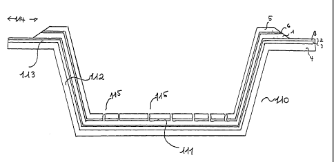
With reference to Figures 1 and 2, that illustrate two different embodiments
of the
receptacle according to the present invention in the tray-shaped
configuration, the tray 110 (or
120) has a bottom or base portion 111 (or 121 ) that may be flat or concave or
convex or of any
other shape, side walls 112 (or 122) and an outwardly directed flange 113 (or
123), which
extends around the rim or periphery of the tray. The mufti-layer structure
illustrated in these
Figures comprises a liquid absorbent layer 1, a distribution layer 6, a food-
contact layer 5
(both these latter layers are illustrated in the Figures as being perforated
by perforations 115
(or 125); said layers however could alternatively be imperforated but liquid
pervious), a
17
CA 02452584 2003-12-31
WO 03/006337 PCT/EP02/07464
liquid- and gas-barrier thermoplastic film 2 comprising a gas-barrier layer 3
and a heat-
sealable layer 8, and a separate support layer 4.
Either during or after the forming step, the flange of the container is carved
by removing
the absorbent layer 1 as well as the food-contact layer 5 and the distribution
layer 6, on top of
the absorbent one, and possibly part of the thermoplastic film 2 to expose
along a closed line
114 (or 124) in the circumferential flange, the heat-sealable layer 8 of the
liquid- and gas-
barrier film 2.
As illustrated in Figure 1 the absorbing layer is removed along the outward
circumferential
part of the flange for a width sufficient to guarantee a hermetic sealing of
the thermoplastic lid
thereto. Alternatively as illustrated in Figure 2 said carving is carried out
in an internal part of
the flange thus creating a track of a width sufficient for sealing the lid
thereto.
Removal can be obtained by cutting through the absorbing layer 1, any upper
layer 5 and 6,
and any layer in-between the absorbing layer 1 and the heat-sealable layer 8,
to reach the heat-
sealable layer 8 and then tearing horizontally to remove the uppermost layers
in the outward
circumferential part of the flange. The cut can be made in a direction
substantially
perpendicular to the flange or at an oblique angle relative to the plane of
the flange, wherein
angles of between 30° and 90 ° would be suitable. This step can
be carried out either on the
finished trimmed out containers or, preferably, after the thermoforming step
but before
trimming out the molded parts, so that a skeleton of the upper layers,
including the liquid
absorption layer 1, and the food contact layer 5 and distribution layer 6, if
present, is removed
altogether. The molded parts are then suitably trimmed out to get the final
receptacles with the
outward circumferential part of the flange made up of the lower layers only.
If it is desired to create a track in the flange then two different cuts
should be made therein
and only the portion between these two cuts will be removed.
In both cases the cuts can be made by any conventional means, including
blades, hot
knives/wires, laser etc.
To facilitate removal of the upper layers as desired to expose the heat-
sealable layer 8 of
the liquid- and gas-barrier thermoplastic film 2, it would be highly
preferable to take
18
CA 02452584 2003-12-31
WO 03/006337 PCT/EP02/07464
advantage of anyone of the various mechanisms known and used in the art for
separating two
films or layers, e.g. using a heat-sealable layer 8 that has a very low bond
with the adjacent
layer, i.e. the liquid absorbing layer 1 or any additional intermediate layer
11 positioned
between these two layers (a bond much lower than the bond between any other
two adjacent
layers in the structure) or using a heat-sealable layer 8 that is made of a
blend of materials
with a very low internal cohesion so that the separation occurs through the
thickness of layer 8
via a mechanism of cohesive failure.
In the former case the rupture of the upper layers of the laminate is followed
by the peeling
off of the upper layers from the heat-sealable layer 8. In this case it is
necessary to suitably
select the materials employed for both the heat-sealing layer 8 and the
adjacent layer, be it the
liquid absorbing layer 1 or a possible additional layer 11, and the
manufacturing process in
order to get a low bond between said two layers. Typically this is achieved by
selecting
polymeric materials having a great chemical dissimilarity and using processes
other than co-
extrusion for bonding said two layers.
In the latter case the rupture of the upper layers of the laminate is followed
by the internal
rupture of the heat-sealing layer 8 along a plane parallel to the layer
itself. Examples of blends
of materials that are only partially compatible and that consequently can fail
when a
transversal force is applied thereto are for instance blends of an ionomer
having a melt flow
index of less than 5 g/10 min and a modified ethylene/vinyl acetate copolymer
having a
substantially higher melt flow index, whereby the melt flow indices of the two
polymers in the
layer differ by at least 10, or blends of a copolymer of ethylene and acrylic
acid or methacrylic
acid, a modified EVA copolymer, and a polybutylene.
Examples of laminates suitable for the manufacture of a receptacle according
to the present
invention based on the above mechanisms are specifically illustrated in
Figures 7, 8 and 9.
More particularly said Figures illustrate preferred embodiments of the
receptacle according to
the invention.
Figure 7 illustrates a laminate where the bond between the heat-sealing layer
8 and the
adjacent liquid absorbing layer 1 is sufficiently low to allow peeling off of
the cut portion. In
19
CA 02452584 2003-12-31
WO 03/006337 PCT/EP02/07464
said preferred embodiment the structural layer 4 is a foamed polystyrene
layer, either open-
cell or, preferably, closed-cell; the liquid- and gas-barrier thermoplastic
film 2 comprises a
core gas-barrier layer 3 comprising an ethylene-vinyl alcohol copolymer, two
tie layers 10
comprising a carboxy or anhydride modified polyolefin, and a heat-sealing
layer 8 comprising
S a polyethylene or an ethylene-a-olefin copolymer; the liquid absorbing layer
1 is of open-cell
foam polystyrene; and the perforated food contact layer 5 is of non foamed
polystyrene. The
bond at the interface between the liquid absorbing layer 1 and the heat-
sealing layer 8 is very
low and once the cut in the thickness of the upper layers reaches said heat-
sealing layer 8, the
horizontal tearing will expose the heat-sealing layer 8. The arrow indicates
the rupture line.
Figure 8 on the other hand illustrates the case where the heat-sealing layer
8, that in the
embodiment illustrated in said Figure is not the outer layer of the liquid-
and gas-barrier
thermoplastic film 2, breaks by cohesive failure and allows removal of the
upper layers in the
receptacle flange. More particularly in said preferred embodiment the
structural layer 4 is a
foamed polystyrene layer, either open-cell or, preferably, closed-cell; the
liquid- and gas-
1 S barrier thermoplastic film 2 comprises a core gas-barrier layer 3
comprising an ethylene-vinyl
alcohol copolymer, two tie layers 10 comprising a carboxy or anhydride
modified polyolefin,
a heat-sealing layer 8 comprising a blend of an ionomer having a melt flow
index of about
1.25 g/10 min and a modified ethylene/vinyl acetate copolymer having a melt
flow index of
about 25 g/10 min, and a layer 9 comprising a resin such as styrene-butadiene-
styrene
copolymer, polystyrene, or ethylene-vinyl acetate copolymer; the liquid
absorbing layer 1 is of
open-cell foamed polystyrene; and the perforated food contact layer S is of
non foamed
polystyrene. Owing to the poor compatibility between the blend components of
the heat-
sealing layer 8, once the cut in the thickness of the upper layers reaches
said heat-sealing layer
8, the rupture will occur transversely as indicated by the arrow through the
thickness of said
heat-sealing layer 8.
Figure 9 illustrates another embodiment of a laminate where the bond between
the heat-
sealing layer 8 and the adjacent intermediate layer 11 is sufficiently low to
allow peeling off
of the cut portion. In said preferred embodiment the structural layer 4 is a
foamed polystyrene
CA 02452584 2003-12-31
WO 03/006337 PCT/EP02/07464
layer, either open-cell or, preferably, closed-cell; the liquid- and gas-
barrier thermoplastic film
2 comprises a core gas-barrier layer 3 comprising an ethylene-vinyl alcohol
copolymer, two tie
layers 10 comprising a carboxy or anhydride modified polyolefin, and a heat-
sealing layer 8
comprising a polyethylene or an ethylene-a-olefin copolymer; the liquid
absorbing layer 1 is
S of open-cell foam polystyrene; the perforated food contact layer 5 is of non
foamed
polystyrene; the intermediate layer 11, having a low bond with the heat-seal
layer 8, is of
styrene-butadiene-styrene copolymer and a closed-cell polystyrene foam layer
12 is positioned
between the liquid absorbing layer 1 and the intermediate layer 11. The bond
at the interface
between the intermediate layerl l and the heat-sealing layer 8 is very low and
once the cut in
the thickness of the upper layers reaches said heat-sealing layer 8, the
horizontal tearing will
expose the heat-sealing layer 8. The arrow indicates the rupture line.
Alternatively the receptacle according to the present invention can be
manufactured by
shaping as desired a first laminate comprising the liquid absorbing layer 1
and any upper layer
but not the liquid- and gas-barrier thermoplastic film and any lower layer,
and then coupling
said laminate with a laminate of a larger size, comprising said lower layers
only. In case of a
dish-shape receptacle this can be easily achieved by cutting the two partial
laminates in such a
way that the laminate comprising the liquid- and gas-barrier thermoplastic
film has the same
shape but is larger in size with respect to the laminate comprising the liquid
absorbing layer
and combining the two laminates by heat or glue lamination. When the
receptacle is tray-
shaped, this may be achieved by a vacuum skin lining process carried out with
the liquid- and
gas-barrier thermoplastic film on the lower surface of the tray-shaped
laminate comprising the
liquid absorbing layer or by thermoforming the lower layers of a size slightly
larger than the
upper layers and with a larger flange and then combining the two tray-shaped
parts into a
single tray.
A further specific object of the invention is the use of a receptacle
according to the present
invention in the packaging of a food product in a modified atmosphere wherein
the food
product is loaded onto or into a self absorbing gas-barrier receptacle
according to the present
invention, modified atmosphere is introduced into the package by gas flushing,
with or
21
CA 02452584 2003-12-31
WO 03/006337 PCT/EP02/07464
without prior vacuumization, followed by the sealing of a gas-barrier film or
lid along a
sealing line in the flange of the receptacle where the exposed surface is that
of the heat-sealing
layer 8 of the liquid- and gas-barrier thermoplastic film 2 to provide for a
hermetically closed
modified atmosphere package.
Examples of packages are illustrated in Figures 5 and 6 where Figure 5 refers
to a package
where the product 151 is placed into a tray-shaped receptacle 110 (as
illustrated in Figure 1)
and the package is then closed by sealing a gas-barrier lid 151 to the exposed
surface of the
heat-sealing layer 8 along a closed line 152 in the tray flange. The lid can
be a flexible, semi-
rigid or rigid film or sheet. It can be stretchable or non stretchable,
oriented or non-oriented
and if oriented it can be heat-shrinkable or heat-set. Also the gas-barrier
lid 151 may be a
monolayer or a multi-layer structure provided it is endowed with gas-barrier
properties.
Preferably however it will be a multilayer structure comprising at least a gas-
barrier layer and
a heat-sealable layer to create with the exposed surface of the heat-sealable
layer 8 of the
receptacle a hermetic seal.
Figure 6 shows a flat support 130, as illustrated in Figure 3, with a product
160 loaded
thereon and a flexible, oriented or non oriented, heat-shrinkable or non heat-
shrinkable,
stretchable or non stretchable gas-barrier lid 161 sealed to the exposed
surface of the heat-
sealable layer 8 of the liquid- and gas-barrier thermoplastic film 2 along the
closed line 162 at
the circumferential flange.
22