Note: Descriptions are shown in the official language in which they were submitted.
CA 02452747 2003-12-31
WO 03/005202 PCT/US02/21439
METHOD AND SYSTEM FOR PROVIDING A VIRTUAL USER INTERFACE
Cross-Reference to Related Auplications
This application claims priority to U.S. Provisional Application Serial Number
60/303,448, filed July 6, 2001, the entirety of which is hereby incorporated
by reference.
Technical Field
The present application generally relates to information and data management
systems
and methods. The present application more specifically relates to Information
Techonology
monitoring.
Background
Many information and service providers enable users to access information and
services via a client-server architecture, for example using web-based
applications written in
languages such as Java. Many of the functions performed by such applications
are routine
functions that a user may periodically request, such as checking a balance of
a checking
account or making a minimum payment to a credit card account, for example.
Presently, each time that a user wishes to perform one of these routine
functions, the
user must request the function to be performed and provide all of the input
for the function to
be performed. This is true even in cases where the input is standardized and
does not vary
from request to request.
Repeatedly requesting the same information from the user to accomplish a
previously
requested function is an inefficient use of the user's time. Some web-based
applications have
addressed this inefficiency by providing a capability to store user
preferences. Such
functionality, however, is only available sporadically, for specific web
applications, namely,
those applications which have been designed to include a feature of storing
and recalling user
preferences.
Consequently, a need exists for a system and method for reducing the amount of
time
and effort a user must provide to submit routine, periodic requests for
information or services.
Further, a need exists for a solution which is compatible with existing client-
server
applications.
1
CA 02452747 2003-12-31
WO 03/005202 PCT/US02/21439
Summary
The following presents a simplified summary of methods, systems, and computer
readable media associated with recording and replaying interaction associated
with a client-
server application, thereby providing a virtual user interface. This summary
is not an
extensive overview and is not intended to identify key or critical elements of
the methods,
systems, and/or media or to delineate the scope of the methods, systems, and
media. It
conceptually identifies the methods, systems, and media in a simplified form
as a prelude to
the more detailed description that is presented later.
This disclosure provides methods and systems for monitoring interaction
associated
with a client server application in a computer processing environment.
According to one
aspect of the disclosure, a method for monitoring interaction associated with
a client-server
application is disclosed. The method includes configuring recording, playback
and analysis
parameters. The method also includes recording control flow and server
responses associated
with the application. The method further includes replaying the control flow,
and comparing
responses received from the server to the replayed control flow to recorded
server responses
to determine whether an alert condition exists. The alert condition is
processed according to
the configured analysis parameters.
A system for monitoring interaction associated with an application is also
disclosed.
In one embodiment, the system includes a configuration module for defining and
storing
configuration data. The system also includes a recording module for monitoring
client-server
interaction of the application. The recording module is further operative to
store control flow
data representing the monitored client-server interaction. The system further
includes a
playback module. The playback module is operative to replay client portions of
the stored
control flow data and to analyze server responses to determine and report an
alert. In
addition, the system includes a control module for controlling the
configuration module, the
recording module and the playback module.
Computer-readable storage media are also disclosed which include processing
instructions for implementing certain disclosed methods.
Certain illustrative aspects of the methods, systems, and computer readable
media are
described herein in connection with the following description and the annexed
drawings.
These aspects are indicative, however, of but a few of the various ways in
which the
principles of the methods, systems, and media may be employed and thus the
examples are
intended to include such aspects and equivalents. Other advantages and novel
features may
become apparent from the following detailed description when considered in
conjunction
2
CA 02452747 2003-12-31
WO 03/005202 PCT/US02/21439
with the drawings.
Brief Description of the Drawings
For a more complete understanding of the present methods and systems,
reference is
now made to the following description taken in conjunction with the
accompanying drawings
in which like reference numbers indicate like features and wherein:
Figure 1 is a schematic block diagram of an example interaction recording
system;
Figure 2 is a flow chart that illustrates an example methodology for employing
the
interaction recording system of Figure 1;
l0 Figure 3 is an initial window of an exemplary embodiment the present
application;
Figure 4 is a "New hlstance" window of the exemplary embodiment the present
application;
Figure 5 is a control flow recording window of the exemplary embodiment the
present
application;
Figures 6A-6G are various windows presented according to a step-adding wizard
for
the exemplary embodiment the present application; and
Figures 7A-7D are various windows enabling method validation configuration for
the
exemplary embodiment the present application.
Detailed Description
Example methods, systems, and computer readable media are now described with
reference to the drawings, where like reference numerals are used to refer to
like elements
throughout. In the following description, for purposes of explanation,
numerous specific
details are set forth in order to facilitate thoroughly understanding the
methods and systems.
It may be evident, however, that the methods and systems can be practiced
without these
specific details. In other instances, well-known structures and devices are
shown in block
diagram form in order to simplify the description.
The present application augments traditional Information Technology management
solutions by providing the ability to record, replay and analyze interaction
between a user and
an application. In one embodiment, such interaction may represent business
logic occurring
within a client-server application. Although the exemplary system is described
with respect
to a client-server architecture, other architectures may be utilized, such as
a peer to peer
architecture, for example.
The present application describes an exemplary client-server interaction
3
CA 02452747 2003-12-31
WO 03/005202 PCT/US02/21439
recorder/player ("Interaction Recorder") which employs a user-friendly wizard-
based
interface to create a virtual user. The exemplary Interaction Recorder uses
the virtual user to
simulate a human user interacting with Enterprise Java Beans ("EJB's"). One or
more virtual
users then interact periodically with an associated client-server application
to analyze
whether the interaction or business logic is performing according to
specification. The
analysis is described as being performed at 3 levels: application response
time, returned
values, and exceptions, but analysis at other levels are possible.
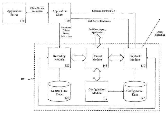
Referring to Figure 1, there is illustrated an example interaction recording
system 100
for monitoring, recording replaying and analyzing interactions between
application client 110
l0 and application server 115. The example interaction recording system 100
enables an end
user or application to capture and replay interaction of an EJB client with an
EJB server. The
captured interaction or control flow is stored as data in store 120. The
recording module 125
monitors and records the data provided by the application client 110 as well
as data returned
by application server 115 as control flow data. Playback module 130 enables an
end user,
application or intelligent agent to replay a control flow using the stored
control flow data
associated with the application client 110. During the process of replaying of
a control flow,
the responses from application server 115 are compared to the stored control
flow data
representing the responses originally provided by application server 115. If
the stored
responses are not consistent with the responses provided during the replayed
control flow,
playback module 130 reports an alert.
While providing other functionality, configuration module 135 enables the end
user to
customize the operation of the playback module 130. Configuration parameters
determined
by the end user are stored as configuration data in store 140 and include, for
example, alert
ranges and notification messae contents. Control module 145 enables an
intelligent agent,
end user or application to interact with the system 100 and controls the
recording, playback
and configuration modules.
To illustrate the utility of interaction recording system 100, consider an
exemplary
bank account EJB application that provides deposit, withdraw and check balance
methods. A
typical user interface, built using servlets, may use such methods to provide
au ATM-like
functionality through a standard web browser. Using the exemplary EJB
application, a
customer may deposit money, withdraw money and at times check the balance of
the user's
account. The recording module 125 can be used to record this interaction
either through the
web browser or directly with the EJBs.
Intelligent agents may invoke the playback module 130 to replay the recorded
control
4
CA 02452747 2003-12-31
WO 03/005202 PCT/US02/21439
flow data after a specific time interval. During playback, the playback module
130 may
determine that the balance check method is returning an unexpected value. This
non-
conformity could result in an immediate alert message being sent to the
administrator who
can then check the server and or the database to see why the error occurred
and take steps to
correct the problem.
In one embodiment, the control module employs a simple user interface that
provides
wizard-based paradigms to capture the client interaction and server responses.
The interface
enables the end user to direct the recording of user interactions and the
replaying of a
recorded control flow from store 120. The interface may simulate the user's
actions by
repeating the control flow steps in the exact sequence originally monitored.
The interface
may further report the results of the server's responses and the originally
recorded data.
Figure 2 illustrates one example methodology 200 that may be employed using
the
interaction recording system 100 of Figure 1. At block 210, the end user
configures the
interaction recording system 100. Configuring the interaction recording system
100 may
include, for example, defining a playback interval, defining alert conditions,
and defining
actions for responding to detected alert conditions.
The recording module 125 is employed at block 215 to monitor and record the
control
flow of a client-server application session. The monitored control flow
includes the
interaction between the client 110 and the server 115, and is stored.as
control flow data in
store 110. At a predetermined playback interval, the playback module 130 is
employed at
block 220 to replay the control flow of the recorded session. The playback
module 130
compares the responses to the replayed control data received from application
server 115 to
the responses stored in control flow data store 120 to determine at block 230
whether an alert
condition has occurred. If an alert condition is detected, the alert condition
is processed at
block 235, otherwise the methodology ends.
Referring now to Figures 3-7D, there are illustrated various example windows
which
may be presented to the user by the interaction recording system 100 to effect
the methods
and operate the systems of the present application. The exemplary system is an
application
designed to be executed on the BEA WebLogic PlatformTM provided by BEA
Systems, Inc.
Figure 3 illustrates an initial window 300 which enables the user to select
expert agents. W
order to begin recording a new control flow, the user selects "Instances" from
the "WebLogic
Business Logic Expert Agent" tree. Alternatively, the user may select
"Instances" from the
"Tools" menu. Selection of "Instances" enables the user to add, delete or edit
stored control
flow instances. Selecting "Add" enables the user to begin recording a new
control flow.
s
CA 02452747 2003-12-31
WO 03/005202 PCT/US02/21439
Figure 4 depicts a "New Instance" window 400 which enables the user to define
certain characteristics of the control flow to be recorded. Specifically, the
user may define
the name under which the control flow will be stored for future reference. The
user may also
provide a textual description of the control flow. In the illustrated
embodiment, the server
name may be selected from the WebLogic EJB servers previously configured in a
database
under the WebLogic Server Expert Agent. The server connection parameters, such
as the
URL, user name, and password axe populated based on the WebLogic Server Expert
Agent.
Once the characteristics of the new control flow have been defined, the user
may
select "Launch Recorder" to begin recording the control flow of an application
session. The
selection of "Launch Recorder" directs recording module 125 to establish a
connection with
the WebLogic EJB server and display the control flow recording window 500
depicted in
Figure 5.
The example control flow recording window employs a familiar document
processing
interface design augmented with additional EJB-specific options. The interface
has the
following menu options:
File: This option is used to access file handling functions.
New: This option prompts the recording module to open a new control flow.
If at the time another control flow is active, the user is prompted if the
control flow should be saved or not.
Open: This option prompts the playback module to open a prerecorded
control flow.
Save: This option saves the currently active control flow under its current
name.
Save as: Tlus option saves the currently active control flow under a different
name.
Exit: This option closes the interaction recording system.
Connect: This option is used to connect to the WebLogic EJB server.
Connect to server: This option prompts user for the server connection
parameters.
Record: This option allows user to add new steps to the currently active
control flow.
Start Recording: This option initializes the control flow recording and is
used to
begin recording.
Add new step: This option starts the wizard that adds a new step at the end of
the active control flow.
Play: This option is used to access functions that play all or part of a
prerecorded control
6
CA 02452747 2003-12-31
WO 03/005202 PCT/US02/21439
flow.
Play Recording: This option plays the currently active control flow from
beginning to end.
Play Step: This option plays only the next step in the currently active
control flow.
Each recorded control flow may be made up of one or more individual steps, or
portions of a session. Refernng now to Figures 6A-6G, there are illustrated
the windows
presented by the recording module when adding a single step to a control flow.
The
successive windows are presented in a "wizard" format that assists the user to
record single
step of a control flow. In each window, the user enters data and selects
"Next" button 614 in
order to proceed, "Back" button 613 to edit previously entered selections or
"Cancel" button
615 to terminate the wizard.
Figure 6A depicts a window 610 that allows the user to define a name 611
associated
with the step to be recorded. The user may also provide a textual description
612 of the step.
Figure 6B depicts a window 620 that presents user with the available EJB's in
the
server associated with the control flow. The user may select an unused EJB
from selection
window 621 or any EJB already in use in the control flow from selection window
622. Any
EJB's already in use in the control flow are presented as 'Cached Beans' in
selection window
622.
Figure 6C depicts a window 630 that enables the user to select the EJB method
to be
' used to create and/or find Java Bean instances. The user selects an EJB
method from
selection window 631.
Figure 6D depicts a window 640 that enables the user to define which
parameters
from window 645 are to be used by the create method, if any. The Java type of
each
parameter is displayed for informational purposes.
Figure 6E depicts a window 650 that enables the user to select a method to
execute
from drop-down selection menu 655.
Figure 6F depicts a window 640 that enables the user to assign values to the
parameters defined in window 640. The values are assigned using input window
666.
Figure 6G depicts a window 670 that displays the execution results of the
method
previously defined by the user using windows 620, 630, 640 650 and 660. Window
670 also
enables the user to define validation tests for the method results. The user
selects
"Validate..." button 675 to define the validation tests, "Finish" button 677
to complete the
CA 02452747 2003-12-31
WO 03/005202 PCT/US02/21439
addition of the step to the control flow, "Back" button 613 to edit previously
entered
selections or "Cancel" button 615 to abort the addition of the step.
Referring now to Figures 7A-7D, if the user elects to define validation tests,
the
configuration module provides a series of windows to enable the user to define
how the
method results are validated. These windows enable the user to define
validation based on
three factors: 1) the actual return value of the method, if any; 2) the time
taken to execute the
method and 3) the exception raised by the method, if any. The validation can
include a
number of tests for each of the three factors.
Figure 7A depicts validation window 700 having the "Result" tab 707 selected,
l0 enabling the user to define the validation of the result of the method. The
example system
supports return values of various types, including for example, strings,
integer numbers and
double integer numbers. When validating strings, the system compares a pre-
defined pattern
against a returned string value. When validating numbers, the system compares
a pre-defined
range of values against a returned numeric value.
Window 700 illustrated the validation definition for a double integer numeric
value.
In the illustrated example, a lower and upper limit to the overall validation
range may be
defined, as well as five categories within the range. Each category may be
configured to
provide a different alert message.
Each category has an associated "Details" button, such as button 702, which
may be
selected to define certain cause, meaning, action and notification parameters
associated with
the category. When the results fall within a particular category range, the
associated
parameters determine what notification, if any, to provide.
Figure 7B depicts an example "Critical Details" window 720 which is presented
if the
user selects button 702 for the "Critical" range from window 700. When the
returned result
of a method parameter falls within the pre-defined critical range, the
playback module refers
to these parameters to determine any action to take. If the notification
parameter 722 is
selected, an alert notification will be delivered to a notification
recipient's e-mail address or
pager. The notification path is pre-defined and configured using the
configuration module.
The cause 724, meaning 726 and action 728 of the critical alert is
incorporated into the alert
message.
Figure 7C depicts validation window 700 having the "Performance" tab 708
selected,
enabling the user to define the validation of the performance of the method.
The execution
time observed during recording may be used as a benchmark to define an
alarming level of
performance. Specifically, if the execution of the method takes unexpectedly
long, the
s
CA 02452747 2003-12-31
WO 03/005202 PCT/US02/21439
administrators may need to be notified. The "Performance" tab 708 enables the
user to define
different levels of performance.
When validating performance, the system compares the access time for
processing a
method with the limits defined by the user using the "Performance" tab 708 of
window 700.
Like the "Result" tab 707, the "Performance" tab 708 enables the user to
define an upper and
lower limit to the range of access times, as well as five categories within
the range. Each
category has an associated "Details" button which enables the user to define
any action that
may be desired for the category.
Figure 7D depicts validation window 700 having the "Exception" tab 709
selected,
enabling the user to define the validation in the event an exception occurs
during the
processing of the method. Generally, exceptions indicate errors. Depending on
the recording
control flow, however, an exception may be expected. The exception validation
can be used
configure the status of the control flow based on the exception message. The
configuration is
similar to the string return value validation.
What has been described above includes several examples. It is, of course, not
possible to describe every conceivable combination of components or
methodologies for
purposes of describing the systems, methods, and computer readable media
associated with
business process policy data. However, one of ordinary skill in the art may
recognize that
further combinations and permutations are possible. Accordingly, this
application is intended
to embrace such alterations, modifications, and variations that fall within
the scope of the
appended claims. Furthermore, to the extent that the term "includes" is
employed in the
detailed description or the claims, such term is intended to be inclusive in a
manner similar to
the term "comprising" as that term is interpreted when employed as a
transitional word in a
claim.
9