Note: Descriptions are shown in the official language in which they were submitted.
CA 02453210 2004-O1-05
WO 03/003948 PCT/US02/21774
ANTI-ARRHYTHMIA DEVICES AND METHODS OF USE
CROSS REFERENCE TO RELATED APPLICATIONS
The present application claims priority to U.S. Provisional Patent Application
No. 60/303,573, filed July 6, 2001, whose contents are fully incorporated
herein by
reference.
BACKGROUND OF THE INVENTION
Cardiac arrhythmia affects millions of people worldwide and is broadly defined
as an abnormal or irregular heartbeat that may involve changes in heart
rhythm,
producing an uneven heartbeat, or heart rates, causing a very slow or very
fast
heartbeat. Common types of arrhythmias, explained in further detail below,
include
bradyarrhythmias and tachyarrhythmias, both being typically ventricular or
supraventricular in origin.
Bradyarrhythmias are slow heart rhythms (e.g., less than 60 beats per minute)
that may result from a diseased or failing sinoatrial (SA) node,
atrioventricular (AV)
node, HIS-Purkinje, or bundle branch system, as explained in further detail
below.
Ventricular arrhythmias are arrhythmias that begin in the lower chambers of
the heart.
In contrast, supraventricular arrhythmias are arrhythmias that originate above
the
ventricles of the heart, such as the upper chambers (i.e., atria) or the
middle region
(e.g., AV node or the beginning of the HIS-Purkinje system). Ventricular and
supraventricular arrhythmias are generally characterized by accelerated rates
(e.g.,
more than 100 beats per minute) that exceed what is considered normal
heartbeat
rhythms (e.g., between 60 and 100 beats per minute).
The most common type of supraventricular arrhythmia is atrial fibrillation,
with
incidence of more than a quarter-million cases each year in the U.S. alone,
and a
prevalence of nearly 2.0 per 1000 US patient-years. To better understand the
mechanism and characteristics of atrial fibrillation, a general understanding
of the
mechanical and electrical activity of the heart is helpful. For this purpose,
attention is
directed to Figure 1.
Figure 1 depicts a cross-sectional diagram of a normal, healthy heart 10. The
heart 10 is a four-chamber, double-sided pump made of muscle tissue that
contracts
when subjected to electrical stimulation. The electrical stimulation that
produces a
1
CA 02453210 2004-O1-05
WO 03/003948 PCT/US02/21774
heartbeat originates in the SA node 12, located at the junction of the
superior vena
cava 14 with the right atrium 16, and spreads radially through the atria
causing the
muscle of the heart's upper chambers to contract and pump blood to the
ventricles.
From the atria, the electrical signal then converges on the AV node 18,
located in the
right posterior portion of the interatrial septum. The impulse from the AV
node 18 then
passes to the bundle of HIS 20, which branches at the top of the
interventricular
septum 22 and runs subendocardially down either side of the septum, and
travels
through the bundle branches 24. The signal then passes to the Purkinje system
26
and finally to the ventricular muscle causing the lower chambers of the heart
to
contract and pump blood to the lungs and the rest of the body. After
contraction of the
lower chambers, the sinus node initiates the next rhythm or heart beat and the
entire
cycle is repeated. In general, it is rate of discharge from the SA node 12
(also referred
to as the normal cardiac pacemaker) that determines the rate at which the
heart 10
beats.
This synchrony of contraction between the atria and ventricles produces a
normal heartbeat. In its broadest sense, atrial fibrillation (AF) represents a
loss of
synchrony whereby the atria quiver (beating at a rate of about 600 beats per
minute)
instead of beating or contracting effectively. The loss of atrial contraction
and
conduction of electrical signals from the atria to the ventricles often cause
blood to
pool and clot in the atria, and especially in the atrial appendages. If the
clot becomes
dislodged from the atrium, it can travel through the bloodstream and create a
blockage
in a vessel that supplies blood to the brain, resulting in stroke. It is
estimated that
fifteen percent of all strokes occur in people with AF, which translates to
about 90,000
strokes each year in the United States alone.
Conventional therapy or treatment options for AF include medication, AF
suppression and surgery. Medication or drug therapy is generally the first
treatment
option employed to control the rate at which the upper and lower chambers of
the
heart beat. Conventional medications used to treat AF include beta-blockers,
such as
metoprolol or propanolol, and calcium-channel blockers, such as verapamil or
diltiazem, which depress conduction and prolong refractoriness in the AV node.
Other
medications such as amiodarone, ibutilide, dofetilide, propafenone,
flecainide,
procainamide, quinidine and sotalol are used to affect the electrophysiology
of the
heart to maintain normal sinus rhythm and can thereby terminate or, in some
cases,
prevent AF. Although anticoagulants or blood-thinners such as warfarin or
aspirin are
2
CA 02453210 2004-O1-05
WO 03/003948 PCT/US02/21774
not designed to treat AF, these medications are often used to reduce the risk
of clot
formation and stroke which, as previously discussed, often occur in patient's
suffering
from AF.
AF suppression, frequently a second treatment option for patients with AF, may
be accomplished using an implanted pacemaker to stimulate the heart in a way
that
preempts any irregular rhythms. In general, the pacemaker stimulates or
overdrives
the heart at a rate slightly higher than its normal, intrinsic rate.
Overdriving the heart
enables the device to control the heart rate and, thereby, suppress potential
episodes
of AF.
Another alternative treatment for AF is surgery. In general, an
electrophysiology study is first performed to characterize the arrhythmic
event. This
study usually includes mapping the exact locations of the electrical impulses
and
conduction pathways along the cardiac chambers using conventional mapping
techniques. After locating the cardiac tissue that is causing the arrhythmia,
the tissue
is then surgically altered or removed to prevent conduction of aberrant
electrical
impulses in the heart. One example of a surgical procedure used to treat
cardiac
arrhythmias is the Maze procedure.
The Maze procedure is an open-heart or percutaneous surgical procedure
designed to interrupt the electrical patterns or conduction pathways
responsible for
cardiac arrhythmia. Originally developed by Dr. James L. Cox, the Maze
procedure
involves carefully forming a "maze" of surgical incisions (from which the
procedure's
name is derived) in both atria to prevent the formation and conduction of
errant
electrical impulses, while still preserving the function of the atria. The
incisions
channel or direct the electrical impulses along the heart to maintain
synchrony of
contraction between the atria and ventricles of the heart, thereby producing a
normal
heartbeat. In addition, resulting scar tissue generated by the incisions also
prevents
formation and conduction of aberrant electrical signals that cause AF, thereby
eradicating the arrhythmia altogether.
Although surgical intervention, such as the Maze procedure, has proven
successful in treating AF, these procedures are highly invasive, generate many
post
operative complications, require lengthy patient recovery times and are quite
costly.
As a result, minimally invasive ablation techniques have become more popular
and
have been offered as an alternative treatment to surgical intervention for
patients
suffering from AF.
3
CA 02453210 2004-O1-05
WO 03/003948 PCT/US02/21774
Cardiac ablation techniques typically involve the removal or destruction of
cardiac tissue and the electrical pathways that cause the abnormal heart
rhythm. In
general, cardiac ablation is less costly, has fewer side effects and requires
less
recovery time for the patient compared to more invasive procedures. There are
various methods by which a cardiac ablation procedure may be performed. These
methods and energy modalities include cryoablation, radiofrequency (RF)
ablation,
laser ablation, microwave, vaporization, balloon ablation, drug elution and
photodynamic therapy.
During an ablation procedure, an electrophysiology study is first performed to
characterize the arrhythmic event and map the precise locations that exhibit
the
arrhythmia. Once these sites are identified, an ablation catheter is
maneuvered to
each of these sites and a sufficient amount of energy is delivered to ablate
the tissue.
As a result, the energy destroys the targeted tissue and, thus, makes it
incapable of
producing or conducting arrhythmia, while leaving the adjacent healthy tissue
intact
and functional.
In addition to ablating the specific arrhythmic tissue sites, alternative
ablation
procedures, such as cardiac segmentation procedures, have been developed to
mechanically isolate or re-direct errant electrical signals in the heart.
These
procedures typically involve forming one or more linear or curvilinear lesions
in the
wall tissue of the heart to segment the cardiac chambers, similar to the above-
described Maze procedure. These segmented lesions are generally formed in the
atrial tissue of the heart, although accessory pathways, such as those through
the wall
of an adjacent region along the coronary sinus, have also been produced.
Advances in mapping and characterizing cardiac arrhythmias, particularly AF,
have provided much insight into the mechanism of AF. Research has shown that
there are at least six different locations in the left and right atria of the
heart where
relatively large, circular waves of continuous electrical activity (i.e.,
macro reentrant
circuits) occur in patients suffering from AF. Recently, it has been
determined that
these reentrant circuits or wavelets may actually be confined to a limited
area near the
pulmonary veins. In other words, some forms of AF may even be triggered or
maintained by a single focus of automatic firing. As a result, several
procedures have
been developed whereby one or more ablation segments or lesions are formed in
tissue to isolate the pulmonary veins and thereby block the electrical
impulses that
cause AF.
4
CA 02453210 2004-O1-05
WO 03/003948 PCT/US02/21774
Although catheter based ablation procedures are less invasive than
conventional surgical procedures, there are various complications that may
occur.
Examples of possible complications include ablation injuries, bleeding,
hematoma,
pericardial effusion and cardiac tamponade, failure of the procedure, scar
formation
and stenosis. In addition, the time course of lesion maturation and scar
formation
following cardiac ablation procedures often result in delayed onset of
electrical
isolation and high incidence of post-operative atrial fibrillation.
In view of the above, there is a need for a minimally invasive device and more
effective and efficient methods to treat cardiac arrhythmias. In particular,
it is
desirable that the methods have a high success rate at treating arrhythmias,
have
minimal to no side-effects or related complications, and can be completed more
rapidly than conventional methods. In addition, the treatment methods should
also
reduce patient recovery times and hospital costs. Overall, the method of
treatment
should also improve the quality of life for patients.
BRIEF SUMMARY OF THE INVENTION
In general, the present invention contemplates an implantable device and
method for modifying conduction, electrical connection and propagation
properties in a
tissue and/or treating cardiac arrhythmias. The device comprises a structural
platform
made of a biocompatible material, wherein the platform may be conformable to a
shape of a target tissue site. In addition, the platform may also include a
treatment
component sized and shaped to induce a fibrotic response in the target tissue.
The
treatment component may also be configured to cause sufficient fibrotic
response so
as to substantially eliminate cardiac arrhythmias.
The present invention also contemplates a method of treating cardiac
arrhythmias. In general, the method comprises delivering a treatment device to
a
target site and manipulating the device to conform a shape of the device to a
shape of
the target site. The method may also include modifying a tissue makeup at the
target
site and allowing the modification of tissue makeup to proceed so as to induce
a
response that results in electrically decoupling the tissue. The method may
further
include leaving the treatment device implanted at the target site.
Additionally, the present invention contemplates a device for modifying tissue
at
a target tissue site of an organ, wherein the device comprises at least one
deployment
platform. The deployment platform may include a treatment component configured
to
5
CA 02453210 2004-O1-05
WO 03/003948 PCT/US02/21774
induce a material tissue response at the target tissue site. In addition, the
treatment
component may also be configured to induce a material tissue response
sufficient to
modify local physiologic properties of the organ so as to achieve a desired
therapeutic
goal for the organ.
The present invention also contemplates a method of inducing a material tissue
response at a target site, wherein the method includes delivering a treatment
device to
the target site and ensuring contact of a treatment component of the treatment
device
with tissue at the target site. The method may also include inducing the
material
tissue response at the target site as a result of ensuring contact of the
treatment
component with the tissue and allowing the material tissue response to
continue at the
target site at least until a therapeutic goal is substantially achieved.
BRIEF DESCRIPTION OF THE DRAWINGS
Other features and advantages of the present invention will be seen as the
following description of particular embodiments progresses in conjunction with
the
drawings, in which:
Figure 1 is a cross-sectional diagram of a normal, healthy heart;
Figure 2A illustrates another embodiment of the device in accordance with the
present invention;
Figures 2B and 2C are sectional views of other embodiments of an implanted
device in accordance with the present invention;
Figures 3A-3C illustrate sectional views of various embodiments of an
implanted device in accordance with the present invention;
Figure 4A illustrates the various layers of a vessel;
Figure 4B illustrates areas of high sheer at various tissue points in
accordance
with the present invention;
Figures 5A and 5B illustrate other embodiments of the device in accordance
with the present invention;
Figures 6A and 6B are sectional views of various embodiments of an implanted
device in accordance with the present invention;
Figure 7 is a perspective view of an embodiment of the device in accordance
with the present invention;
Figures 8A-8C illustrate perspective views of other embodiments of the device
in accordance with the present invention;
6
CA 02453210 2004-O1-05
WO 03/003948 PCT/US02/21774
Figures 8D and 8E illustrate sectional views of various embodiments of an
implanted device in accordance with the present invention;
Figures 9A and 9B illustrate perspective views of various embodiments of an
implanted device in accordance with the present invention;
Figures 10A and 10B illustrate perspective views of various embodiments of an
implanted device in accordance with the present invention;
Figure 11 illustrates a perspective view of a ring-shaped embodiment of the
device in accordance with the present invention;
Figures 12A-12C illustrate sectional views of various embodiments of an
implanted device in accordance with the present invention;
Figure 12D illustrates a perspective view of an embodiment of an implanted
device in accordance with the present invention;
Figure 12E illustrates a section view of an embodiment of a device implanted
on an internal surface of a vessel in accordance with the present invention;
Figure 12F illustrates a perspective view of an embodiment of a device
implanted on an external surface of a vessel in accordance with the present
invention;
and
Figure 12G illustrates a perspective view of an embodiment of an implanted
device in accordance with the present invention.
DETAILED DESCRIPTION OF THE INVENTION
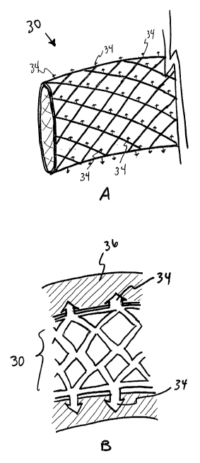
In one preferred embodiment of the invention, a stent-shaped device 30 may be
used to treat, prevent and/or terminate arrhythmias. It should be noted that
use of the
term "stent" is not meant to be limiting but, rather, is used for reader
convenience and
brevity. In general, the device 30 resembles an "inverse sock" fabricated from
a fine
netting material (e.g., Nitinol", spring-tempered stainless steel, cloth
fiber, etc.). The
netting material may be self-expandable, causing the device 30 to tightly
conform to
the structure into which it is placed. In one embodiment, a high spatial
frequency of
fine material (i.e., fine fibers, elongate elements (discussed in further
detail below) or
strands) is used to fabricate the device 30. This design provides the device
30 with
added axial conformability and trans-axial capabilities, resulting in improved
tissue
adhesion and fit.
The device or deployment platform 30 of the present invention may also be
characterized by its ability to bend longitudinally and trans-axially. This
capability
7
CA 02453210 2004-O1-05
WO 03/003948 PCT/US02/21774
enables the device 30 to conform to any desired. biologic shape, including,
but not
limited to, the wall of an artery, vein, cardiac chamber or other biologic
target
structure. In addition, the device 30 may also be characterized by its ability
to expand
in a radial direction, and continue to conform to a shape that may change. In
one
embodiment, the device 30 may have a maximum size, beyond which the device 30
does not expand. This configuration prevents the tissue structure 36, into
which the
device 30 is placed, from growing or expanding above a predetermined size.
As shown in Figure 2A, one or more hollow protrusions 34 (discussed in further
detail below) lie on an external surface of the device 30. Upon radial
expansion of the
device 30, via self-expansion, balloon expansion, or other means, the
protrusions 34
pierce or embed into the tissue 36 target site of the lumen, as illustrated in
Figure 2B.
The protrusions may penetrate the vessel wall either partially or completely
(as shown
in Figures 2B and 2C), gaining access to any cells at any location in or on
the
structure. The protrusions may also be solid rather than hollow, as may be
desirable if
drug delivery is not contemplated. In addition to anchoring the device 30, the
protrusions also serve various other functions as described in further detail
below.
In one embodiment, injection from a drug delivery balloon (not shown) causes
the hollow protrusions 34 to conduct the drug to the adventitial surface of
the lumen or
vessel. The drug may then cause cell death, fibrosis or inflammation, all of
which may
be used to combat arrhythmia depending on the type of drug used and desired
tissue
response.
As disclosed in further detail below, the device 30 of the present invention
and
its methods of use are designed to achieve a variety of therapeutic goals
including, but
not limited to, prevention, treatment and/or elimination of arrhythmias.
Studies have
shown that some forms of AF originate in the pulmonary veins 44 or coronary
sinus.
More specifically, it has been determined that sources of AF originate in
atria) tissue
that is on the surface or ingrown into the vessel as it enters the left atrium
(i.e., at or
near the ostium of the vessel entrance into the atrium). Although further
references
will be made specific to the pulmonary veins 44, it is understood that other
vessels
(e.g., coronary sinus, aorta, abdominal aorta, pulmonary artery, atrium,
cerebral
vessels, etc.) are also included within the scope of the present invention.
When positioned at this target site, the device 30, preferably in an expanded
state, eliminates or neutralizes the electrical activity and conductivity of
the atria) cells
on the pulmonary vein so that AF stimulation is either prevented (by ablating
the atria)
8
CA 02453210 2004-O1-05
WO 03/003948 PCT/US02/21774
cells) or the impulses are prevented from propagating into the atrium. In
principle, it is
distortion of the anatomy, such as the ostium, by a luminal or extra-luminal
device 30
that permits sclerosis, cell death, scar formation, mechanical injury,
laceration or any
combination of these results to attack impulse stimulation and conduction. The
following are but a few examples of atrial tissue ablation methods. It is
understood
that other tissue modification and ablation methods though not specifically
disclosed
herein are also included within the scope of the claimed invention.
In one embodiment, the device 30 (with or without grasping members, as
discussed in further detail below) is radially expanded, for example via self-
expansion
and/or balloon expansion, in the lumen or outside the lumen (e.g., on the
adventitia) of
the pulmonary vein 44. Alternatively, the device 30 may be expanded on an
endocardial 40 or epicardial 42 surface of the heart. Expanding the device 30
sufficiently beyond the normal diameter of the pulmonary vein 44 causes the
vessel to
severely stretch, which induces cellular changes that alter the biologic
behavior of the
tissue 36.
In particular, the fine network of blood vessels called the "vasa vasorum,"
which
are located on the outer surface of many blood vessels and supply the vessel
wall
itself with blood, are subsequently compressed by this over-stretching,
resulting in
fibrosis. This vessel over-stretch may further produce tissue/vessel ischemia
and
other tension effects that may also induce fibrosis. The fibrosis may be
induced by
many mechanisms including, but not limited to, growth factors (Hypoxia
Inducible
Factor-1 alpha (HIF-1alpha), Vascular Endothelial Growth Factor (VEGF), etc.)
and
cytokines.
Lack of blood to the atrial cells combined together with the fibrosis induced
by
the over-stretching renders the atrial cells inactive. However, any unaffected
cells
upstream from the over-stretched area can still produce the stimulatory
potentials.
While these cells may still produce a stimulus, it cannot be propagated
through the
fibrotic area in and/or on the vein due to the fibrosis electrically
decoupling the
affected cells.
Vessel over-stretch, or other mechanical tissue change, is accomplished
initially by deployment of the device 30. However, continued or chronic over-
stretch
may be achieved by simply maintaining the oversized device 30 within the
vessel. As
such, the over-stretch itself may also be enough to induce adventitial and/or
medial
fibrosis simply due to the stretch process.
9
CA 02453210 2004-O1-05
WO 03/003948 PCT/US02/21774
The purpose of the fibrosis induced by the device 30 may be several-fold. In
one embodiment, the fibrosis may serve to mechanically prevent organ or gross
body
expansion. For example, the structural component of the device 30 may be
tailored to
expand only to a certain degree. Fibrosis formed in the tissue 36 functions to
tightly
attach or "glue" the device 30 to the tissue. Moreover, the fibrosis serves to
anchor
the tissue of interest to the supporting structure/device 30, and even
integrate the
device completely into the tissue. As such, further expansion of the
biological
structure is prevented due to the mechanical properties of the device 30 and
due to
the fibrosis itself (which may develop and grow to contain collagen that will
further
inhibit mechanical expansion).
Alternatively, the fibrotic response from the expandable device 30 may enable
the tissue 36 to retain sufficient pliability to maintain normal tissue (or
body organ)
function, yet increase its overall structural strength. For example, fibrosis
may be
induced to strengthen the wall of a cardiac ventricle when the device 30 is
placed on
the inside of the chamber/structure, while still allowing the ventricle to
contract, move
and fulfill its normal function. However, the fibrosis also prevents
ventricular
expansion beyond a certain predetermined size. In general, the material make-
up of
this type of pliable fibrous tissue comprises more elastin and other pliable
materials
than collagen.
Alternatively, the fibrotic response may be stimulated to a severe degree
causing a process of negative remodeling or contraction. This response, well
known
by those skilled in the art, results in natural scar formation that promotes
wound
contraction or shrinkage. The amount of fibrosis contraction may be
controllable, via
device materials, structure and other components, and may range from no
remodeling
to a small/medium/large amount of negative remodeling (resulting in
contraction).
This would be of particular use in preventing expansion of an aneurysm, as in
the
abdominal aorta or the cerebral vessels. The degree of remodeling is based
upon the
pre-selected application and desired response.
In addition to device expansion, device materials and structure may also be
used to biologically guide the cellular and biologic features of the eventual
tissue
response and/or therapeutic goal. For example, the device 30 may be configured
to
induce elastance in the tissue or an elastin-rich fibrosis (e.g., stimulate
elastin
synthesis and cellular growth) that is quite flexible and visco-elastic.
Alternatively, the
device may be configured to stimulate growth of densely packed collagen that
may
CA 02453210 2004-O1-05
WO 03/003948 PCT/US02/21774
mimic the need for such bioabsorbable tissue 36. In the case of collagen, the
induced
tissue 36 is quite inelastic and, thus, prevents tissue and device expansion.
As such,
inducing a simultaneous combination of elastin and collagen may simulate any
range
of mechanical properties for both tissue 36 and device 30.
In an alternate embodiment, the device 30 may be configured to control the
biologic features of the fibrosis and its cellularity. For example, a highly
cellular scar
may be formed or, alternatively, less cellular tissue may be produced due to
device
structure and/or materials. In another embodiment of the invention, the device
30 may
be coated with a material to stimulate less collagen or elastin growth and
increased
glycose-amino-glycan and other components of extra cellular matrix production.
There are,numerous additional methods by which to induce fibrosis, thereby
preventing aberrant impulse conduction through tissue 36. In addition to over-
stretch
injury, inflammation and toxicity may also be used, as discussed further
below.
Inflammation induced fibrosis may be accomplished using an embodiment of
the device 30 having prongs or tissue grabbers 34 that penetrate partially
into or
completely through the vessel. A chemical irritant located on the surface of
the prongs
34 causes the desired inflammation and, thereby, induces fibrosis in the
atrial tissue
36. In general, the fibrosis occurs in and around the three-dimensional
structure and,
thus, it is the structural configuration of the device 30 that
guides/determines the
eventual fibrosis configuration. As discussed in further detail below, the
device 30
may be configured in any arbitrary shape, size and density and may include one
or
more of a variety of chemicals/agents/substances. Alternatively, the device 30
may be
placed only against the interior surface and tissue ablation may still occur
on the outer
surface of the biologic structure.
In an alternate embodiment, only the tips of the prongs 34 are coated with a
chemical irritant, the remainder of the stalk of each prong 34 being uncoated
and,
thus, inactive. Further, the interior of the prongs 34 may house additional
chemical
irritant that elutes out into the outer regions of the vein, thereby gradually
inducing a
fibrotic response that prevents initiation or propagation of the arrhythmia.
Examples of
such chemical irritants include, but are not limited to, metallic copper,
zinc, talc,
polymers, drug-eluting polymers, tetracycline or other fibrosis-inducing
substances:
In another embodiment of the invention, a toxic substance may also be used to
induce fibrosis. The substance is released into the tissue 36 by the device
30, via a
delivery device and/or any of the previously disclosed methods, and either
kills atrial
11
CA 02453210 2004-O1-05
WO 03/003948 PCT/US02/21774
cells or prevents their depolarization and/or conduction. Thus, the resulting
fibrosis or
scarring inhibits cell stimulation and/or impulse propagation and, thereby,
prevents or
terminates the arrhythmia. Examples of toxic substances include, but are not
limited
to, metallic copper, zinc, polymers, poly-lactic acid, poly-glycolic acid,
tetracycline, talc
or any other chemicals/agents/substances capable of fibrosis induction.
Use of a conventional stent-shaped device 30 near the atrial entrance of the
pulmonary vein 44, or entrance of any other vessel, generally distorts the
ostium-atrial
entrance geometry in a radial (i.e., outward, trans-axial) direction. As
previously
discussed, this configuration may be effective in attacking arrhythmias since
cell/tissue
death or fibrosis may successfully interrupt the conduction/stimulation of AF.
In some
instances, there may be cells extending up and down the ostial wall that may
escape
the fibrotic process. In such an instance, a flared device may be used.
Referring to Figures 3A and 3B, an alternate embodiment of the device 30 of
the present invention includes one or more outwardly flared portions 46. When
positioned within a patient, the flared end 46 is located at or near the
ostium or vein
atrial interface. In addition to anchoring the device 30, this device
configuration also
draws tissue into the ostium and, in so doing, causes the cells to cease
conduction,
either by death or fibrosis. Inevitably, distortion of the ostium prevents
propagation or
conduction of impulses into the atrial tissue 36 and, thereby, terminates
arrhythmias.
This mechanical distortion of the tissue and/or ostium geometry, in effect,
brings the ostium into the lumen of the device 30. In other words, cells that
were
previously within the atrium at the ostial site are relocated within the new
lumen
created by the mechanical support of the device 30.
In another embodiment, illustrated in Figure 3C, the flared end 46 of the
device
30 may further include a lip or ring 48 that extends out into the atrium 50.
As such, the
ring 48 functions to prevent conduction and/or generation of impulses beyond
the
ostium and, in so doing, terminates AF or prevents its conduction into the
atrial tissue.
In general, the device 30 of the present invention functions to stretch not
only
the vein, but also the ostium. This stretch causes tension in the vessel wall
and
compression of blood supply in either capillary form or vasa vasorum. The
resulting
compression may further produce tissue ischemia and other tension effects and
induce fibrosis and/or collagen/matrix formation to interrupt electrical
impulse
generation and conduction. As disclosed in further detail below, toxic or
inflammatory
12
CA 02453210 2004-O1-05
WO 03/003948 PCT/US02/21774
agents may also be included with the device of the present invention to
prevent, treat
and/or terminate arrhythmias.
Although compression forces alone may induce an inflammatory response, the
anatomy of a device-tethered vein in communication with a free atrial wall and
the
relative motion between the two structures may also induce irritability and
inflammation. Alternatively, the device 30 may also prevent or change this
relative
motion. However, even in these instances, impulse induction and conduction may
still
be interrupted or eliminated.
In addition to inducing fibrosis via tissue compression, tissue injury or
chemical/agent inducement, the device 30 of the present invention may also be
used
to stimulate proliferation of cells in the adventitial or outside region of a
vein or artery,
where electrically active cells reside and/or conduction occurs. An
illustration of the
various tissue layers of an artery/vein is shown in Figure 4. In general, the
vessel 52
includes three layers or "tunics." The tunics intima 54 comprises an inner
endothelial
cell layer 56 (i.e., the endothelium), a subendothelial connective tissue 58
and a layer '
of elastic tissue 60 (i.e., the elastics interns). In contrast, the tunics
media 62
comprises smooth muscle and the tunics adventitia 64 comprises connective
tissue.
Cell proliferation, stimulated by the device 30 and/or methods of the present
invention, consists of fibrous tissue, fibroblasts, myofibroblasts and other
extra-cellular
matrix elements that serve to isolate the electrically active cells that cause
the
arrhythmia. As such, cells are not necessarily killed or injured, as with
ablation
techniques. Moreover, the proliferation and stimulation of fibrosis (including
fibroblasts, fibrocytes, ccllagen and extra cellular matrix formation) occurs
throughout
the vessel wall (i.e., a transmural effect), including within the intima 54.
Cell proliferation and other transmural effects occur from stretch and tension
induced in the wall of the artery or vein. The tension within the vessel wall,
assuming
the wall is relatively thin, is governed by LaPlace's Law: T = P x R (wherein:
T = wall
tension, P = pressure within the structure, and R = radius of the structure).
As previously disclosed, tension can cause collapse of arterial or venous vasa
vasorum, thereby making the vessel ischemic. Also, if the tension is too high,
injury or
laceration (small to large, depending on the tension applied) to the vessel
may occur.
However, it has been shown that such tension may also actually stimulate
proliferation
of fibrous tissue. Therefore, by controlling the amount of tension or injury
(with or
without tissue laceration), the degree of fibrosis and proliferation can also
be
13
CA 02453210 2004-O1-05
WO 03/003948 PCT/US02/21774
controlled. Moreover, the tissue proliferation is typically proportional to
the tension
and injury created.
Unlike conventional ablation technologies which promote widespread cell death
and cause the intima 54 to thicken to the point where vascular stenosis occurs
(an
additional complication of ablation procedures), the device 30 of the present
invention
carefully controls the injury and, thus, does not stimulate such stenosis. For
example,
the transmural effects of the device 30 and associated methods may affect the
adventitia with fibrosis; however, the inner lumen remains relatively
unaffected.
Moreover, the mechanical and/or structural support offered by the implant 30
further
limits or eliminates the problem of fibrosis restricting the lumen (which
generally also
induces stenosis).
For example, high shear at sharp points (such as those shown by reference
numeral 66) can be placed at various points on the tissue 36 using the device
30, as
shown in Figure 4A, thus creating localized fibrosis that extends transmurally
from
intima 54 to adventitia 64. These focal areas can then be used to create
conduction
isolation/blocks, due to the non-arrhythmic/non-conductive nature of the
fibrous tissue
and matrix. Thus, it is the fibrotic tissue that prevents conduction or
generation of
arrhythmic impulses.
Alternatively, the device 30 can also be used to induce fibrosis by
inflammation
induction. It has been determined that subsequent healing of the inflammation
is a
long-term cause of fibrosis. This inflammation can be purely mechanical (e.g.,
stress;
tension) or chemical (e.g., copper and/or zinc coating; inflammatory agent
coating).
As disclosed in further detail below, a chemical agent could also be delivered
to the
target site by a local delivery mechanism (such as a local drug delivery
balloon) prior
to or following device delivery. The body's response to the inflammation is to
attack
the inflammation, thereby producing excess interstitial fibrous tissue which
prevents
conduction or generation of irregular signals.
In addition to inducing fibrosis, the present invention may also be used to
induce calcification of the adventitial region within a vessel, such as the
pulmonary
vein 44. The calcification process functions to harden soft tissue which
interrupts
electrical conduction of atrial impulses and, thus, prevents AF impulses from
spreading to the atrium. Further, calcification of the coronary sinus can also
be
performed, in the event that the coronary sinus is involved in the arrhythmic
circuit. In
14
CA 02453210 2004-O1-05
WO 03/003948 PCT/US02/21774
general, calcification may be induced in practically any tissue region
exhibiting
arrhythmia.
One method of ihducing calcification is to take blood directly from a patient
and
inject it into the vascular wall. Alternatively, the blood may be
concentrated, for
example, by methods of centrifugation or sedimentation by gravity. Since the
red
blood cells are the apparent inducers of calcification, the blood is first
concentrated to
separate out these red blood cells. Next, a sufficient amount of red blood
cells are
then injected directly into the wall of the vessel. Consequently, the tissue
36 becomes
relatively hardened or inflexible due to calcification, thereby suppressing or
terminating
irregular rhythm conduction.
The above-discussed injection may be accomplished using a local drug delivery
catheter such as the Infiltrator (manufactured by Boston-Scientific Corp.).
The
Infiltrator has small needles capable of delivering injectate through the
needles and
into the wall of the vessel. However, care should be taken so that the needle
does not
dissect the vessel wall during the injection process. As such, small
dissections may
be more beneficial and induce a higher calcific volume compared to larger
dissections.
In an alternate embodiment of the invention, the device 30 may also be used to
prevent or slow growth/expansion of aneurysms. In general, the device 30
creates
fibrosis and collagen deposition and promotes cellularity of the aneurysms to
hemodynamically stabilize them, thereby preventing growth and rupture. This is
accomplished by initially generating a temporary inflammatory reaction that
heals with
a fibrotic layer. The resulting fibrosis contains cellularity, a feature that
sustains the
fibrosis, attaches the device 30 to the artery wall, and provides for long-
term
stabilization of the biologic-technologic hybrid combination.
This embodiment of the device 30 comprises a percutaneous implant that
expands, either through a self expanding mechanism (similar to those described
previously and in further detail below) or via a balloon-expanding mechanism.
The
device 30 may further exhibit excellent longitudinal and trans-axial
flexibility, enabling
it to optimally conform to the vessel wall. As such, the device 30 provides a
supporting structure that effectively presses the device 30 against the wall
of the
aneurysm, preventing both expansion and rupture of the aneurysm. The fibrosis
serves to irreversibly attach the device to the vessel wall.
In general, a variety of device configurations may be used to treat, prevent
and
terminate aneurysms. For example, the device 30 may be coated with a chemical
CA 02453210 2004-O1-05
WO 03/003948 PCT/US02/21774
(similar to those described previously and in further detail below) that
induces an
inflammatory response. In addition, the device 30 may also include a large
structural
component combined with a fine netting or mesh. This configuration may provide
improved coverage of the internal surface of the aneurysm. As such, when the
inflammatory material is pressed against or contacts the intima of the vessel,
this
induces a subsequent inflammatory response. Additionally, the material may be
made
to expand only to a certain point, and then become quite stiff/rigid, thereby
limiting
further expansion of the device 30 and/or aneurysm.
In an alternate embodiment, the material structure or configuration of the
device
30 alone may be sufficient to stimulate a thickened response (e.g.,
cellularity) or
create tension that makes the adventitia ischemic. These mechanisms may be
similar
to those by which a stent induces fibrosis and neointimal thickening in a
vessel. Thus,
in some instances, the device 30 simply needs to be pressed against the wall
of the
vessel to induce the desired fibrotic response. Alternatively, it may be the
intimal
placement of the mesh/inflammatory coating of the device 30 that generates the
desired adventitial inflammatory response.
The above-described device 30 (and additional embodiments further disclosed
below) may be used to treat a variety of aneurysms, such as abdominal aortic
aneurysms, cerebral aneurysms and all peripheral aneurysms of arterial or
venous
structures. For example, the device 30 may be positioned in the abdominal
aorta of a
patient with a small to moderate sized aneurysm. This device 30 may also be
configured to prevent radial expansion both by mechanical features of the
strut and
also by the fibrous structure of the induced tissue response. As a result, the
device 30
fibroses the aortic wall, gives it a cellular nature, thickens the wall,
increases the
structural integrity of the organ/abdominal aorta at the aneurysm site,
attaches to the
wall and/or prevents expansion. The aneurysm is thus "frozen" in size and
cannot
continue to grow (i.e., limited device expansion also limits aneurysm
expansion). This
result eliminates the need for future surgical repair and, further, is
prophylactic for
aneurysm growth.
Similar to the above-described abdominal aneurysm, cerebral aneurysms may
also be treated using the device 30 of the present invention. The device 30,
generally
smaller in size, strengthens the structural integrity of the organ at the
aneurysm site
and, thus, prevents both expansion and rupture due to the resulting thickened
wall
structure (i.e., cellularity).
16
CA 02453210 2004-O1-05
WO 03/003948 PCT/US02/21774
The device 30 of the present invention may be used in a variety of additional
applications. In one embodiment, the device 30 may be placed in a vein graft
(e.g.,
saphenous vein graft) that is beginning to degenerate. The device 30 functions
to
"reline" the vein graft with a layer of device material and/or tissue 36. In
general, the
density of material determines the amount of cellularity and neointima
produced.
In an alternate embodiment, the device 30 may be placed in a vein to "shrink"
the venous size, thereby restoring venous valve patency. In yet another
embodiment,
the device 30 is positioned to encircle the entire atrium, thus providing full
internal
support as the fibrous tissue develops and restoring/maintaining normal atrial
contraction. In another embodiment, the device 30 may be positioned internally
of the
heart as one or more atrial rings. Fibrous tissue growth induced by the device
30 may
not only prevent undesired atrial expansion but, further, may terminate AF. In
an
alternate embodiment, the internally implanted device 30 promotes formation of
an
endocardial encircling ring that prevents ventricular infarct expansion and,
in some
instances, ventricular remodeling.
In another embodiment, the device 30 of the present invention may be an
elastic band, passive (i.e., requires no energy) and percutaneously
implantable device
30 that functions as an arterial shock absorber when implanted at a target
site. For
example, when placed in an artery or other structure, the device 30 modifies
the
elasticity of that structure (i.e., the pressure-volume relationship of the
structure in a
fixed manner that may be linear, or any other simple mathematical function).
To better understand the mechanisms and functional characteristics of this
embodiment of the device 30, a general review of blood flow and blood pressure
and
their affects on vessels/organs is helpful.
In general, blood pressure and flow are in phase (i.e., the phase angle
between
them is zero) when pulsatile flow is instituted in a purely resistive
structure. However,
blood flow within the human vasculature is further complicated by curves,
bifurcations
and vessel compliance. As such, the normal human aorta and large capacitance
vessels are not purely resistive structures. The pressure-flow relationship in
these
organs is partially capacitive, since the walls of these organs expand and
contract with
the pumping of blood. As a result, pressure and flow differ in phase and, in
particular,
flow typically leads pressure for pulsatile waveforms, such as those induced
by a
bolus of blood ejected by the heart into the aorta with each cardiac cycle.
17
CA 02453210 2004-O1-05
WO 03/003948 PCT/US02/21774
As the human vessel ages it becomes significantly stiffer, resulting in a more
purely resistive (less compliant) structure. This means that the blood
pressure rises
simply because of the arterial stiffness. The heart must expend more work on
each
heartbeat to pump the blood throughout the body at the higher pressure.
Arterial
stiffness is a major cause of high blood pressure and, in the long turn, heart
failure if
the hypertension is not treated. Literally millions of people are under
treatment
(typically with medication) for hypertension and heart failure.
The device 30 of the present invention, when elastic and placed in the aorta
or
great vessels, restores elasticity (as previously described and discussed in
further
detail below) to aging cardiovascular systems that have become stiff, rigid,
and cause
hypertension. If the applied pressure-volume relationship of the implantable
device 30
is appropriately nonlinear, the device becomes a "blood pressure regulator."
As such,
the device 30 allows any blood pressure up to a pre-defined limit, but
prevents higher
blood pressures than that limit by expanding to accommodate the volume of
ejected
blood and prevent pressure rises. By restoring a capacitive vector to the
central
circulation, the device 30 actually lowers blood pressure without
pharmacology.
In general, the device 30 functions as a passive, hydraulic system that
absorbs
volume in proportion to pressure and has a rapid frequency response. In one
embodiment, the device 30 is;configured as a scaffold (with, for example, a
stent-like
configuration) that grows into the artery and becomes part of the vessel. In
effect, the
device 30 functions as an "arterial shock absorber" after implant. The
following are
several examples of various embodiments of the device 30 used to treat
hypertension.
In one embodiment, shown in Figure 5A, the stent-like device 30 includes two
concentric, tubular-shaped members 68, 70 that function as a shock-absorber to
blood
flow/pressure. For example, as a bolus of blood is pumped out of the heart and
into
the target site where the device 30 is positioned, the inner member 68 of the
device 30
compresses against the outer member 70, thereby absorbing, partially or
totally, the
volume of ejected blood to maintain normal pressure within the system.
Generally, the
amount of compression is proportional to the pressure; however, nonlinear
compression-pressure relationships may also be desirable (as described above)
to
generate unique properties, such as blood pressure regulation. In some
instances,
the volume of fluid/blood absorbed may be up to 20% or more of the stroke
volume.
In an alternate embodiment, the device 30 may be a fiber band on a
circumferential support structure that stimulates elastin growth. As shown in
Figures
18
CA 02453210 2004-O1-05
WO 03/003948 PCT/US02/21774
8C-8E, the device 30 may be partially or completely covered with elastin or an
elastin
epitope. In this configuration, the device 30, in essence, functions to
restore the
capacitive vector to the vessel/organ 36. For example, as the heart ejects a
bolus of
blood into, for example, the aorta, the elastin expands to partially accept
the volume,
thereby preventing the blood pressure from rising as high as would be the case
were
the vessel rigid (i.e. without the device 30). In general, the amount of
expansion is
proportional to the pressure.
As discussed in further detail below, the device 30 may be fabricated from a
variety of materials and configured into various designs. In one embodiment,
the
device 30 may be completely elastic, due to its material and/or structural
characteristics. Alternatively, the device 30 may be elastic and include pores
that
promote cellular in growth so that the device 30 becomes a living structure
within the
body.
By restoring the elastic pressure-volume capacitive relationships, the device
30
is useful as a passive (e.g. non-powered), non-pharmacologic method for
treating
heart failure. This is true not only because blood pressure is lowered, but
also
because the energy of the failing heart is more efficiently coupled to the
arterial
system via the compliant nature of the device 30. Thus, if the device 30
functions with
minimal energy loss, then the energy is more efficiently coupled.
For example, in one embodiment of the invention, illustrated in Figure 5B, one
or more springs 72 (e.g., Nitinol" springs) are located between the two
membranes
68, 70 of the device 30. The springs enable the device 30 to function with
minimal
energy loss such that the resulting system actually conserves energy, an
important
feature/attribute for cases with failing hearts.
In an alternate embodiment (not shown), the biocompatible device 30 includes
inflammation inducing features (e.g., structural, chemical, etc.) either on
the entire
device 30 or on a portion of the device 30. The inflammation may further
induce
fibrosis which functions to "glue" the device 30 to the inside of an artery or
other
organ.
In yet another embodiment, the device 30 may also be configured to function as
a bladder-like system. This system may include compressibility features that
decrease volume with increasing blood pressure.
Although generally passive, the device 30 may include certain features or
mechanisms that are externally programmable. Examples of such
19
CA 02453210 2004-O1-05
WO 03/003948 PCT/US02/21774
features/mechanisms include, but are not limited to, variable compliance,
variable
compressibility, and variable expandability. For example, referring to Figure
5B, one
or more Nitinol" springs of the device 30 may be heated externally in order to
change
the spring constant. Changing the spring constant may increase (or decrease,
depending on the type of change) the amount of device compressibility to that
which is
more proportional to the hypertension. The ability to transcutaneously heat
Nitinol"
may yield other programmable features, not disclosed herein but known to those
skilled in the art, which are also included within the scope of the claimed
invention.
In another embodiment of the invention, the device 30 may include feedback
capabilities. For example, the device 30 of the present invention may measure
and
transmit pressure readings to another implantable device, such as a
biventricular
pacing system. This configuration permits literal and real-time feedback to
optimize
energy transfer and heartbeat within the system.
As previously described, the device 30 is generally a passive, non-powered
device. However, these communication or sensing features of the device 30 may
require a source of power in order to properly function. In one embodiment,
this can
be accomplished via the compression/expansion capabilities of the device 30.
As the
blood pressure causes the device 30 to compresslexpand, this energy, in turn,
can be
captured to generate electrical energy which can then be transferred to power
the
system. Alternate energy generating systems and means, not disclosed herein
but
known to those skilled in the art, may also be used and are also included
within the
scope of the claimed invention.
Referring to Figures 6A, 6B and 7, an alternate embodiment of the implantable
device 30 in accordance with the present invention includes at least one
elongate
element 32 and one or more protrusions or grasping members 34 that extend into
or
through tissue 36. In general, the device 30 comprises a sterile biocompatible
material and may be percutaneously or surgically implanted, on either an
endocardial
or epicardial surface of the heart. In an alternate embodiment, the device 30
may be
implanted within a lumen of the heart. The size and configuration of the
device 30,
including the materials from which it is made, are tailored to properly
conform to tissue
requirements and desired device-induced results. Although the invention as
disclosed
herein generally refers to the heart, other body organs and cavities, such as
pulmonary veins, coronary artery, coronary vein, renal artery, renal vein,
aorta,
CA 02453210 2004-O1-05
WO 03/003948 PCT/US02/21774
cerebral vessels, coronary sinus or other similar cavities/organs, are also
included
within the scope of the present invention.
As shown in Figure 8A, an alternate embodiment of the device 30 of the
present invention may include a plurality of elongate elements 32 configured
to form a
mesh-shaped device 30. This device 30 configuration not only increases the
surface
area of the device 30 that contacts tissue 36, but may also enhance the
structural
integrity, flexibility and tissue adhesion characteristics of the device 30.
In an alternate embodiment, shown in Figure 8B, the elongate elements 32 may
be rod-shaped to form a type of fiber. The fiber-shaped element 32 may be used
alone or in combination with other devices. For example, referring to Figure
8C, the
fiber-shaped element 32 may be combined with a fabric or net 38, thereby
functioning
as a structural component of the resulting device 30. During use, the device
30
produces the desired fibrotic response through proper tissue contact, shown in
Figure
8D, and/or by becoming integrated within the tissue 36, as shown in Figure 8E.
Additional details concerning device structure and tissue response are
described in
further detail below.
One or more of the elongate elements 32 or simply portions of the elongate
elements 32 may also be configured to an increased thickness/diameter, which
may
provide increased strength and structural integrity to the overall device 30.
Additional
device 30 configurations including, but not limited to, ribbon-shaped,
spherical,
cubical, tubular, rod-shaped, net-shaped, ring-shaped, sheet-shaped and woven,
including combinations thereof, are also within the scope of the claimed
invention.
The grasping members 34 of the present invention are generally designed to be
pushed into and attached to tissue 36, such as muscle, as described in further
detail
below. These grasping members 34 anchor the device 30 to the tissue 36 and,
thus,
prevent the device 30 from slipping/dislodging or causing embolization within
the
patient. As such, the grasping members 34 may be configured as darts, studs,
barbs,
prongs, pointed structures, capped rods and other designs for secure
attachment to
and/or permanent placement within tissue 36.
A variety of methods may be used to urge the grasping members 34 into the
tissue 36. Examples of such methods include, but are not limited to, a
radially
expanding balloon, a self-expanding device 30 (due to material characteristics
of the
device 30 or structural characteristics, such as internal struts), an
expanding tool, or
mechanical force by a physician.
21
CA 02453210 2004-O1-05
WO 03/003948 PCT/US02/21774
Although the device 30 illustrated in Figures 6A-8E includes at least one
grasping member 34 designed to penetrate partially or completely through
tissue 36,
the device 30 may also be configured to include no grasping members 34. Tissue
adhesion or attachment may be accomplished via structural or chemical
characteristics of the device 30. For example, the device 30 may be configured
to
conform and, thereby, adhere to an internal or external area of a body cavity.
Alternatively, the device 30 may be fabricated from porous materials that
promote
tissue adhesion and subsequent biological anchoring. Permanent cellular in-
growth
may further transform the device 30 into a living structure. As such, the
living nature
of the device 30 permits it to become integrated and thereby last for long
periods of
time within the body.
Examples of porous materials used with the device 30 of the present invention
include, but are not limited to, ceramics, alumina, silicon, Nitinol°,
stainless steel,
titanium, porous polymers, such as polypropylene, ePTFE, silicone rubber,
polyurethane, polyethylene, acetal, nylon, polyester, and any combination of
such
materials. Although these materials (and others not specifically described,
but
included in the scope of the claimed invention) may not be inherently porous,
various
manufacturing and processing techniques may be used to give the materials the
desired porosity characteristics.
In one embodiment of the invention, the device 30 is made of a conductive
material, such as stainless steel. Alternative biocompatible materials
including, but
not limited to, metals, ceramics, plastics, bioabsorbable materials,
bioresorbable
materials, biostable materials, absorbable materials, non-absorbable materials
or
biomaterials, either alone or in various combinations, may also be used.
In general, the device 30 of the present invention is used to treat, prevent
and/or terminate arrhythmias. In one embodiment of the invention, the device
30 is
made of a conductive material, such as a metal, and functions as a voltage
clamp to
short circuit an arrhythmia. During use, the grasping members 34 of the device
30 are
pushed into the target cardiac tissue 36. A single device 30 or multiple
devices 30
may be placed over a portion or circumferentially around a cardiac chamber,
such as
the atrium or ventricle, depending on the type and location of the arrhythmia.
For
example, in the case of multiple devices 30, the devices 30 may be placed in
parallel
(i.e., multiple equatorial bands, shown in Figures 9A and 9B) or combined to
form
equatorial and polar rings, shown in Figures 10A and 10B, respectively.
22
CA 02453210 2004-O1-05
WO 03/003948 PCT/US02/21774
After the grasping members 34 are inserted into tissue 36, the mefiallic
properties of the device 30, particularly the grasping members 34 which are
also made
of metal, cause the device 30 to hold the intramyocardial tissue 36 at the
same
isoelectric potential across the entire device 30. Additionally, when the
grasping
members 34 of the device 30 extend through the cardiac tissue 36, the
isoelectric
potential also extends through the entire transmural muscle. As such, since
all
device-contacted muscle must be isoelectric, the device 30 short-circuits the
arrhythmia. Examples of arrhythmias that may be short-circuited by the device
30
include, but are not limited to, atrial fibrillation, reentrant
supraventricular tachycardia
(SVT), ventricular tachycardia (VT) and functional Tachycardia.
In an alternate embodiment, the device 30 of the present invention may also be
used to isolate localized sources of arrhythmias. As previously discussed in
the
Background of the Invention, some arrhythmias may be triggered or maintained
by a
single focus of automatic firing. To prevent the aberrant signal from
propagating
throughout the cardiac muscle the elongate member 32 is configured into a
generally
ring-shaped device 30, as illustrated in Figure 11. However, it is understood
that other
device configurations optimized to isolate the particular arrhythmia at a
specific tissue
site may also be used and are hereby included within the scope of the claimed
invention.
The device 30 is then positioned to contact the tissue 36 and surround that
portion of muscle from ~Nhich the arrhythmia originates. For example, the
device 30
may be located on a portion of either an endocardial 40 or epicardial 42
surface of an
atrium, ventricle or vessel (such as a pulmonary vein), shown in Figures 12A,
12B,
12C and 12D. Alternatively, as illustrated in Figures 12E, 12F and 12G, the
device 30
may be positioned to surround one or more of the pulmonary veins 44 on either
an
endocardial 40 or epicardial 42 surface of the heart. As another example, the
device
may be placed on an internal surface or an external surface of a pulmonary
vein
44. The metallic nature of the device 30 together with its tissue-contacting
characteristics create a block thereby preventing conduction of the impulse
beyond
30 the confines of the device 30 and, ultimately, short-circuiting the
arrhythmia.
In another embodiment of the invention, one or more biologics, drugs or other
chemicals/agents may also be included with the device 30. The chemical may be
bound, for example, to at least a portion of the surface and/or interior of
the elongate
members 32 and/or grasping members 34 of the device 30. For example, the
23
CA 02453210 2004-O1-05
WO 03/003948 PCT/US02/21774
grasping members 32 may be hollow allowing the chemical to elute from the
hollow
area of the grasping members 34 and into the tissue 36. Alternatively, if the
device 30
is fabricated from porous materials (as discussed above), the chemical may be
contained within and released from the pores and into the tissue 36.
During use, the chemical/agent is released into the myocardial tissue 36 or
simply interfaces with the tissue 36 as it contacts the device 30. In an
alternate
embodiment, the chemical, which may be a coating that is bioabsorbable (or
biostable), dissolves or erodes and disappears over time. In yet another
embodiment,
the chemical promotes formation of an endothelial lining and, eventually, a
neointimal
layer, thereby encasing the device within the tissue. Alternatively, the
chemical may
be an anti-thrombotic material that functions to prevent clot formation and/or
embolization from the implanted device 30.
As a result, the chemical may depress or prevent conduction of aberrant
impulses, affect the electrophysiology of the heart to maintain normal sinus
rhythm,
act as a therapeutic agent, terminate arrhythmias or induce other desired
tissue and
system responses. Examples of these chemicals/agents include, but are not
limited
to, blood, copper, zinc, nickel, polylactic acid, polyglycolic acid, heparin,
platelet
glycoprotein Ilb/Ila inhibiting agent, tetracycline, lidocaine, starch,
paclitaxel,
adriamycin, alcohol, fibrosis inducing agents, inflammatory inducing agents,
anticoagulants, polymers, drug-eluting polymers, macrophage chemoattractant
protein, chemoattractants, therapeutic drugs and other agents/chemicals.
In addition to providing an effective means of treating arrhythmias, the
device
and methods of use of the present invention effectively reduce pain,
infections and
postoperative hospital stays. Further, the various treatment methods also
improve the
25 quality of life for patients.
Although the invention has been described in terms of particular embodiments
and applications, one of ordinary skill in the art, in light of this teaching,
can generate
additional embodiments and modifications without departing from the spirit of
or
exceeding the scope of the claimed invention. Accordingly, it is to be
understood that
30 the drawings and descriptions herein are proffered by way of example to
facilitate
comprehension of the invention and should not be construed to limit the scope
thereof.
24