Note: Descriptions are shown in the official language in which they were submitted.
CA 02453552 2004-O1-13
WO 03/006329 PCT/CA02/01076
1
CAN WITH PEEIsABhY BONDED ChOSURE
Technical Field
This invention relates to cans, and more
particularly to metal cans having an apertured lid with
a heat-sealed, peelable closure for the aperture. In
an important specific aspect it is directed to heat-
sealed-closure type cans for holding carbonated
beverages or like contents that exert a positive
internal pressure on the closure, and also to lids for
such cans, carbonated beverage-containing packages
including such cans, and methods of producing such cans
containing carbonated beverages.
Background Art
Heat sealable containers are widely used for a
variety of high quality food products. Non-retorted
products packaged with heat sealable foil lidding
include many types of jams, preserves, yogurt and dairy
products, peanuts and snack foods. A wide variety of
retortable fish and meat products (including many
varieties of pet food) are also packaged using heat
sealed foil lidding. In some instances, the entire lid
of a can or like container may be removably bonded by
heat sealing to a flange formed at an open upper end of
the container body, so as to enable the lid to be
completely removed, for access to the contents of the
container. Other containers, exemplified by cans of
tomato or like quiescent fruit juices, have a lid
permanently secured to the container body and formed
with an aperture (for pouring out the contents) covered
by a heat sealed closure or, more commonly, by a
CA 02453552 2004-O1-13
WO 03/006329 PCT/CA02/01076
2
closure bonded with a pressure sensitive adhesive.
Such a closure is commonly a thin, flexible element,
e.g. an aluminum foil-polymer laminate, peripherally
bonded by heat sealing to a flange defining the
aperture, and has a tab that enables the closure to be
peeled manually from the flange; the flange may be a
flat portion of the can lid surrounding the aperture
and coplanar with the aperture edge.
For easy opening, typical peel forces (at 90° to
the flange) for a heat sealed closure are in a range
between about 9 and 1~ Newtons and preferably about
11.3 Newtons.
Some containers with heat sealed closures are
subjected to a retorting process after filling to
sterilize the food or beverage. The retort process
involves pressure differentials (from inside to
outside) of up to 207 kPa (30 psi), although for many
applications, a counter pressure system is used to
prevent the lid or closure from bursting off the
container. This is necessary because of the reduction
in bond strength which generally occurs at the elevated f'
retort temperatures. Moreover, in the case of
containers with a lid or closure heat sealed to a
flange which is coplanar with the container aperture,
internal pressure will cause the lid or closure to
bulge over the aperture and, in turn, this bulging
exerts a peel force on the heat seal.
Carbonated soft drinks require a container capable
of withstanding internal pressures of 620 kPa or
higher. Such pressures, or even substantially lesser
positive internal pressures, would exert on a
conventional heat sealable closure a peeling force more
CA 02453552 2004-O1-13
WO 03/006329 PCT/CA02/01076
3
than sufficient to cause burst failure. Increasing the
strength of the heat seal bond sufficiently to
withstand such forces would make manual peeling of the
closure difficult or virtually impossible for many
consumers. Consequently, heat sealable closures have
not had wide commercial use with canned carbonated
beverages. In present-day commercially available
carbonated soft drink cans, having a so-called drawn-
and-ironed aluminum alloy can body and an aluminum
alloy can lid peripherally secured to the open upper
end of the body, the can end is commonly formed with a
scored area and provided with a riveted tab system
which, when lifted, creates a lever action and exerts a
downward force that generates a fracture along a scored
line thereby creating an aperture. The region of the
lid that lies within the scored area is simultaneously
bent down into the top of the container.
A conventional can end or lid provided with a
riveted tab and scored area must be fabricated from
sheet which has sufficient strength and formability to
meet the requirements. In particular, the gauge, alloy
and temper must be chosen to meet the demands of the
rivet-forming operation, to enable the scoring (which
typically has a depth equal to about half the thickness
of the lid) to withstand internal pressures which may
exceed 620 kPa (90 psi), and to impart sufficient
strength to the rivet area of the lid so that the score
line can be ruptured by manual application of a
leveraged force using the tab. The aluminum alloy
designated AA5182, rolled to about 218 a (0.0086")
gauge currently meets these requirements in the most
cost effective way. However, compared to some other
CA 02453552 2004-O1-13
WO 03/006329 PCT/CA02/01076
4
sheet alloy products (for example, AA3104 can body
sheet)., it is quite costly. This is due in part to the
comparatively high magnesium content e.g. about 4.5o by
weight, and also due to the more costly rolling
practices which are necessary for this alloy.
Moreover, during recycling and remelting operations,
magnesium is preferentially oxidized, and therefore
lost in the dross. This means that metal from recycled
used beverage containers (UBCs) is not suitable for can
end sheet production unless costly additions of
magnesium are made to compensate for this magnesium
loss.
In addition, the full can end must have sufficient
strength and rigidity when attached to the can so that
it will not buckle, reverse or deflect excessively
under the stresses applied by the internal pressure
from the contained beverage; the larger the area of a
can lid, the greater is the strength necessary to
prevent deflection and buckling or reversal. In recent
years, there has been some reduction in commercial can
end (lid) diameter, with concomitant reduction in lid
gauge and area, affording savings in amount of metal
used per lid. However, a conventional can lid must
have a diameter large enough to accommodate the tab and
the centrally positioned rivet as well as a scored area
of sufficient size to provide the desirably large
aperture currently preferred for pouring or drinking;
this consideration has constrained the extent to which
the diameter of conventional lids can be reduced.
Also, even with the limited lid diameter reduction
heretofore achieved, a conventional lid is ordinarily
formed with a peripheral countersink to aid in
CA 02453552 2004-O1-13
WO 03/006329 PCT/CA02/01076
minimizing deflection and reduce the likelihood of
buckling or reversal of the lid, although the presence
of the countersink (unavoidably near the location of
drinking or pouring) is disadvantageous from a hygienic
5 standpoint in that, especially during storage, it may
collect dirt and foreign matter.
Another disadvantage of the riveted tab - scored
area system is that the score line is vulnerable to
corrosive attack. Scoring of the can end cuts through
the protective layer of lacquer and exposes a crevice
of unprotected metal. Any spillage or contamination of
this score line by a beverage or other liquid may
initiate localized corrosive attack.
Alternative structures have heretofore been
proposed or produced with the objective of enabling use
of heat sealable closures with containers for
carbonated beverages or other substances that create
elevated internal pressure. For instance, it has been
proposed to provide a spherically domed (rather than
planar) lid having an aperture covered by a similarly
spherically curved closure member bonded thereto, or to
provide a container in which the entire lid is heat-
sealed to an angled (rather than planar) flange around
the container periphery. In a further alternative, a
can lid has been provided with plural small holes
(rather than a single aperture) covered by a single
foil laminate seal with a pull tab. These
alternatives, however, have various limitations or
drawbacks.
U.S. patent No. 3,889,844 describes a can closure
in which a can end is shaped to impart a frustoconical
area around a pour hole sealed with an adhesive tape
CA 02453552 2004-O1-13
WO 03/006329 PCT/CA02/01076
6
tab so that the forces acting on the tape (exerted by
can contents under pressure, such as carbonated
beverages) tend to place the adhesive in shear instead
of in peel. The size of the pour hole described in
this patent provides a pour rate which is low as
compared to present-day conventional carbonated
beverage cans with scored can ends, and the attainment
of long shelf life at pressures as high as 620 kPa is
not shown.
Disclosure of the Invention
The present invention, in a first aspect, broadly
contemplates the provision of a can comprising a metal
can body having an open upper end; a substantially
rigid metal can lid secured at its periphery to and
closing the can body end, the lid having an upper
surfaced an annular flange formed in a portion of the
lid and projecting upwardly from the lid upper surface,
the flange having an upwardly sloping outer surface and
an annular inner edge lying substantially in a plane
and defining an aperture with an average diameter
between about 16 mm and about 25 mm; and a flexible
closure member of a material comprising a metal foil,
extending entirely over the aperture and peelably
bonded by a heat seal to the flange outer surface
entirely around the aperture.
In currently preferred embodiments of the
invention, the lid has a substantially flat upper
surface. It is also strongly currently preferred that
the aperture be circular, because in noncircular
apertures there are locations around the perimeter
where the tendency of the closure member to peel
CA 02453552 2004-O1-13
WO 03/006329 PCT/CA02/01076
7
(burst) is enhanced. The "average diameter" in the
case of a circular aperture is, of course, simply the
diameter of the aperture.
It will be understood that directions such as
"upper" or "upwardly" are used herein with reference to
a can standing upright with the lid at the top.
Further in accordance with the invention, in
currently preferred embodiments thereof, the flange
outer~surface is oriented at an angle of slope between
about 12.5E and about 40E to the plane of the annular
inner edge (aperture edge) of the flange; a currently
especially preferred range for the angle is between
about 20E and about 35E. The term "angle of slope"
refers to the acute angle formed between the plane of
the aperture edge and the line representing the flange
outer surface as seen in a vertical plane intersecting
the aperture edge at a point at which the line tangent
to the aperture edge in the plane of the aperture edge
is perpendicular to the vertical plane. The sloping
outer surface of the annular flange may be straight-
sided, i.e. frustoconical, or curved if the surface is
curved, the angle of slope is the angle of the line
tangent thereto, in the aforesaid vertical plane,
immediately adjacent the aperture edge.
When the can is filled with a carbonated beverage,
the closure member is subjected to a differential
pressure (hereinafter sometimes designated Op), i.e. a
positive difference between the pressure within the can
and ambient pressure outside the can, in some
circumstances as high as 620 kPa or even more. This
differential pressure exerts, on the closure member and
heat seal, a force having a tear/shear component (i.e.,
CA 02453552 2004-O1-13
WO 03/006329 PCT/CA02/01076
8
tending to tear the closure member and shear the heat
seal,.such component being hereinafter referred to as
the tear/shear force and being sometimes designated y),
and in some cases also a peel component.
In currently preferred embodiments of the
invention, the closure member material is deformable,
and the average diameter of the aperture, the angle of
slope of the flange, and the deformability of the
material are mutually selected such that the closure
member, when subjected to differential pressures up to
at least about 620 kPa (90 psi) (preferably up to at
least about 689 kPa (100 psi)) in the can, bulges
upwardly with an arc of curvature such that a line
tangent to the arc at the inner edge of the flange lies
at an angle (to the plane of the flange inner edge) not
substantially greater than the angle of slope of the
flange outer surface, thereby to eliminate any peel
component of the force exerted by the differential
pressure on the closure member and heat seal.
Also, in some currently preferred embodiments, the
closure member and heat seal have a tear/shear force
resistance of at least about 13.4 kg/cm (75 lb./in.),
and the average diameter of the aperture and the angle
of slope of the flange are mutually selected such that
when the closure member is subjected to differential
pressure of up to at least about 620 kPa (preferably up
to at least about 689 kPa) within the can, the
tear/shear force exerted on the closure member and heat
seal does not exceed the aforesaid tear/shear force
resistance.
As a further particular feature of the invention,
in currently preferred embodiments, the annular inner
CA 02453552 2004-O1-13
WO 03/006329 PCT/CA02/01076
9
edge of the flange is formed with a reverse bead curl,
which may be substantially tangent to the upwardly
sloping outer surface of the flange.
Conveniently and advantageously, in at least many
instances, the metal foil of the closure member is
aluminum alloy foil, e.g. having a thickness between
about 500 and 100 a (0.002" to 0.004". Also
advantageously, the heat seal may be formed as an
annulus surrounding the aperture and having a width
between about 2 and 3 mm. This width of heat seal is
found to be sufficient to withstand tear/shear forces
encountered in use, and at the same time it facilitates
manual peeling of the closure member to open the
aperture. To enable such peeling without difficulty,
the 90E peel strength of the heat seal is between about
8 and about 20 N, preferably between about 10 and about
16 N. The closure may be provided with a tab portion
having a manually graspable free end.
Tn contrast to the riveted tab structure of
conventional carbonated beverage cans, a heat-sealable
closure member may become completely separated from the
can upon opening, and may then be separately discarded,
creating environmental problems. To avoid this
consequence, and further in accordance with the
invention, the closure may be provided with an
extension overlying the lid in opposed relation to the
aforementioned tab portion, and the heat seal may
include both an annulus surrounding the aperture as
described above and a further seal portion bonding the
extension to the lid such that the peel force required
to separate the extension from the lid is greater than
that required to separate the closure member from the
CA 02453552 2004-O1-13
WO 03/006329 PCT/CA02/01076
lid at the annulus, the aperture being easily opened by
peeling back the closure member from the flange while
the closure member remains secured to the lid by the
further seal portion. This promotes retention of the
5 closure member on the lid, as desired for environmental
reasons. Moreover, the peeled but retained metal foil
closure member can be folded over the aperture to
provide a measure of coverage and protection for the
contents of a can which has been only partially
10 emptied.
Additionally, a body of fragrance-providing
material may be disposed between the closure member and
the lid and surrounded by the heat seal such that when
the closure member is subjected to a peel force
effective to open the aperture, the body of fragrance-
providing material becomes exposed. The fragrance
thereby released, in proximate relation to the nostrils
of a person drinking from the can, enhances the
effective flavor sensed by the drinker.
The can body may be a drawn and ironed metal can
body for holding a carbonated beverage. The lid may be
formed with a peripheral rim engaging the open upper
end of the can body and projecting upwardly above the
upper surface of the lid, the body being formed with an
outwardly concave lower end, and the rim and body lower
end being mutually shaped and dimensioned to permit
stable vertical stacking of the can with other
identically shaped and dimensioned cans. In such a
structure, although the flexible closure member
(bulging because of the internal pressure) is domed so
as to rise to a height above the annular flange, the
height of the rim, the concavity of the body lower end,
CA 02453552 2004-O1-13
WO 03/006329 PCT/CA02/01076
11
and the height to which the closure rises above the
annular flange are such that there is sufficient
clearance between the lid upper surface of the can and
the concave bottom of another identical can stacked
above it to accommodate the domed closure.
Metal foil as used for the closure (e.g. as a
lacquered foil or as part of a foil-polymer laminate)
has the advantage of affording excellent gas barrier
properties, so that the shelf life and quality of the
product are comparable to that which is obtained with a
normal can, or a glass bottle, and superior to most
other beverage container systems (including PET bottles
and other polymer containers). Aluminum foil, for
instance, is an effectively perfect barrier for oxygen
(important for beer to prevent development of off-
flavors owing to oxidation) and for carbon dioxide
(important where carbonation levels need to be
maintained). It is also an effective barrier to
prevent migration and loss of fragrance and flavor
components.
The aperture defined by the flange preferably
extends over a minor fraction of the area of the open
end of the can body. Especially for holding contents
such as carbonated beverages, in cans wherein the open
end of the can body has a center of symmetry (e. g.
being circular), the annular flange and the aperture
are disposed eccentrically of the can body open end so
as to be relatively close to_the periphery of the lid,
for ease of pouring or drinking. That is to say, the
flange is disposed in a portion of the lid eccentric to
the geometric axis of the can, i.e., close to a side of
the can.
CA 02453552 2004-O1-13
WO 03/006329 PCT/CA02/01076
12
Although the shape of the aperture can take
different forms, noncircular apertures are
nonpreferred, and, in particular, angular apertures or
aperture shapes with very small radii of curvature are
not suitable for the present invention. If, instead of
a circular aperture, an elliptical or irregularly
shaped aperture is provided, e.g. having an aspect
ratio between about 1.1 and 1.5, the flange (even if
straight-sided) is not strictly frustoconical; it will
be understood that the term "frustoconical" is used
broadly herein to define an upwardly convergently
sloping straight-sided flange continuously surrounding
an aperture, whether the aperture is circular or not.
In further aspects, the invention embraces a can
lid member as described above, mountable on a metal can
body having an open upper end so as to be peripherally
secured to and to close the can body ends the
combination of this lid member with a flexible closure
member extending entirely over the aperture and
peelably bonded to the flange outer surface around the
aperture; a carbonated or otherwise pressurized
beverage package comprising a can as described above in
combination with a body of a pressurized beverage
contained within the can; and a method of producing a
can containing a pressurized beverage, comprising
filling a drawn and ironed metal can body, having an
open upper end, with a pressurized beverage, and
closing the open upper end of the can~body by
peripherally securing thereto a metal can lid member as
described above having a flexible closure member
extending entirely over the aperture defined by its
annular flange and peelably bonded to the flange outer
CA 02453552 2004-O1-13
WO 03/006329 PCT/CA02/01076
13
surface around the aperture.
In the can of the invention, the provision of the
upwardly projecting annular flange defining the can
aperture, and the securing of the flexible closure
member by peelable bonding to the upwardly sloping
outer surface of this flange, enable the use of a
peelably bonded closure member on an otherwise
conventional carbonated beverage can, despite the high
differential pressure (positive internal pressure)
acting on the closure through the aperture and the
resultant outward bulging or doming of the flexible
closure member. This is because the angle of slope of
the flange can be made steep enough so that a line
tangent to the arc of curvature of the domed closure
member at the inner edge of the flange lies at an angle
(to the plane of the flange inner edge) which is not
substantially greater than, and is preferably less
than, the angle of slope of the flange outer surface.
In such case, the internal pressure acting on the
closure member does not exert any significant component
of peeling force that would tend to separate the
closure member from the flange by peeling. Instead,
the forces acting on the peelably bonded flange area
owing to tension in the closure member are
predominantly shear in character. Heat seal bonds, for
instance, are strong under shear loading, especially at
ambient temperature; the inability of conventional heat
sealed closures to withstand internal pressure in
carbonated beverage cans has been caused by the
substantial peeling forces exerted on such closures
when the closures bulge, under the elevated pressure
within a can of carbonated beverage, at a substantial
CA 02453552 2004-O1-13
WO 03/006329 PCT/CA02/01076
14
angle to a planar horizontal flange surrounding an
aperture.
For a given internal pressure condition, aperture
dimension, and closure member, the minimization or
elimination of peeling force exerted on a closure bond
by elevated. pressure within the can is dependent on the
angle of slope of the flange. Stated generally, the
greater the angle of slope, the easier it is to provide
a bonded closure that will not burst from internal
pressure yet can be easily manually peeled by a
consumer, having regard to the extent of doming of
practicable flexible foil closure members under the
pressures within a carbonated beverage can. With the
flat lid surface and upwardly projecting frustoconical
flange of the present invention, any desired angle of
slope can readily be provided, in contrast to the range
of angles permitted by~other geometries such as a
uniformly spherically domed lid having an aperture
therein. Moreover, the arrangement of flange,
aperture, and domed closure of the invention, occupying
only a portion of the area of the can end, enables the
height of the closure to be restricted to an extent
compatible with convenient vertical stacking of cans.
The use of a can end or lid having an aperture
with a peelable heat-sealed closure, in accordance with
the present invention as described above, affords
additional advantages in that the strength and/or the
size of the lid may be reduced (without decreasing the
desired size of the aperture for pouring or drinking),
as compared to a conventional can lid having a riveted
tab and scored area. This is because the strength and
size requirements imposed on the lid by the riveted tab
CA 02453552 2004-O1-13
WO 03/006329 PCT/CA02/01076
and scoring are eliminated. In addition, the forming
operations for the flange and aperture of the present
invention are less demanding than for a riveted tab,
the most critical being the formation of the reverse
5 bead curl, in embodiments of the invention including
that feature.
Reduction in strength requirements enables use of
a less expensive alloy for the lid than the AA5182
currently used, and/or a reduction in lid gauge,
10 thereby affording savings in metal cost. For example,
in particular embodiments of the invention, the lid may
be fabricated of an alloy similar in composition to
AA51$2, but with a reduced concentration of magnesium.
Alternatively, AA3104 or 3004 alloys, which are the
15 alloys most commonly used for the can body, could be
used. In each case, the gauge of the sheet would be
selected to provide the desired property combination.
For the case of AA3104 alloy, the can end and can body
would be the same alloy and this is advantageous in
several respects. For example, the recycling of used
beverage cans (UBCs) benefits from the reduced
magnesium oxide dross formation. Furthermore, there
are benefits to be gained during metal processing. For
example, since only one alloy is used for the can end
and can body, the casting and rolling scheduling can be
greatly simplified and rolling mill schedules can be
optimized for a single alloy, allowing improvements in
mill productivity. Similarly, it should be possible to
reduce metal inventories. Alternatively, the lid may
be made of other metals, such as steel, that are
unsuitable for a riveted tab and scored area opening
system.
CA 02453552 2004-O1-13
WO 03/006329 PCT/CA02/01076
16
Reduction in size requirements, a result of the
elimination of the need to accommodate the riveted tab
at a central location on the lid while also affording
adequate area for a pouring/drinking opening of
preferred large size, further reduces strength
requirements. ~nlhereas a lid diameter of about 54 mm
represents a currently practicable lower limit for a
can with a riveted tab and a scored area providing a
desirably large opening, with the present invention the
lid diameter can advantageously be reduced to less than
51 mm, indeed substantially less, yet without reducing
the size of the pouring/drinking aperture. Since a
reduced lid size will have a reduced tendency to buckle
when pressurized, the gauge of metal used can be
reduced by at least about 5o below the current value of
X18 a (0.0086 inch) used with 54 mm diameter AA5182
alloy lids. Alternatively, the design of the lid can
be modified to eliminate the countersink recess which
is conventionally formed in the peripheral area of can
lids to prevent stiffening and thereby to prevent
excessive deflection and buckling. In yet a further
alternative, the reduced tendency of a smaller diameter
lid to buckle can be exploited by using a lower
strength alloy than AA5182, with the advantages in cost
35 and recycling mentioned above.
The reduction in lid size attainable with the
invention requires a reduction in diameter, or
formation of a neck, in the upper portion of the can
body on which the lid is mounted, so as to conform to
the small lid diameter without detracting from the
fluid capacity of the can. To this end, the upper part
of the sidewall of a conventional drawn and ironed can
CA 02453552 2004-O1-13
WO 03/006329 PCT/CA02/01076
17
body may be subjected to one or more neck-forming
operations that reduce the upper body diameter to
conform to the lid. Alternatively, the drawing and
ironing operation may be modified so as to form the
necked portion from the bottom portion of the can body
(which is of higher gauge than the sidewall), forming
an open end for the neck, and closing the other end of
the can body (which, in this embodiment, is the lower
end) by seaming a plain can end thereto before filling.
The reduced diameter lid with the flanged aperture and
heat-sealed closure is then seamed onto the open neck
after the can is filled.
More generally, in the cans and lids of the
invention the countersink may be reduced or eliminated
even if the lid is of conventional diameter, owing to
the stiffening effect of the annular flange, in
combination with a suitable choice of alloy and gauge;
additional stiffening features such as ribs, coined
regions and/or raised or depressed panel areas may also
be formed in the lid when the countersink is reduced or
omitted.
Further features and advantages of the invention
will be apparent from the detailed disclosure
hereinbelow set forth, together with the accompanying
drawings.
Brief Description of the Drawings
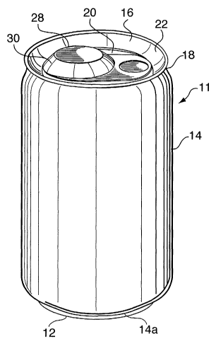
FIG. 1 is a perspective view of a can embodying
the present invention in a particular form;
FTG. 2A is an enlarged and somewhat simplified
fragmentary elevational sectional view of a portion of
the lid member of the can of FIG. 1, including the
CA 02453552 2004-O1-13
WO 03/006329 PCT/CA02/01076
18
aperture-defining flange and closure member;
FIG. 2B is a highly simplified and schematic
representation of the same view as FIG. 2A;
FIG. 3 is a view similar to FIG. 2A of a flexible
closure member bonded to a conventional planar flange
defining an aperture;
FIG. 4 is a fragmentary view similar to FIG. 3 of
a portion of the flange and closure member of the
embodiment of the invention shown in FIGS. 2A and 2B;
FIG. 5 is a simplified and somewhat schematic top
plan view of the can of FIG. 1;
FIG. 6 is an exploded diagrammatic elevational
sectional view of the can lid and closure member of
FIG. 5;
FIG. 7 is a plan view of the closure member of
FIG. 5;
FIG. 8 is a side elevational view, partly broken
away, of two cans having the structure shown in FIG. 1,
illustrating the ability of the cans to be stacked
vertically;
FIG. 9 is a view similar to FIG. 2B illustrating a
condition oflexcessive bulging of the closure member;
FIG. 10 is a graph representing the relationship
between sealing temperature and peel strength in
Example 2 described below;
FIG. 11 is a graph representing the relationship
between heat seal temperature and burst pressure in the
same example;
FIG. 12 is an enlarged fragmentary sectional
elevational view of a portion of a lid member embodying
the present invention;
CA 02453552 2004-O1-13
WO 03/006329 PCT/CA02/01076
19
FIG. 13 is a schematic fragmentary sectional
elevational view of a lid member embodying the
invention;
FIG. 14 is a graph showing bulge height of an
exemplary closure member as a function of pressure
within the can (i.e., differential pressure
FIG. 15 is a schematic plan view of a can lid
embodying the invention and having a "stay-on" closure
member;
FIG. 16 is a graph showing 90E peel force as a
function of displacement of the closure member of FIG.
15;
FIGS. 17A and 17B are highly schematic fragmentary
elevational sectional views in illustration of a
further embodiment of the invention including a
fragrance reservoir;
FIG. 18 is a sectional elevational view of one
form of can lid embodying the invention and including a
fragrance reservoir;
FIGS. 19 and 20 are views similar to FIG. 15 of
two can lids embodying the invention and including both
a stay-on closure member and a fragrance reservoir;
FIG. 21 is a sectional view of another form of can
lid embodying the invention, in which the conventional
countersink is omitted;
FIG. 22 is an elevational view of a further
embodiment of the can of the invention, having a
reduced-diameter body neck and lid;
FIG. 23 is an enlarged fragmentary perspective
view of the upper portion of the can of FIG. 22,
showing the lid with the heat-sealed closure member in
place;
CA 02453552 2004-O1-13
WO 03/006329 PCT/CA02/01076
FIG. 24 is a view similar to FIG. 23 with the
closure member removed;
FIG. 25 is an elevational view of another
embodiment of the can of the invention;
5 FIG. 26 (prior art) is an exploded and highly
schematic sectional view in illustration of a system
for producing a conventional drawn and ironed can body;
FIG. 27 is a fragmentary view, similar to FIG. 26,
of one form of modification of the system of FIG. 26
10 for producing the body of the can of FIG. 25;
FIG. 28 is an elevational view of the can body as
formed by the system of FIG. 27;
FIG. 29 is a view similar to FIG. 27 of an
alternative modification of the system of FIG. 26 for
15 producing the body of the can of FIG. 25;
FIGS. 30A, 30B and 30C are simplified fragmentary
elevational sectional views of can lids in accordance
with the invention respectively~having a conventional
countersink, a countersink of reduced dimensions, and
20 no countersink;
FIGS. 31A, 31B, 31C, 31D and 31E are simplified
and greatly enlarged fragmentary perspective views of
types of stiffening features that may be formed in a
can lid;
FIGS. 32A and 32B are, respectively, a plan view
and an elevational sectional view of a can lid,
embodying the invention and omitting a countersink,
with added stiffening features;
FIGS. 33A and 33B are, respectively, a plan view
and an elevational sectional view of another can lid,
embodying the invention and omitting a countersink,
with added stiffening features; and
CA 02453552 2004-O1-13
WO 03/006329 PCT/CA02/01076
21
FIGS. 34A and 34B are, respectively, a plan view
and an elevational sectional view of yet another can
lid, embodying the invention and omitting a
countersink, with added stiffening features.
Best Modes For Carrying Out The Invention
The container of the invention will be described,
with reference to the drawings, as embodied in a metal
can 10 for holding a carbonated beverage such as soda
or beer. The can 10 includes a~one-piece can body 11
constituting the bottom 12 and continuous, upright,
axially elongated, generally cylindrical side wall 14
of the can, and. a lid 16 which, after the can has been
filled with the beverage, is peripherally secured to
the open top end of the can body to provide a complete,
liquid-tight container.
In this embodiment, the body 11 may be an entirely
conventional drawn-and-ironed aluminum alloy can body,
identical in structure, alloy composition, method of
fabrication, configuration, gauge, dimensions and
surface coatings to can bodies currently commercially
used for carbonated and other beverages (alternatively,
for example, the body may be a steel can body, such as
are in common use in Europe). In particular, and in
common with known can bodies, the bottom 12 of the body
11 is externally concave and the open top end of the
body has a circular edge 18 lying in a plane
perpendicular to the vertical geometric axis of the
side wall 14. The terms "aluminum" and "aluminum
alloy" are used interchangeably herein to designate
aluminum metal and aluminum-based alloys.
CA 02453552 2004-O1-13
WO 03/006329 PCT/CA02/01076
22
Except as hereinafter described, the lid 16 may
also be a generally conventional aluminum alloy lid
member of the type currently commercially used for
beverage cans having drawn and ironed one-piece can
bodies such as the body 11. Thus, the alloy of which
it is constituted, the steps and procedures employed in
its fabrication (with the exceptions noted below), and
its general overall configuration, dimensions, gauge
and surface coatings as well as the manner in which it
is secured to the top edge 18 of the can body 11, may
all be the same as in the case of present day can lids
well-known in the art.
It should be noted, however, that since the can
lid of the present invention is not subjected to the
rivet-forming and scoring operations that must be
performed on currently conventional can lids, since the
strength and rigidity necessary for the conventional
rivet and tab area to withstand the lever action are
not required, and since gauge and strength requirements
related to the presence of a score line do not apply,
the invention permits the use of nonconventional can
lid alloys, materials and/or lid gauges. For example,
coated steel can lids, which are normally too difficult
to open by the conventional scoring mechanisms, could
be used in the practice of the invention. The current
gauge used for AA 5182 alloy lids could be reduced
and/or the alloy composition could be modified by
reducing the proportion of Mg, thereby lowering costs.
Similarly, AA 5182 alloy could be replaced as the alloy
of the lid with a lower cost, lower strength alloy such
as AA 3104 alloy or AA3004 alloy, commonly used for can
bodies (but not, heretofore, for can lids). Used at an
CA 02453552 2004-O1-13
WO 03/006329 PCT/CA02/01076
23
appropriate gauge, AA 3104 alloy or AA 3004 alloy may
have sufficient strength for the lid. structure of the
present invention; it could offer the advantages of
lower cost as compared to the AA 5182 alloy currently
used for can lids and would also afford benefits for
recycling, in that the can lid and body would be made
of the same alloy.
In particular, the lid 16 in this illustrated
embodiment is substantially rigid, and has a
substantially flat upper surface 20 with a circular
periphery, around which is formed a raised annular rim
22 projecting upwardly above the plane of the flat
upper surface 20. When the lid is mounted on the open
upper end of a beverage-filled can body, in known
manner, the rim 22 engages the upper edge 18 of the can
body; the circular flat surface 20 lies substantially
in a horizontal plane, perpendicular to the vertical
geometric axis of the cylindrical side wall 14, and is
centered with respect to the latter axis.
The lower end 14a of the side wall 14 of the can
10 is shaped (tapered) to interfit with the rim 22 of
the lid of another identical can 10a, when the can 10
is stacked vertically on top of the can 10a as shown in
FIG. 8. A multiplicity of the cans may thus be stably
vertically stacked, one on another, as is true of
present-day conventional cans of the same general type.
The elevation of the lid rim 22 above the flat upper
surface 20 of the lid, together with the concavity of
the can bottom 14, cooperatively define a central gap
or space between the lid of one can and the bottom of
the next can above it, in such a stacked arrangement.
CA 02453552 2004-O1-13
WO 03/006329 PCT/CA02/01076
24
Also in common with present-day conventional lid
members used with one-piece drawn-and-ironed aluminum
alloy beverage can bodies, the lid 16, when secured to
the beverage-filled can body, provides therewith a
complete sealed enclosure holding the beverage. The
lid is thus subjected to elevated internal pressure
within the can (i.e., pressure higher than ambient
atmospheric pressure) if the beverage is carbonated.
However, the formed aluminum alloy lid is substantially
rigid, so that it undergoes at most only a small
deflection of its upper surface as a result of this
pressure condition, and the upper surface 20 remains
substantially flat notwithstanding the internal
pressure acting on the lid.
The lid 16 is arranged to provide an aperture
through which the beverage contained in the can may be
poured or removed by drinking directly from the can,
either with a straw inserted through the aperture or by
juxtaposition of the consumer's mouth to the aperture.
Heretofore, in cans for holding carbonated beverages or
other such contents at elevated pressure, the aperture-
providing feature has conventionally included a scored
portion of the metal of the lid member and a riveted
pull tab system for parting the lid metal along the
score line to open the aperture.
The present invention, in contrast, provides a
pre-formed open aperture 24 in the lid, and a peelable,
flexible closure member 2~ covering the aperture. In
order to achieve adequate burst resistance without
requiring excessive force to peel the closure member, a
shallow upwardly projecting annular flange 30 is formed
in the lid within the area of the flat upper surface
CA 02453552 2004-O1-13
WO 03/006329 PCT/CA02/01076
20, to surround and define the aperture 24 and to
provide a seat for the closure member. For purposes of
illustration, the flange 30 and its counterparts in
other embodiments of the invention hereinbelow
5 described are shown as frustoconical (i.e., having
straight-sided upwardly sloping outer surfaces), but it
is to be understood that the upwardly sloping outer
surface of such a flange, in cans and lids of the
present invention, may alternatively be a curved '
10 sloping surface.
More particularly, the flange 30 projects upwardly
from the upper surface 20 of the lid, and has an
upwardly sloping outer flange surface 32 and an annular
inner edge 34 defining the aperture 24, which is
15 illustrated as being of circular configuration but is
not limited to a circular shape. The inner edge 34, as
shown in FIGS. 2A and 2B, is preferably formed as a
bead 36 with a reverse curl, which is tangent to a
horizontal plane represented by line P (FIGS. 2A and
20 2B) and to the line of slope of the outer flange
surface 32 so that, once the closure member 23 is heat-
sealed to the flange surface, the cut metal (typically
an aluminum alloy) at edge 34 cannot come into contact
with the contained beverage. This is advantageous
25 because the cut metal at the edge (unlike the major
surfaces of the lid) has no protective coating, and
would be attacked by acidic or salt-containing
beverages if it were exposed thereto. The reverse curl
of bead 36 also prevents a drinker's lips from touching
and being injured by the cut metal at edge 34, and
avoids any possibility of damage to the closure member
by contact with the cut metal. However, the invention
CA 02453552 2004-O1-13
WO 03/006329 PCT/CA02/01076
26
may also be embodied in a can wherein the aperture has
a standard (not reverse) bead curl, which also affords
such benefits as safety for the consumer, it being
noted that where the cut edge of the metal is not kept
from contact with the contained liquid by a reverse
curl, it may be protected by application to the cut
edge of a lacquer.
The flexible closure member 28 is constituted of a
sheet material comprising metal foil, e.g. aluminum
foil; in the described embodiment of the invention, the
closure member is fabricated of a suitably lacquered
aluminum foil sheet or an aluminum foil-polymer
laminate sheet. Stated more broadly, materials that
may be used for the closure member include, without
limitation, lacquer coated foil (where the lacquer is a
suitable heat seal formulation); extrusion coated foil
(where the polymer is applied by a standard or other
extrusion coating process); the aforementioned foil-
polymer laminate, wherein the foil is laminated to a
polymer film using an adhesive tie layer; and foil-
paper-lacquer combinations such as have heretofore been
used for some low-cost packaging applications.
The closure member extends entirely over the
aperture 24 and is secured to the flange outer surface
32 by a heat seal extending at least throughout the
area of an annulus entirely surrounding the aperture.
Since the reverse curl bead 36 does not project beyond
the slope of the flange outer surface, the closure
member smoothly overlies this bead as well as the
flange outer surface, affording good sealing contact
between the closure member and the flange.
CA 02453552 2004-O1-13
WO 03/006329 PCT/CA02/01076
27
The closure member, in the described embodiment of
the invention, is bonded by heat sealing to the flange
30, covering and closing the aperture 24, before the
lid member 16 is secured to a can body 11 filled with a
carbonated beverage. Once the lid has been mounted on
the body to complete the enclosure of the beverage,
elevated pressure generated by the beverage acts on the
inner surface portion of closure member 20 which is
exposed through the aperture to the interior of the
can, causing the flexible closure member to bulge
outwardly. Further in accordance with the invention,
however, the angle 8 (FIG. 2A) of slope of the flange
outer surface relative to the plane of the annular edge
34 (i.e., plane P) is selected to be such that a line
r
tangent to the arc of curvature of the bulged closure
member at the inner edge of the flange lies at an angle
to plane P not substantially greater than the angle 8
of slope of the flange outer surface. As indicated in
FIG. 2B, since the upper surface 20 of the lid member
16 is flat and horizontal (and thus parallel to plane
P), 8 may alternatively be defined as the angle of
slope of the flange outer surface to the flat lid
surface 20.
Preferably the angle 8 is between about 12.5° and
about 40° to the plane P; a more preferred lower limit r
or 0 is about 15°, and a more preferred upper limit is
about 35°, or even in some instances about 30°. In
currently particularly preferred embodiments, the angle
B of slope is between about 20° and about 35° to the
plane P.
After initial forming of the flange there is some
spring-back of the metal so that tooling with a 35°
CA 02453552 2004-O1-13
WO 03/006329 PCT/CA02/01076
28
forming angle will result (after spring-back) in a
flange angle of about 30°. Furthermore, when the can
is pressurized, the can end bows and the effective
flange angle is further reduced, by an amount which
depends on the internal pressure but is typically a few
degrees. For the burst resistance calculations
discussed below, it is the actual angle of the flange
when the can is pressurized that is relevant (i.e.,
after spring-back and the bowing of the can end are
taken into account) and not the angle of the forming
tool.
In FIGS. 2A and 2B, A is the diameter of the
aperture 24 in plane P, R is the radius of curvature of
the bulged or domed closure member 28, and h is the
'maximum vertical height of the domed closure member
above the aperture plane P. In these figures, the foil
closure is shown domed to the point at which the flange
is tangential to the arc of the domed foil closure
member 28, i.e., at which the line of slope of the
flange surface 32 as seen in a vertical plane is
tangent to the arc of curvature of the closure 28 (as
seen in the same vertical plane) at the edge of
aperture 24.
For the closure configuration illustrated in FIGS.
2A and 2B, the forces acting on the heat sealed flange
area due to the tension in the foil, are predominantly
shear in character, with no significant peel force
component. In this case, the burst resistance will
depend on the shear strength of the heat seal joint or
the bulge strength of the foil or foil laminate itself.
This ensures that the burst resistance of the lid is
CA 02453552 2004-O1-13
WO 03/006329 PCT/CA02/01076
29
enhanced significantly compared to that of a standard
heat sealed container.
Heat seal bonds are strong under shear loading,
especially at ambient temperature, and an annular heat
seal about 2 mm - 3 mm wide is sufficient to resist the
anticipated shear forces which result from the internal
pressure. If the foil is domed to a lesser extent than
shown in FIGS. 2A and 2B, relative to the flange slope
angle 8, the foil laminate will tend to hold down the
heat seal bond with a corresponding additional
enhancement of the burst resistance. If, however, the
foil were domed to a greater extent than is shown in
FIGS. 2A and 2B, relative to the flange slope angle, a
peel force component would arise at the inner edge of
the aperture, with an increased likelihood of burst
failure.
The frustoconical aperture-defining flange enables
provision of a flange slope angle A sufficient to
accommodate the extent of doming or bulging of the
closure member to be used therewith, under the elevated
internal pressures for which the can is designed, and
thereby enables the burst resistance to be enhanced
significantly, for a closure with a peel force which is
acceptable to the consumer. The peel force is
dependent both on the inherent peel properties of the
selected heat seal lacquer system, and on geometric
effects associated with the complex bending and
distortion which the closure foil undergoes during
peeling.
As will therefore be clear, the flange slope angle
and the form of the foil closure strongly influence the
burst resistance. In addition to the flange slope
CA 02453552 2004-O1-13
WO 03/006329 PCT/CA02/01076
angle and extent of doming of the closure, not only the
resistance of the heat seal bond to shear forces but
also the strength of the foil of the closure member are
selected to withstand the forces acting thereon. If
5 the flange slope angle, in accordance with the
invention, is such as to substantially avoid any
substantial peel force component of forces acting on
the heat sealed area owing to tension in the foil from
the internal pressure acting on the closure member, and
10 if the heat seal bond and the shear resistance of the
bond are adequate, burst failure could occur by failure
of the foil itself. The shear force required to break
the heat seal bond can be adjusted either by increasing
the width. of the heat sealed region, or by selecting
15 laminates or coating formulations which achieve a
higher shear strength. Both of these expedients,
however, would increase the peel force required to open
the container.
The effect of heat sealing the closure member 28
20 to a sloping flange surface rather than a horizontal
flange surface, will be apparent from a comparison of
FIGS. 3 and 4. FIG. 3 represents an aperture 40 in a
conventional lid member 41 wherein the flange 42 around
the aperture is simply a flat horizontal portion of the
25 lid upper surface, coplanar with the aperture edge 43.
A flexible closure member 44 covering the aperture 40
and bonded by heat sealing to the coplanar flange 42
will bulge, in the same manner as the closure member 28
in FIG. 2A, if the lid member 41 is mounted on a can
30 body filled with a carbonated beverage or other
pressure-generating contents. Assuming that equal
elevated pressures exist within the cans of FIGS. 2A
CA 02453552 2004-O1-13
WO 03/006329 PCT/CA02/01076
31
and 3, that the diameters of apertures 24 and 40 are
equal, and that the same flexible sheet material is
used for the closure members 28 and 44, the extent of
bulging of the closure members (defined by h and R)
should be essentially identical in both cans. In the
case of the planar flange of FIG. 3, the consequent
tension force FT acting on the heat-seal-bonded portion
of the closure member 44 at the edge of the aperture 40
will have a substantial peeling force component FP
acting at 90° to the plane of the flange surface. In
the case of the sloping flange of the invention,
however, as shown in FIG. 4, owing to the above-
described relation of angle ~ to the angle of the
tangent to the arc of curvature of the domed closure
member 28 at the aperture edge 34 (in which, in FIG. 4,
the reverse curl is omitted for simplicity of
illustration), the same tension force FT (which acts in
the direction of the aforementioned tangent at the edge
of the aperture) has no significant peeling force
component FP acting in direction D at 90E to the plane
of the (sloping) flange surface 32.
Under the pressures that may obtain within a can
of carbonated beverage, the peeling force component FP
acting on a flange that is coplanar with the aperture
edge can be sufficient to cause the closure member to
progressively separate from the flange by peeling until
it bursts open, at least if the strength of the heat
seal bond is within conventional limits as desired for
ease of peeling by a user. The sloping of the flange
prevents this from happening, and thereby increases the
burst resistance of the heat-sealed closure member
sufficiently to enable its safe use on a carbonated
CA 02453552 2004-O1-13
WO 03/006329 PCT/CA02/01076
32
beverage can without having to increase the heat seal
bond strength to a point which would make the closure
member difficult to remove by a user.
It will be understood that the extent of bulging
of the closure member under the influence of pressure
within the can, and thus the angle of the tangent
(relative to plane P) to the bulged or domed closure
member at the aperture edge, is dependent on the
pressure within the can and the elastic deformability
of the closure member. Desirably, the slope angle A of
the flange surface 32 should be chosen to be
sufficiently large so as to be compatible with the
bulging characteristic of the chosen closure member
material. The provision of the flange, which serves as
a seat for the heat sealing of the closure member, as a
frustoconical projection from a (preferably
substantially flat) upper surface of a substantially
rigid lid, facilitates this provision of a relatively
large slope angle. At the same time, by making the
aperture area a minor fraction of the total area of the
can open end, the height h of the domed closure may
readily be kept sufficiently small to be accommodated
between the lid of one can and the concave bottom of
another when the cans are stacked vertically as shown
in FIG.
Further, it will be understood that the benefits
of the invention may be realized even if the flexible
closure member bulges slightly beyond the ideal limit
of tangency to the slope of the flange. In such a
case, the peel component of force will start to grow,
but may still be insufficient to cause failure of the
bond.
CA 02453552 2004-O1-13
WO 03/006329 PCT/CA02/01076
33
FIGS. 5 - 7 illustrate further the configuration
and arrangement of the flange, aperture and closure
member at the top of the can in the embodiment of FIG.
1. With a circular can lid member 16 having a diameter
of 48 mm, mountable on a can body having a
correspondingly dimensioned circular open upper end, a
circular aperture 24 having a diameter of 20 mm is
defined by a frustoconical annular flange 30 having a
maximum diameter (in the plane of lid surface 20) of 30
mm. As best seen in FIG. 7, the foil-polymer laminate
closure member 28 has a circular central portion 32 mm
in diameter (large enough to completely overlie the
sloping outer surface of the flange), with a short
projection 28a on one side for overlying part of the
flat upper surface of the lid and an integral tab
portion 28b on the opposite side which, outwardly of
the flange 30, is not heat sealed but is free to be
bent and pulled. The exploded diagrammatic elevational
view of FIG. 6 indicates the relative positions of the
can lid 16 and the closure member 28, as well as the
folding of the tab. The closure member is subjected to
a preliminary forming step to impart a frustoconical
shape (also indicated in FIG. 6) to its circular
central portion for proper seating on and sealing to
the flange 30.
The aperture 24 is shown in FIG. 5 as being
disposed eccentrically of the geometric center (center
of symmetry) of the can lid 16, i.e., relatively close
to the edge of the lid, so that a user can easily bring
the aperture to his or her mouth for drinking the
contained beverage directly from the can. However,
depending on use and contents, different positions for
CA 02453552 2004-O1-13
WO 03/006329 PCT/CA02/01076
34
the aperture may be employed. Also, if desired,
aperture configurations other than the circular shape
shown may be provided.
The manufacture of the can of the invention,,
including particularly the lid and closure, may (as
stated) be in many respects generally conventional.
However, certain modifications of conventional practice
and equipment, now to be described, are employed to
achieve the novel flange shape and the heat sealing of
the closure member thereto.
Illustratively, but without in any way limiting
the invention thereto, the foil closure stock may be a
suitable aluminum foil (e.g. made of alloy AA3104 or of
a conventional foil alloy such as AA3003, 8011, 8111,
1100, 1200) with a foil gauge of 50 to 100
(0.002" - 0.004") which is either lacquered on one side
with a suitable heat sealable lacquer, or laminated on
one side with a suitable heat sealable polymer film
(e.g., polyethylene, polypropylene, etc.), 25 to 50
(0.002" - 0.002") thick. The other (outwardly exposed)
side should have a suitable protective lacquer coating.
It may be desirable to print onto the foil using
rotogravure, flexographic or another known printing
method. It may also be desirable to emboss the
laminate, or just the pull tab portion thereof, to
provide an attractive surface texture which enhances
the appearance of the closure and assists in opening by
making the closure easier to grip.
In order to seal to the aperture, the closure
members 28 with their described integral pull tabs are
formed and stamped out from the foil laminate stock
using a suitable press (standard presses can be used
CA 02453552 2004-O1-13
WO 03/006329 PCT/CA02/01076
with tooling specifically designed for these closure
members). In the embodiment where the frustoconical
flange is preformed, the foil closure members are
preshaped (by a drawing process) so that they will fit
5 over the raised aperture of the lid.
A heat sealing machine with suitable tooling is
used to heat seal the closures to the can lid. In the
case where the frustoconical flange is preformed, the
heat seal tooling is designed to conform to the flange
10 shape. That is to say, the tooling is angled to match
the flange (and the formed closure member). The exact
heat sealing conditions are dependent on the polymer
and heat seal coating formulation used. The
temperature of the bottom heat sealing tool should be
15 selected so that the coating on the inside of the lid
member should not be significantly softened or melted
during the heat sealing operation. For the commonly
used can end coatings and for heat seal dwell times of
about 0.3 sec. or less, the temperature should be less
20 than about 220°C and preferably about 200°C or below.
The upper tool temperature is set to ensure that the
heat seal bond is achieved in an acceptably short time.
Typical commercial heat sealing machines have dwell
times of 0.3 sec. The dwell time, pressure and
25 temperatures may be optimized for the particular heat
seal application. Heat sealing the closure to the lid
involves use of a customized heat sealing line (such as
those built by Hans Rychiger AG, Steffisburg,
Switzerland), with appropriately constructed heat seal
30 tooling provided to bond the closure to the angled
aperture.
CA 02453552 2004-O1-13
WO 03/006329 PCT/CA02/01076
36
The forming of the can lid member 16 itself with
the frustoconical flange 30 and aperture 24 as
described is relatively straightforward, using modified
can end forming tooling, with provision for forming the
reverse curl bead 36. The can lids of the invention do
not require the formation of a rivet or tab.
The lids, complete with heat sealed closures, are
substantially compatible with existing can filling
lines and will be a direct replacement for the
currently commercially used lids for cans for
carbonated beverages and the like. Modifications may
be made in the lid handling equipment to minimize or
eliminate the possibility of damaging the raised
aperture and closure.
Alternatively, in the currently preferred method
of fabrication, the can lid may initially be provided
with the aperture 28 and reverse curl bead 36 around
the edge thereof, and the closure member 28 may be heat
sealed to the upper surface of the lid in covering
relation to the aperture, before the upwardly sloping
frustoconical configuration is imparted to the flange
portion of the lid immediately surrounding the
aperture. Forming of the frustoconical flange 30 then
proceeds, with concomitant deformation of the already
heat sealed foil closure member, followed by mounting
of the lid on a can body already filled with carbonated
beverage.
As initially applied to the can lid, the portion
of the closure member 28 extending across the aperture
may be substantially planar as indicated at 28c in FIG.
12, which shows a frustoconical flange 30 having an
angle.of slope A of 23°. When the lid is mounted on a
CA 02453552 2004-O1-13
WO 03/006329 PCT/CA02/01076
37
can body filled with a carbonated beverage, so as to
completely enclose the beverage, the resultant pressure
within the can creates a positive differential pressure
~p causing the deformable closure member to bulge
upwardly. FIG. 13 illustrates the location of the heat
seal annulus 46 on the sloping outer surface of the
frustoconical flange 30.
A particular feature of the present invention is
the dimension of the aperture 24. There is a consumer
preference for cans with good pouring characteristics
(good~pour rate with a smooth, streamlined flow). Cans
with large opening ends (LOEs) have been introduced in
recent years and have been successful, especially for
beverages with lower carbonation levels (e. g. lemonade
and iced tea), although in the case of highly
carbonated beverages, problems with score line failure
and burst resistance have been encountered. A
conventional shape of apertures for beverage cans is
approximately oval with an aspect ratio between about
1.1 and about 1.5. A standard aperture is 17.8 mm in
diameter and an L0E is 25.4 mm x 17.8 mm; thus, the
current aperture size for a carbonated beverage
container, expressed as average diameter, is from about
17.8 mm to about 22.2 mm.
Some can designs have also provided a separate
vent hole in the lid to improve pouring and drinking
characteristics, but the inclusion of the vent hole
adds to manufacturing cost and may complicate the
opening process for the consumer.
The aperture size and shape are important in
determining pouring and drinking characteristics. In
general, larger aperture sizes give better flow rates
CA 02453552 2004-O1-13
WO 03/006329 PCT/CA02/01076
38
with a more even flow. The relation between aperture
and flow rates is illustrated by the following test
data obtained in experimental pouring tests with the
can tilted from the upright position through an angle
of 120°, so that the can walls make an angle of 30° to
the horizontal, and oriented so that the aperture is at
its lowest point on the can end:
TABZE 1
Aperture Pour Rate (g./sec.)
Standar d can aperture 56
Z0E 70
0.5625" (14.3 mm), flat flange 18
0.625" (15.9 mm), flat flange 31
0.750" (19.0 mm), flat flange 50
0.875" (22.2 mm), flat flange 75
0.5625" (14.3 mm), angled flange 24
0.625" (15.9 mm), angled flange 35
0.750" (19.0 mm), angled flange 56
0.875" (22.2 mm), angled flange 93
In the above table, "angled flange" means an
upwardly sloping frustoconical flange as provided in
the present invention; "flat flange" means that the
portion of the lid surrounding the aperture is
substantially coplanar with the aperture edge, as in
conventional can lids.
As will be apparent from Table 1, for equivalent
hole sizes, the pour rate for "angled flange" apertures
is higher by about 10 to 15o at a 30° tilt than that
for "flat flange" apertures. The 19 mm angled flange
aperture has a pouring rate at 30° tilt approximately
the same as that of the current standard can aperture.
CA 02453552 2004-O1-13
WO 03/006329 PCT/CA02/01076
39
The 14.3 mm aperture (with both flat and angled
flanges) has a significantly lower pour rate than that
of the current standard can aperture. The 22.2 mm
angled flange aperture provides a higher pour rate than
the LOE design (which, like the standard can, has a
flat flange). For the aperture range of interest, the
pour rate is approximately proportional to aperture
area.
As hereinafter further explained, the tear/shear
forces acting on the closure member and seal tend to
increase with aperture size, so that the maximum
aperture diameter is limited by the need to provide a
can with adequately high burst pressure or burst
resistance (i.e., the pressure at which the closure
member and seal rupture or fail). Therefore, the range
of average aperture diameter in accordance with the
present invention is between about 15.9 mm and about
25.4 mm, to afford satisfactory pour rates (without any
separate vent hole) and at the same time to achieve
high burst resistance without sacrifice of other
characteristics such as peelability.
Another important characteristic, for attainment
of adequately high burst resistance, is the tear/shear
force.imposed on the heat seal and closure member by a
given differential pressure. The tear/shear force y
(lb./in.) is determined by the differential pressure ~p
(psi), aperture diameter A (cm) and angle of slope ~ of
the frustoconical flange 30, in accordance with the
relation
A~~p
Y - _______ (1)
4 sin A
CA 02453552 2004-O1-13
WO 03/006329 PCT/CA02/01076
In particular instances, depending (for example)
on the degree of carbonation of the contained beverage
and the consequent magnitude of differential pressure
that the can, closure and seal must be designed to
5 withstand, the design value of tear/shear force
resistance for a can in accordance with the invention
(i.e., the value that the closure member and heat seal
must be able to withstand) may range from less than (or
about) 4.5 kg/cm (25 lb/in.) to about (or even somewhat
10 more than) 13.4 kg/cm (75 lb./in.), a tear/shear
resistance of about 13.4 kg/cm (75 lb./in.) being
currently preferred in many cases. Typical filling
line pressures for carbonated beverages are between
about 345 and about 414 kPa (50 - 60 psi), though for
15 some beverages (sports drinks, lemonade, etc.), lower
carbonation levels are used. However, in order to take
account of extreme conditions (temperature, agitation,
etc.) a minimum test burst pressure requirement of 620
kPa (90 psi) is currently specified for many
20 applications, and a burst resistance of 689 kPa would
be even more desirable.
Table 2 sets forth values calculated using
relation (1) above for tear/shear force y (kg/cm) for
various aperture diameters A and flange slope angles
25 at a differential pressure ~p of 7.03 kg/cm2 (100 psi).
CA 02453552 2004-O1-13
WO 03/006329 PCT/CA02/01076
41
TABLE 2
y(kg/cm)
e A(cm)= 1.27 1.59 1.90 2.22 2.54 2.86 3.17
2.5 51.2 64.0 76.8 89.6 102.4 115.2 127.9
25.6 32.0 38.4 44.8 51.2 57.6 64.0
7.5 17.1 21.4 25.6 29.9 34.2 38.5 42.8
12.9 16.1 19.3 22.5 25.7 28.9 32.1
12.510.3 12.9 15.5 18.1 20.6 23.2 25.8
8.6 10.8 12.9 15.1 17.3 19.4 21.6
17.57.4 9.3 11.1 13.0 14.8 16.7 18.6
6.5 8.2 9.8 11.4 13.1 14.7 16.3
22.55.8 7.3 8.7 10.2 11.7 13.1 14.6
5.3 6.6 7.9 9.3 10.6 11.9 13.2
These are the minimum strength requirements
(kg/cm) for the closure member and heat seal to
5 withstand a pressure differential ~p of 7.03 kg/cm~
(100 psi) without rupture or failure (bursting), for
each specified combination of aperture diameter A and
slope angle 8. As is apparent, for a given
differential pressure, the tear/shear force strength
10 requirement decreases with increasing flange angle and
increases with increasing aperture diameter.
By way of illustration, an aperture diameter of
22.2 mm and a flange angle of about 22.5° would require
a closure foil with a breaking strength in excess of
15 10.2 kg/cm and an equivalent minimum heat seal shear
strength, for burst resistance of 689 kPa (100 psi).
Typical aluminum lidding foils of 0.076 mm
(0.003 inch) thickness can withstand a tear force in
excess of 13.4 kg/cm (75 lb./in.). Practicable heat
20 seals capable of withstanding a shear force of
CA 02453552 2004-O1-13
WO 03/006329 PCT/CA02/01076
42
13.4 kg/cm (75 lb./in.) can also readily be provided,
in configurations suitable for the heat seal 46.
Therefore, combinations of A and ~ in Table 2 for which
the calculated value of y is 13.4 kg/cm (75 lb./in.) or
less enable satisfactory and practicable attainment of
a burst resistance of 7.03 kg/cm2 (100 psi) in the can
of the present invention.
As already stated, to avoid a peel component in
the force exerted on the closure member and heat seal
by the differential pressure gyp, the bulge height h of
the closure member above the plane P of the aperture 24
should not exceed a value hmax at which the slope of the
flange 30 is tangent to the arc of the bulging closure
at the edge of the aperture. This upper limiting value
hmax (in mm) is, again, determined by the angle of slope
8 of the flange and the aperture diameter A (in mm) of
the aperture 24; in the case of a circular aperture,
such limiting value can be calculated using the
relation
A 1 1
hmax = - (_____ _ _____) (2)
2 sin 8 tan B
It will be seen that the maximum permitted bulge
height, to achieve the described freedom from any peel
component, increases with aperture diameter and also
increases with flange angle.
The actual bulge height in a closure mdmber 28
produced by a given differential pressure ~p is
dependent on the properties of the closure foil related
to deformation, i.e., the deformability of the foil, as
well as on the aperture diameter. FIG. 14 illustrates
CA 02453552 2004-O1-13
WO 03/006329 PCT/CA02/01076
43
the relationship of bulge height h (here given in mm)
to pressure Op for a 22.2 mm (7/8 inch) aperture
diameter and an exemplary aluminum foil 100 ~ (0.004
inch) thick. The Figure has been corrected for the
small initial displacement of the foil relative to the
flange (i.e., the foil was not perfectly flat after the
forming and springback). The measurements were made
with a lid clamped into place in the "buckle-tester."
The position of the center of the foil covered aperture
was measured carefully (using a precision laser
measurement device) and the pressure was gradually
increased. Measurements were taken at intervals of 10
psi up to 80 psi and the displacement at each pressure
was computed and plotted in FIG. 14.
Examples of the maximum permitted bulge height
(inches) as defined above, calculated for a circular
aperture using relation (2), for various combinations
of A (in mm) and ~, are set forth in Table 3:
TABZE 3
hmax (~)
A(mm) 8 - 17.5 20 22.5 25 27.5 30
15.9 1.2 1.4 1.6 1.7 1.9 2.1
19 1.5 1.7 1.9 2.1 2.3 2.5
22.2 1.7 1.9 2.2 2.5 2.7 3.0
25.4 1.9 2.2 2.5 2.8 3.1 3.4
For an aperture diameter of 22.2 mm with a flange
slope angle of 22.5°, the maximum bulge height should
be 2.2 mm to avoid peel force components.
If the bulge height exceeds the critical value,
FIG. 14 can be used to determine the angle of the
tangent to the arc of the bulging closure foil at the
CA 02453552 2004-O1-13
WO 03/006329 PCT/CA02/01076
44
edge of the aperture. If the stress within the foil
can be determined, the peel component of the stress can
be estimated. Provided that this component is less
than the measured peel stress for the closure material,
failure by peeling will not occur. However, it is
preferred that the lid parameters be chosen to ensure
that the bulge height does not exceed the above-defined
limiting value at least for differential pressures up
to 620 kPa (90 psi), more preferably for differential
pressures up to 689 kPa (100 psi).
Metal foils have comparatively good creep
resistance over the range of temperatures that may be
experienced in service, and therefore afford an
important advantage over polymeric closure member
materials with respect to creep susceptibility and
consequent short shelf life. Since creep is dependent
on applied stress, increasing the thickness of the
closure material can reduce or eliminate creep. For
aluminum foil closure members, a thickness of about
75 - 100 ~ (0.003 - 0.004 inch) is sufficient to
virtually eliminate creep.
The performance of the bond between the closure
membrane and the lid flange is dependent on the
properties of the adhesive layer and on the design of
the joint. The flange angle is designed to ensure that
the forces between the closure membrane and the flange
are predominantly shear in character under the fully
pressurized conditions of use. However, the shear
stress in the joint can be affected by the width of the
heat seal; i.e., increasing the width of the bond
spreads the load and thereby reduces the stress
intensity.
CA 02453552 2004-O1-13
WO 03/006329 PCT/CA02/01076
It is desirable for the width of the heat seal to
be less than about 3 mm (0.118 inch) and preferably
about 2 mm (0.079 inch). If the width is increased
above about 3 mm (0.118 inch), the peel force required
5 to open the container will be increased. Furthermore,
an increased heat seal (and flange) width would mean
that the drinking aperture has to be located further
from the container edge, detracting from the
convenience of the consumer by making the container
10 less comfortable and more inconvenient to drink from.
Experimentally, it is found that a 2 mm
(0.079 inch) wide heat seal annulus for the foil
closure performs well in the can of the invention (see
Example 4 below). Fully pressurized cans (60 - 70 psi)
15 have been stored at ambient temperature (~20°C) for
several months, with no detectable sign of creep in
either the foil or in the adhesive bond joint.
In containers for beverages and the like with
manually peelable closures, the peel force required to
30 open the container should preferably fall within the
range between about 8N and 20N (1.8 1b. to 4.5 1b.),
and still more preferably within the range between
about 10N and 16N (2.25 lb.to 3.6 1b.) as measured by a
90E peel test. The peel force required is dependent on
25 the peel strength of the bond and on the effective
width of the seal during the peeling procedure. In the
case of an angled flange, there will also be a
geometrical factor, which will affect the final peel
force required. The strength and gauge of the foil
30 will also contribute to peel strength since the peel
action requires the foil to be bent and deformed.
CA 02453552 2004-O1-13
WO 03/006329 PCT/CA02/01076
46
In the case of heat seal bonding, the peel
strength is influenced by the particular lacquer
formulations on the two mating surfaces, and on the
heat sealing conditions which are used. For example,
in one preferred embodiment, the outer can end panel
surface has a thin vinyl lacquer coating (Valspar
Llnicoat, up to about 2 p thick) and the aluminum foil
closure material has a vinyl based heat seal lacquer
(Alcan Rorschach TH388, between about 5 and 8 ~ thick).
For this combination of coatings, the peel
strength falls within an acceptable range for
peelability. At the same time, provided the closure
foil has sufficient strength, the heat seal bond can
meet the requirements for shear strength.
Variations in peel strength can be obtained by
changes to the heat sealing temperature, the heat
sealing pressure andlor the dwell time for sealing.
In addition to the aforementioned vinyl based
lacquer systems, various other combinations of can end
lacquer and heat seal coatings have been found to be
suitable for the present invention. These are
exemplified, without limitation, as follows:
Can lid coating (exposed side) Foil Closure coating
Epoxy coating (solvent based
lacquer )
Polypropylene (extrusion coated) Polypropylene based
heat
sealed lacquer
Laminated polypropylene Polypropylene
formulation: extrusion
coated
Polyester coated (e. g. extrusion Polyester compatible
coated) heat seal coating
Polystyrene/polyester
blend
CA 02453552 2004-O1-13
WO 03/006329 PCT/CA02/01076
47
It should be recognized that the combination of
specific coating formulations on the can lid (exposed
side) and on the foil closure material (product side)
needs to be carefully selected to provide the desired
combinations of peel strength and shear strength.
Furthermore, the coatings must also provide adequate
protection from any corrosive attack of the metal by
the product. The coatings must also comply with
applicable food/beverage contact regulations.
The coatings, at the thicknesses applied, must
also be capable of maintaining integrity during the
forming operations to which the components of the lid
are subjected. In particular, the coating on the lid
must survive the bead curl forming operation.
It is found that coating formulations based on the
classes of coatings listed above are able to meet all
of these requirements. As will be seen from the above
list, at least one of the two coating formulations (and
preferably both) have a thermoplastic polymer as a
major component (e. g. vinyl, polypropylene,
polystyrene, polyester) and heat sealing is the
preferred method of attaching the closure.
It will also be noted that the adhesion between
the lacquers/coatings and the metal surfaces is
important and suitable cleaning and, optionally,
pretreatment of the foil surface prior to coating is
recommended.
As already stated, for the peelable closures of
the present invention, it is desirable that the foil
closure be relatively easy for the consumer to peel
back from the pouring/drinking aperture. However, it
is also desirable to design the closure in such a way
CA 02453552 2004-O1-13
WO 03/006329 PCT/CA02/01076
48
that the consumer is discouraged from removing the
closure foil completely, since it may then be discarded
as litter. A preferred design of closure for this
purpose is illustrated in FIG. 15, which shows a can
lid 116 having a flat upper surface and an
eccentrically disposed aperture 124 surrounded by an
angled flange to which a foil closure member 128 is
bonded by an annular portion 146a of a heat seal. On
the side of the aperture adjacent the lid edge, the
closure member has an integrally formed pull tab 128b
(folded back over the aperture, with its unfolded
position indicated at 128b'). The closure member also
has an integral "stay-on" extension 128a positioned in
opposed relation to tab 128b (with respect to the
aperture) and overlying the flat upper surface of the
lid. Extension 128a is bonded to the lid by a further
heat seal portion 146c, which is so dimensioned as to
require a substantially greater peeling force (for
separating extension 128a from the lid) than that
required by annular heat seal portion 146a (for
separating the closure member from the angled flange
around the aperture).
In other words, the closure member 128 of FIG. 15
includes a "stay-on" tab area or extension 128a which
is sealed to the lid panel 116 by portion 146c of the
heat seal that has a size and shape which requires a
substantially higher peel force (greater resistance to
peeling) than the annular seal portion 146a surrounding
the aperture 124, thereby discouraging the consumer
from completely removing the closure foil. As a result
of this design, when the consumer peels open the
closure, the peel will initially be within the targeted
CA 02453552 2004-O1-13
WO 03/006329 PCT/CA02/01076
49
range for each opening, e.g. from about 10 to 20N
(2.25 1b. to 4.5 1b.). Then as the aperture is
completely opened, the peel force will fall to a very
low value so that the consumer will sense that the
opening is completed. If the consumer continues to
pull the closure, the required peel force will rise
rapidly to a value which exceeds the normally accepted
easy peel range, i.e. to about 25N (5.5 1b.). An
example of the peel characteristics of a closure of
this invention is given in FIG. 16.
This variation in peel force requirement can be
achieved most readily by careful design of the seal
region, in particular by appropriately selecting the
dimensions of the heat seal portions 146a and 146c. In
the case of a heat sealed closure, this is easily
achieved by the design of the heat seal tooling. With
a pressure sensitive adhesive, it would be more
difficult and would require the adhesive to be printed
onto the closure film in the desired pattern.
FIG. 16 is a graph showing a typical variation of
peel force (90E peel test) as the closure is peeled
open. As the peel is initiated, the force rapidly
increases as the foil peels away from the region of the
flange on the pull tab side 128b. As the foil is
peeled from the remainder of the flange and opens the
aperture, the peel force remains fairly constant,
rising to a second maximum at the end of the aperture.
At this point, the foil is not sealed to the lid, and
0
the peel force falls quickly to a low value. At the
start of the "stay-on" extension region, the peel force
rises to a high value to discourage the consumer from
completely removing the closure foil.
CA 02453552 2004-O1-13
WO 03/006329 PCT/CA02/01076
Further control of the peel force can be obtained
by varying the heat sealing conditions in the different
regions of the closure. For example, if the
temperature of the heat seal in the stay-on extension
5 region were increased, a high peel strength would
result. It ~is also possible to use a different heat
seal lacquer, with a higher inherent peel strength, in
the "stay-on" extension region. Yet another method of
increasing the peel force requirement in the "stay-on"
10 tab region is by the use of one or more ridges or other
profiled features (not shown). Such features would
serve to increase the effective area of the seal and to
provide a degree of mechanical keying for the closure.
As discussed above with reference to FIG. 15, the
15 peel force varies as the closure is peeled baok. The
detailed variation of the peel force required can be
adjusted and controlled by the various methods
described. The variation shown in FIG. 16 corresponds
to a desirable behavior for the consumer, in that the
20 uniform peel force after an initial higher start force
provides ease of opening for the container; the
subsequent drop in peel force gives the consumer an
indication (by feel) that the aperture is completely
opened; and, finally, the rapid rise of the force due
25 to the "stay-on" extension signals the consumer that
the closure is intended to stay on and be folded back
for drinking.
With an aluminum foil closure material, employing
a "stay-on" arrangement as described, the closure can
30 be easily folded down so that it does not significantly
interfere with the drinking experience of the consumer.
Furthermore, since the foil has good dead-fold
CA 02453552 2004-O1-13
WO 03/006329 PCT/CA02/01076
51
characteristics (i.e. it does not exhibit any
noticeable spring back), the closure can be folded back
over the aperture if desired. Although this does not
reseal the can, it would prevent the undesired ingress
of dirt or insects into the beverage between drinks,
and may also reduce the spillage if a can is
accidentally tipped.
Yet another advantageous feature of the invention,
in particular~embodiments as illustrated in FIGS.
17 -~0, is the incorporation of a source of a fragrance
or aroma in the can lid, so that peeling of the closure
member to open the can also acts to expose a small
quantity of an oil or wax based aroma concentrate,
located on the lid in a position which is in close
proximity to the nostrils of a person drinking from the
can aperture. The aroma is selected to enhance or
complement the taste of the beverage.
It is well known that the senses of smell and
taste are closely related, and in particular that the
sense of smell can significantly enhance the taste
experience. Preservation or enhancement of a smell
associated with a particular beverage, thereby
improving the aroma of the product, may serve to
increase the overall enjoyment of the product.
Fragrances which may be thus provided may include (by
way of nonlimiting illustration) lemon, orange, lime,
mint, etc.
The aroma-enhancing feature may, for example,
advantageously be incorporated in.a can lid 116 having
a "stay-on" foil closure member 123 as described above
with reference to FIGS. 15 - 16. A small part of the
lid area, initially covered by the foil closure member
CA 02453552 2004-O1-13
WO 03/006329 PCT/CA02/01076
52
(FIG. 17A) but exposed upon peeling of the closure
member (FIG. 17B), is modified so as to receive a small
quantity 156 of an oil- or wax-based fragrance. This
can be achieved by forming a small upwardly opening
depression or reservoir 158 in the lid 116 (FIG. 18)
and/or by forming a similar receptacle indentation
(facing the lid; not shown) in the foil closure member
itself.
The reservoir, and hence the supply of fragrance,
are disposed on the side of the aperture 124 away from
the edge of the lid so as to be close to the nostrils
of a person drinking from the can. This location is
between the~aperture 124 and the stay-on heat seal
portion 146c and is thus covered by the closure
extension 128a when the closure member is sealed on the
lid.
A wide variety of concentrated fragrances are
readily available and, for the described use, the
volume required is about one drop (less than 0.01 ml).
Since the fragrance is sealed between the lid 116 and
the closure member 128, there is little if any loss of
fragrance during storage, owing to the excellent
barrier properties of aluminum.
~nlhen the foil closure member is peeled back (FIG.
17B) to open the can it exposes the fragrant oil 156,
releasing the aroma. As will be apparent from the
drawings, the fragrance reservoir 158 is positioned on
the can lid in close proximity to the nose of a person
drinking straight from the can,~to maximize the
effectiveness of the aroma.
For use with a lid having a fragrance reservoir,
the heat seal 146 securing the closure member 128 to
CA 02453552 2004-O1-13
WO 03/006329 PCT/CA02/01076
53
the lid 116 is configured to fully surround the
reservoir 158 containing the supply of fragrance. Two
specific heat seal designs for this purpose are
respectively shown in FIGS. 19 and 20. In FIG. 19, the
heat seal area 146a around the aperture 124 is
contiguous with the heat seal area 146b surrounding the
fragrance reservoir or well 158 and the heat seal
portion 146c that secures the "stay on" extension 128a
of the closure member to the lid; the design is such
that as the lid is peeled back from the aperture, there
is a high probability that the fragrance-containing
depression 158 in the lid will be partially or fully
exposed and the fragrance will start.to be released.
In FIG. 20, the heat seal area 146d surrounding the
fragrance containing reservoir is isolated from the
heat seal portions 146a (around the aperture) and 146c
(bonding the stay-on closure member extension to the
lid), but again, the action of peeling back the closure
member results in partial or complete opening of the
reservoir to release the fragrance. In the case of
FIG. 20, by isolating the fragrance reservoir 158 from
the main heat seal areas 146a and 146c, the probability
of premature evaporation of the fragrance owing to heat
input from the heat sealing tools is significantly
reduced.
In brief summary, the present invention provides a
novel can end with a safe and convenient aperture and a
heat sealable foil closure, suitable for use with
carbonated beverages or similar products. Among the
benefits and advantages that may be achieved with the
cans of the invention are the following:
CA 02453552 2004-O1-13
WO 03/006329 PCT/CA02/01076
54
-- improved sanitary characteristics, because no
external exposed surface is introduced into the
beverage, as occurs when present-day scored lids are
opened with a riveted pull-tab system;
-- enhanced aesthetics, in that the peelable foil
closure can be embossed and printed (inside and/or
outside);
-- increased selection of aperture size and shape
since, while there will be some limitations, a wider
range of aperture sizes and shapes will be possible
than is the case with present-day scored lids;
-- greater safety, in particular because the
reverse curl of the aperture-defining bead eliminates
sharp edges;
-- ease of opening, and concomitant consumer
satisfaction, since marketing studies in the food
industry indicate that consumers prefer easy-peel
closures to the scored ends of present-day carbonated
beverage cans as well as to the use of can opener s
-- ease of use, since a can with this end design
has better pouring characteristics and may be easier to
drink from directly.
Especially preferred embodiments of the invention
are carbonated beverage cans with readily peelable
closure members characterized by a burst resistance of
at least about 620 kPa (90 psi) (or higher, e.g.
689 kPa (100 psi) or above) and a shelf life of at
least six months or more. The creep resistance and
barrier properties of foil closures, together with the
shear strength of heat seals, enable attainment of the
desired extended shelf life.
CA 02453552 2004-O1-13
WO 03/006329 PCT/CA02/01076
Still further features and advantages of the
invention reside in the provision of cans with lids
having the above described angled flange aperture and
heat sealed closure member, wherein the lid diameter
5 (hence, also, the lid area) is smaller than that of
present-day conventional cans with riveted tabs and
scored areas for opening, yet without any reduction in
the size of the opening for pouring and/or drinking.
In recent years, the diameter of the can end (lid)
10 used for carbonated and noncarbonated beverages has
been significantly reduced. Most recently the size has
been reduced from "204" size (about 57 mm (2 1/4
inches) in diameter) to "202" size (about 54 mm (2 1/8
inches) in diameter). This size reduction alone
15 represents a significant potential saving to can makers
and fillers. However, a number of additional benefits
can also be realized as a result of this size
reduction.
For example, it is well known that a reduced
20 diameter lid is less susceptible to buckling under the
internal pressure. This can be exploited in a number
of ways (the choice or combination depending on
economic, aesthetic and other (e. g., hygiene,
recycling, etc.) considerations. Essentially, a
25 reduced lid diameter enables the lid profile design,
alloy, temper and gauge to be reconsidered.
Furthermore, the smaller size means that adequate
buckle strength can be achieved with. a thinner gauge.
For "204" size ends, the typical gauge was about 228
30 (0.009 inch) and for "202" ends, the gauge requirement
is about 218 ~ (0. 0086 inch. ) .
CA 02453552 2004-O1-13
WO 03/006329 PCT/CA02/01076
56
As mentioned above, AA 5182, the currently
preferred lid alloy, is a premium alloy (due to the Mg
content) and is costly and difficult to roll.
Moreover, for can end (lid) applications, the sheet
must be coated on both sides. For these reasons, there
is a significant economic incentive for can makers to
reduce the lid size and gauge as much as possible.
The trend for cans to have larger opening ends
(LOE) means that, with conventional riveted tab lids,
the opportunity for further reduction in end diameter
is very limited, since the tab and the centrally
positioned rivet require the lid to be of a certain
minimum diameter.
By use of the angled flange aperture and heat
sealed foil closure system of the present invention,
the lid diameter can be significantly reduced (e.g. to
below 51 mm in diameter), while still retaining a large
pouring opening. The reduction in lid diameter also
enables the gauge of the lid to be further reduced (or,
alternatively, enables use of a lower strength and
lower cost alloy), since buckle resistance is easier to
achieve with a smaller diameter lid.
With this approach, it should be possible to
reduce the can end diameter by at least 5% to the "200"
size (about a 10o area reduction, compared to the
current "202" size), with an additional reduction of
about 5o in gauge (to a gauge of less than 208 u, while
still meeting the target buckle resistance of the can
lid. Thereby significant savings in metal may be
achieved, although an extra necking stage must be
incorporated into the can body making operation to
conform the upper end of the can body dimensionally to
CA 02453552 2004-O1-13
WO 03/006329 PCT/CA02/01076
57
the reduced-diameter lid, adding an expense that would
partially offset the cost savings.
The reduction in can lid diameter attainable with
the invention also affords opportunities to reduce or
eliminate the "countersink" feature of the can lid,
which is advantageous, since the countersink (formed
around the periphery of the lid) is prone to
contamination by dust or debris. FIG. 21 illustrates a
lid 160 embodying the invention and free of
countersinking, i.e., having no peripheral countersink
(such as is shown, for example, at 162 in each of FIGS.
12 and 18)~ the substantially planar upper surface 164
of the lid extends all the way to the raised annular
rim 166. It will also be recognized that the reduction
or elimination of the countersink feature also reduces
the metal usage (by up to about 50), providing further
potential cost savings.
It should be noted that, where it is desired to be
able to stack cans on each other, a smaller diameter
lid may require some redesign of the can body. In
previous can designs, the bottom profile has been
designed to stack against the lid. However, as lid
diameters have decreased, it is becoming more difficult
to achieve this. With the current "202" size lid, the
can bottom design has been modified to achieve this
stackability. However, the narrowing of the base is
approaching the point where the stability of the can
(to tipping) is becoming a concern. If the lid is
further reduced in size it may therefore be necessary
to redesign the can base further to enable stable
stacking.
CA 02453552 2004-O1-13
WO 03/006329 PCT/CA02/01076
58
FIGS. 22 - 24 illustrate a specific embodiment of
the invention in a beverage can including a one-piece
can body 170 with a narrow neck 172 and a reduced-
diameter can end or lid 174 (which has an angled flange
aperture 176 and foil bonded heat sealed closure 178)
with no countersink or recess.
The domed bottom 180 and sidewall 182 of the body
170 are formed with the draw and iron procedure
currently in widespread use. The can body sidewall is
then necked as shown at 172 to a small diameter of
approximately 25 to 38 mm, and flanged to enable
attachment of the lid 174. After the can is filled,
the small diameter lid with the peelable foil bonded
closure 178 as described above is seamed to the open
upper end of the necked can.
The main purpose of the countersink in current can
lid designs is to minimi'~e deflection and also to
reduce the probability of buckling or reversal of the
can end under internal pressure. In the embodiment of
FIGS. 22 - 24, the lid has a small diameter, and
therefore will not deflect as much as a larger diameter
end would. For that reason, there is no need for a
recess or countersink. Since there is no countersink
or recess, can end failure will not involve buckling.
The maximum internal pressure for the end will be
determined by the strength and gauge of the can end and
the foil closure material, the bonding strength between
the foil and end, and the seam integrity. Hence the
can end material can be made from much lower gauge
metal than that (e. g. AA 5182) which is currently used.
The alloy used could also be the same as that used for
the can body, for instance, AA 3104 alloy.
CA 02453552 2004-O1-13
WO 03/006329 PCT/CA02/01076
59
The narrow neck 172 gives the can a bottle shape,
which may be preferred by many consumers for aesthetic
reasons, especially if this shape is enhanced with
graphics and/or embedded design elements (not shown).
Illustrative dimensions of the can of FIG. 22
include a maximum can body diameter (bottom portion) of
66 mm, a neck tapering upwardly to receive a lid having
an outer diameter of 39.6 mm, and an aperture with a
diameter of 19 mm, the overall height of the can being
16.5 cm.
Another exemplary embodiment of the invention in a
necked can with a reduced diameter lid 188 having an
angled flange aperture and heat sealed closure is shown
in FIG. 25. The can comprises a body 190 with an
integral neck 192. The base of the container consists
of a panel 194 similar to a conventional can lid (but
lacking any rivet, tab, scored area or other opening
system) and is seamed onto the open lower end of the
can body in the same way as conventionally utilized to
join a lid to the upper end of a drawn and ironed can
body.
The forming of the body 190 may be understood by
reference to the can body maker tooling shown in FIG.
26 and the alternative modifications thereof
respectively illustrated in FIGS. 27 and 29. FIG. 26
shows, in simplified schematic cross-section, a
standard can body maker (known in the prior art)
comprising a hollow mandrel 200 with a shaped end cap
202, a series of ironing rings 204a, 204b, 204c, and a
"dourer" 206. The dourer and the shaped end of the
mandrel are designed to~generate the familiar outwardly
concave can bottom dome profile. This can body making
CA 02453552 2004-O1-13
WO 03/006329 PCT/CA02/01076
operation results in a significant thinning of the
metal sidewalls due to the ironing process, but the
thickness of the metal in the bottom of the can is not
significantly reduced.
5 FIG. 27 shows one modification for producing the
body of the can of FIG. 25. The features of particular
significance are the dourer tool 208 which is designed
to generate the neck 192 of the new can body 190, and
the end cap 210 of the mandrel 212 which is shaped so
10 as to match the shape of the dourer tool (allowing a
suitable clearance).
The detailed shape of this tooling is optimized so
as to control metal flow during the forming operation,
and to minimize the likelihood of metal failure
15 (tearoffs and the like). In particular, small radii of
curvature are avoided and the extent of the
deformation is kept to a minimum consistent with the
requirements for a neck. The neck 192 itself is
slightly tapered so that the finished body 190 can be
20 easily removed from the mandrel 212. The can body 190,
complete with neck 192, is shown in FIG. 28.
With this formed shape as a starting point, a
number of additional steps are employed to produce the
final can of FIG. 25. The additional steps include
25 trimming or punching an opening in the upper end of the
neck 192 to constitute an open upper end of the can
body, on which the lid 188 is to be secured; trimming
the other end 214 of the can to remove Baring scrap;
and attaching a plain metal can end shell 194 to the
30 latter end by a seaming operation. The can body is
then filled, for example with a carbonated beverage,
and the lid 188 with its angled flange aperture and
CA 02453552 2004-O1-13
WO 03/006329 PCT/CA02/01076
61
heat sealed closure member is secured to the open upper
end of the neck 192.
In addition to this preferred method, two
alternative processes for producing the modified can
body will be described. In the first alternative, the
can body 190 with formed neck 192 is produced using a
double action forming process shown schematically in
FIG. 29. The features of particular significance are
that the dourer tool of FIG. 27 is replaced by a tool
220 which is designed to generate the neck of the new
container (as before), and the end cap of the mandrel
is replaced by an annular piece 222. In the center of
this a second movable tool 224 is introduced so the
complete configuration operates as a double action
press tool, with the outer annular portion generating
the outer profile of the neck region, and the inner
tool applying an additional second forming step to form
the neck of the can body. The press itself needs to be
modified to give the appropriate "double action"
operation (double action presses and forming operations
are well known in, for example, the cup forming
process). The additional steps for trimming, forming
of the opening and application of the can bottom end
and lid would be similar to those described in the
preferred method.
The second alternative method (not illustrated in
the drawings) involves the production of a modified can
body with a convex domed end, by a standard drawing and
ironing process and a subsequent hydroforming operation
similar to that described by Belvac Production
Machinery Inc., Zynchburg, VA, for shaping of can
walls. This hydroforming process involves the use of a
CA 02453552 2004-O1-13
WO 03/006329 PCT/CA02/01076
62
high pressure jet of fluid such as water and a shaped
mold, to complete the forming of the neck region of the
can. By using a split mold, the sidewall could
optionally be shaped for decorative purposes.
It should be recognized that embodiments such as
that of FIG. 25 may offer the following advantages:
-- The can body and neck are formed in a single high
speed process and can utilize existing can body makers
(with. different tooling).
-- The neck is formed from metal which has not been
thinned by the ironing process.
-- Although some re-tooling would be required, it
should be relatively straightforward to modify filling
lines to handle cans of this design, since they would
be similar in shape to glass or PET bottles.
It will be recognized that this design and process
will require changes to the tooling and container
handling and inspection systems. However added costs
due to these factors will, partly or completely, be
offset by the savings listed above.
Although omission of the countersink from the lid
has been described above for embodiments of the
invention having lids of reduced diameter as compared
to the conventional lid size represented by a 202 can,
the invention more broadly contemplates the reduction
or elimination of the countersink from cans having lids
of conventional 202 size (i.e., a lid diameter of 2.25
inches) as well as smaller diameters. The countersink,
though contributing to overall stiffness and resistance
to buckling, is undesirable because any dirt or
spillage on the lid tends to collect in the
countersink; also, its presence in a lid design
CA 02453552 2004-O1-13
WO 03/006329 PCT/CA02/01076
63
increases the metal required for the lid. The annular
flange - peelable closure opening arrangement of the
can lid of the invention, in combination with a
suitable choice of alloy and gauge, enables reduction
or elimination of the countersink. In such case, since
the countersink (when present) contributes to the
overall stiffness and resistance to buckling of the
lid, additional stiffening features such as raised or
depressed ribs, coined areas, or raised or depressed
panel areas may be formed in the lid.
FIG. 30A, corresponding in pertinent respects to
FIG. 18, shows a can lid 316a embodying the invention,
including an aperture 324 closed by a peelable closure
member 328 and defined by an upwardly projecting
annular flange 330, having a countersink 362a of
conventional shape and dimensions, e.g. about 2.3 mm
deep (dimension di) in the case of a 202 can lid. FIG.
30B shows a similar can lid 316b in which the depth d~
of the countersink 362b has been reduced by two-thirds
(to 0.76 mm) as compared to dl in FIG. 30A, and the
width of the countersink has also been lessened. This
small countersink provides a degree of stiffening and
buckle resistance but, if sufficiently shallow (an
exemplary or currently preferred range being a depth of
0.38 to 0.76 mm), is less likely to accumulate dust and
debris. FIG. 30C, corresponding in pertinent respects
to FIG. 21, shows another similar can lid 316c in which
the countersink has been entirely eliminated; in its
place is a planar annular region 362c.
The choice of depth of the reduced countersink
362b (FIG. 30B) may in practice be based on consumer
perception, providing the deepest possible countersink
CA 02453552 2004-O1-13
WO 03/006329 PCT/CA02/01076
64
that does not attract negative attention on the part of
consumers. Once a countersink depth has been
established, lid gauge, alloy and other design
modifications such as added stiffening features are
selected to assure adequate buckle resistance.
Examples of types of stiffening features that may
be formed in can lids for such purposes are illustrated
in FIGS. 31A-31E, wherein the can lid is designated
316. These features include a depressed rib 364 (FIG.
31A), typically 0.76 mm deep and 1.27 mm wide; a raised
rib 366 (FIG. 31B); a raised panel area 368 (FIG. 31C)
with a sloped area about 0.76 mm wide and a raised area
is about 0.76 mm high; a depressed panel area 370 (FIG.
31D); and a coined area 372 (FIG. 31E). The coined
area is thinned, with slightly thickened regions along
its edges; a typical illustrative width of a coined
area is 0.76 mm but this dimension can vary
considerably.
FIGS. 32A and B, 33A and B, and 34A and B
illustrate various specific exemplary combinations of
these features to enhance stiffness and buckle
resistance in 202 can lids (each having a diameter of
57 mm; and respectively designated 316D, 316E and
316F), embodying the invention, and in which
countersinks have been eliminated as indicated at 362c.
The stiffening features are identified by the same
respective reference numerals as in FIGS. 31A-31E. In
FIGS. 32A and B and 33A and B, the peelable closure
member 328a has a circular periphery; in FIGS. 34A and
B, the aperture 324a has a shape similar to current can
end apertures known in the trade as LOE (Large Opening
CA 02453552 2004-O1-13
WO 03/006329 PCT/CA02/01076
Ends).. Many variations of the illustrated arrangements
are possible.
By way of further illustration of the invention,
reference may be made to the following specific
5 examples, in which Example 1 is a hypothetical example
and Examples 2 and 3 describe burst resistance tests
performed on actual samples of can lids with heat-
sealed closures embodying features of the invention,
while Example 4 describes actual tests related to shelf
10 life. In these Examples, identifications of aluminum
alloys by four-digit numbers with the prefix "AA" refer
to designations of aluminum alloy compositions
registered with the Aluminum Association, as will be
understood by persons skilled in the art.
15 EXAMPLE 1
An illustrative can end (lid) embodying the
present invention with a heat sealed foil/polymer
laminate closure might be constructed with the
following specification:
Aperture diameter (A): 25.4 mm
Flange angle: 20 - 25°
Laminate: 100 a foil (AA 3104) + 25
polymer (e. g.,
polyethylene,
polypropylene, polyester)
Heat seal width: 2.5 mm
Can lid sheet 0.23 mm (AA 5132 alloy)
with a heat sealable
coating
20 It will be understood that a range of values for
each parameter should be possible. The target burst
resistance for such a lid would be > 620 kPa (90 psi)
and the target peel force (at 90° to the plane of the
CA 02453552 2004-O1-13
WO 03/006329 PCT/CA02/01076
66
aperture) would be < 1.8 kg.
EXAMPLE 2
Tests were performed to determine peel strength
and burst resistance for can ends (lids) of "202" can
end size (a standard can size designation) in
accordance with the invention, having an annular
frustoconical flange with an 18° angle of slope
defining an aperture 19 mm in diameter, covered by a
foil closure heat sealed to the flange around the
aperture. The lids were formed from can end sheet of
AA5182 aluminum alloy at a gauge of 22 ~ (0.0086"), and
their outer surfaces were coated with "Valspar" unicoat
at a coating weight of 1.5 mg/in2 (approximately 1.5
thick). The closures were made from heat sealable
stock of 50 a foil of AA3105 aluminum alloy, coated on
its inner surface (the surface in contact with the
aperture-defining frustoconical flange) with Rorschach
TH388 vinyl heat seal lacquer at a coating weight of 6
g/m2 (about 6 a thick). Heat sealing was performed at
various selected tool temperatures (on the side of the
foil closure) of from 230E to 280EC, with a pressure of
975 N~and a time of 0.3 sec.
Initially, to determine peel strength, T-peel test
pieces were prepared from the can end sheet and heat
sealable foil stock described above by heat sealing 15
mm wide strips of the foil stock to 15 mm wide can end
sheet samples for different heat seal temperatures (as
listed in FIG. 10). Results, summarized in FIG. 10,
show that the peel strength can be adjusted for this
combination of materials by modifying the heat seal
temperature. As mentioned above, a peel force of
between about 10 N and about 15 N is generally regarded
CA 02453552 2004-O1-13
WO 03/006329 PCT/CA02/01076
67
as acceptable for an easy opening container. Since the
anticipated width of the heat seal for closures
embodying the present invention may be typically or
conveniently approximately 15 mm, the peel forces will
fall within this acceptable range.
To test burst resistance, a number of formed and
heat sealed can ends as described were subjected to a
standard burst test in which the rim of the can end is
clamped to a rubber gasket seal and a gradually
increasing air pressure is applied to the inner lid
surface. The deformation of the lid and seal can be
observed during.the test and the maximum pressure at
failure is recorded. After testing the lids are
examined to determine the mode of failure.
The results of these burst tests are shown in FIG.
11. For these tests, burst pressures of approximately
414 kPa were recorded. During the tests it was noted
that the foil closure 28 stretched and "domed" to a
point where the tension in the foil had developed a
significant peel component, i.e., the tangent (in a
vertical plane) to the bulged foil closure 28 at the
edge of the aperture 24 exceeded the 18E slope angle of
the flange 30, as illustrated diagrammatically in FIG.
9. Failure of the seal occurred by a peel initiated at
the inner edge of the aperture.
A 414 kPa burst resistance is sufficient for low
levels of carbonation or for normally carbonated
beverages under standard conditions of use. However,
since carbonated products must be capable of tolerating
varying degrees of extreme conditions (elevated
temperature, agitation, etc.), the normal targeted
burst resistance is generally 620 kPa or higher. In
CA 02453552 2004-O1-13
WO 03/006329 PCT/CA02/01076
68
the case of the materials employed in this Example,
higher burst resistance should be achieved with this
gauge of foil if a higher flange angle (e. g. 25°) were
to be used.
EXAMPLE 3
A further series of can ends in accordance with
the invention were prepared and tested. The lid
members were the same (dimensions, gauge, alloy,
coating, flange slope angle and aperture diameter) as
in EXAMPLE 2, but the closures were made of heat
sealable foil stock of 70 ~ foil of AA9802 aluminum
alloy with an inner surface coated with a vinyl heat
seal lacquer of unknown formulation. Heat sealing was
performed with a tool temperature (on the foil closure
side) of 280°C, under the same pressure and time
conditions as in EXAMPLE 2.
These materials (can end sheet and foil closure)
were subjected to peel strength testing. Peel
strengths of greater than 20 N /15 mm were recorded for
these samples. This is too high for convenient peeling
and indicates that the vinyl lacquer was not a suitable
formulation.
Samples of the lids and closures were formed,
subjected to heat sealing, and tested for burst
resistance. Burst resistance was found to be
> 620 kPa. During the burst tests, the foil closures
bulged to form a shallow dome, but the distortion was
not sufficient to create a significant peel component
to the resultant tension force.
Failure of the lids eventually occurred by
distortion of the can end shell metal. The foil and
the heat seal survived the test satisfactorily.
CA 02453552 2004-O1-13
WO 03/006329 PCT/CA02/01076
69
With the thicker foil of this Example, the doming
which occurs at pressures below 620 kPa (for the 19 mm
aperture) was below the level at which a peel component
of force would arise.
EXAMPLE 4
A further series of can ends in accordance with
the invention were prepared and tested. The lid
members differed from those of EXAMPLES 2 and 3 in
having a flange slope angle of about 23E and an
aperture.diameter of 22.2 mm. The can end lacquer was
Valspar Unicoat (vinyl based) lacquer as before, at a
thickness of between 1.5 and 2 ~. The closures were
made of heat sealable foil stock of 80 ~ gauge foil of
AA3104 aluminum alloy with an inner surface coated with
a polystyrene/polyester blend heat seal lacquer
designated TH312 (Alcan Rorschach) applied at 8 g/mz.
Heat sealing was performed with a top tool temperature
of 200°C, a bottom tool temperature of 200°C, a dwell
time of 0.3 second, and a heat seal width pf 2 mm.
Heat sealing was carried out before the angled flange
was formed.
Burst tests were performed on the lids. In tests
performed before the angled flange was formed, failure
of the heat seal occurred at between 276 and 379 kPa.
In tests performed after forming the flange, using a
standard can end bulge test, failure by buckling of the
can end occurred at between 586 and 620 kPa. In tests
also performed after forming the flange but using a
modified clamping tool to prevent end buckling, failure
of the heat seal occurred between about 758 kPa and
827 kPa (the lowest value recorded was 730 kPa).
CA 02453552 2004-O1-13
WO 03/006329 PCT/CA02/01076
Peel strength was tested using a 90° peel test.
The peel force varied during the test but was within
the range between about 11.3 to 18N (2.5 to 4 lbs.).
To test shelf life, can ends of this Example were
5 used for cans filled with carbonated soft drinks at an
estimated filling pressure of about 414 kPa and stored
at ambient temperature. Samples prepared and tested in
this way have maintained full pressurisation for over
six months.
10 EXAMPLE 5
The shelf life of cans in accordance with the
invention was tested by preparing a can having a lid in
accordance with the invention, including an angled
flange having an 18E angle of slope and defining a
15 circular aperture 19 mm in diameter. The closure was
aluminum foil 100 ~ (0.004 inch) thick, with a
vinyl/acrylic lacquer ("TH 388") used for the heat
seal, which had a width of 2 mm (0.079 inch). The
internal pressure of the can was 345 kPa. The can was
20 examined weekly for over eight weeks. Throughout this
period, there were no detectable changes in bulge
height of the foil closure and there was no detectable
change in the heat seal joint (i.e., no sliding).
In a further test, another can was prepared,
25 having a lid in accordance with the invention,
including an angled flange having an 18° angle of slope
and defining a circular aperture 22.2 mm (0.875 inch)
in diameter. The closure was aluminum foil 100
(0.004 inch) thick, with a vinyl/acrylic lacquer ("TH
30 388") used for the heat seal, which had a width of 2 mm
(0.079 inch). The internal pressure of the can was
414 kPa (60 psi). The can was examined weekly for over
CA 02453552 2004-O1-13
WO 03/006329 PCT/CA02/01076
71
six weeks. Throughout this period, there was no change
in bulge height of the foil closure and no detectable
change in the heat seal joint (i.e., no sliding).