Language selection

Search

Patent 2453611 Summary

Third-party information liability

Some of the information on this Web page has been provided by external sources. The Government of Canada is not responsible for the accuracy, reliability or currency of the information supplied by external sources. Users wishing to rely upon this information should consult directly with the source of the information. Content provided by external sources is not subject to official languages, privacy and accessibility requirements.

Claims and Abstract availability

Any discrepancies in the text and image of the Claims and Abstract are due to differing posting times. Text of the Claims and Abstract are posted:

  • At the time the application is open to public inspection;
  • At the time of issue of the patent (grant).
(12) Patent Application: (11) CA 2453611
(54) English Title: REFRIGERATOR SHELVES WITH ROLLED HOOK FOR CANTILEVER FASTENING
(54) French Title: CLAYETTES DE REFRIGERATEUR DOTEES DE CROCHETS APLATIS ASSURANT UNE FIXATION EN PORTE-A-FAUX
Status: Deemed Abandoned and Beyond the Period of Reinstatement - Pending Response to Notice of Disregarded Communication
Bibliographic Data
(51) International Patent Classification (IPC):
  • F25D 25/02 (2006.01)
  • A47B 45/00 (2006.01)
  • A47B 57/34 (2006.01)
  • A47B 96/02 (2006.01)
  • A47B 96/06 (2006.01)
(72) Inventors :
  • WING, FORREST F. (United States of America)
  • PINK, JOHN (United States of America)
  • GOSE, TOM (United States of America)
  • MIERSEN, ROGER (United States of America)
  • EVELAND, MICHAEL J. (United States of America)
  • KNIFFEN, TODD E. (United States of America)
(73) Owners :
  • MAYTAG CORPORATION
(71) Applicants :
  • MAYTAG CORPORATION (United States of America)
(74) Agent: TORYS LLP
(74) Associate agent:
(45) Issued:
(86) PCT Filing Date: 2002-07-15
(87) Open to Public Inspection: 2003-01-30
Examination requested: 2004-01-12
Availability of licence: N/A
Dedicated to the Public: N/A
(25) Language of filing: English

Patent Cooperation Treaty (PCT): Yes
(86) PCT Filing Number: PCT/US2002/022406
(87) International Publication Number: US2002022406
(85) National Entry: 2004-01-12

(30) Application Priority Data:
Application No. Country/Territory Date
60/305,718 (United States of America) 2001-07-16

Abstracts

English Abstract


Shelving is provided for a refrigerator (10). The shelving includes a pair of
upper (32) and lower rails (34) which extend across the back of the food
compartment (14), and a pair of half-width shelves (22-24) selectively
positionable on either of the upper (32) and lower rails (34). The shelves
(32, 34) can therefore be arranged in a side-by-side manner at the same level,
in a side-by-side manner at different levels, or one shelf immediately above
the other in closely spaced proximity so as to provide a tall storage area
within the food compartment (14) of the refrigerator (10).


French Abstract

La présente invention concerne un système de rayonnage pour un réfrigérateur (10). Le système de rayonnage comprend une paire de rails supérieur (32) et inférieur (34) qui s'étendent sur l'arrière du compartiment (14) pour les aliments et une paire de clayettes demi-largeur (22-24) pouvant être sélectivement positionnées sur le rail supérieur (32) ou inférieur (34). Les clayettes (32, 34) peuvent ainsi être placées côte à côte au même niveau, côte à côte à des niveaux différents ou juste au-dessus l'une de l'autre à faible distance l'une de l'autre pour définir une zone de stockage haute à l'intérieur du compartiment (14) pour les aliments du réfrigérateur (10).

Claims

Note: Claims are shown in the official language in which they were submitted.

What is claimed is:
1. Improved shelving for a refrigerator having a food compartment with
opposite
sides and a back wall, the improved shelving comprising: a rail assembly
including first
and second rails extending across the food compartment adjacent the back wall
and being
closely vertically spaced; rail assembly being vertically adjustable within
the food
compartment first and second half width shelves each being selectively
positionable on
either of the first and second rails such that the shelves can be positioned
side-by-side at
the same level, side-by-side at different levels, and one immediately above
the other in
closely spaced proximity.
2. The improved shelving of claim 1 wherein each shelf includes a rear edge
with a
hook adapted to retentively engage one of the rails to support the shelf
thereon.
3. The improved shelving of claim 2 wherein each rail includes a groove for
receiving
the hook.
4. The improved shelving of claim 2 wherein each shelf further includes a leg
for
further supporting the shelf on the rail.
5. The improved shelving of claim 1 wherein the rails each have opposite ends
and are
joined at the opposite ends by end plates.
6. The improved shelving of claim 1 wherein each rail has a sloped front face
such
that each shelf can be lifted rearwardly and upwardly for removal from the
rail while being
maintained in a horizontal orientation.
7. The improved shelving of claim 1 wherein the shelves are laterally slidable
on the
rails.
8. The improved shelving of claim 1 wherein each shelf has an internal and an
external frame, and the hook is formed integrally with the internal frame for
each shelf.
1

Description

Note: Descriptions are shown in the official language in which they were submitted.


CA 02453611 2004-O1-12
WO 03/008884 PCT/US02/22406
TITLE: REFRIGERATOR SHELVES WITH ROLLED HOOK FOR
CANTILEVER FASTENING
CROSS-REFERENCE TO RELATED APPLICATIONS
This application claims priority to the United States provisional patent
application
serial number 60/305,718 entitled "Refrigerator Shelves With Rolled Hook For
Cantilever
Fastening" filed on July 16, 2001.
BACKGROUND OF THE INVENTION
Many different types of shelf structures have been provided in refrigerators
to
provide for storage of foods in the food compartment. Fixed and adjustable
shelves are
well known, as are partial shelves. Some times there is a need for a larger
storage area in
the refrigerator so as to accommodate large or tall objects in the food
compartment. Thus,
a shelf must be removed and stored outside the refrigerator, which raises
concerns about
potential damage to the removed shelf.
Accordingly a primary objective of the present invention is the provision of
improved shelving for a refrigerator.
Another objective of the present invention is the provision of a removable
refrigerator shelf which may be stored within the food compartment with
minimal loss of
space.
A further objective of the present invention is the provision of improved
shelving
for a refrigerator which can be quickly and easily installed and removed.
A further objective of the present invention is the provision of refrigerator
shelving
which can be removed in a horizontal orientation so as to avoid spillage from
the shelf.
Another objective of the present invention is the provision of a pair of half
width
refrigerator shelves which can be positioned side-by-side to provide a full
width shelf, one
immediately above the other to provide a tall storage space, or vertically and
horizontally
offset with respect to one another.
Another objective of the present invention is the provision of a refrigerator
shelf
with a rolled hook for cantilever mounting of the shelf in the refrigerator
food
compartment.

CA 02453611 2004-O1-12
WO 03/008884 PCT/US02/22406
A further objective of the present invention is a removable refrigerator shelf
with an
elongated hook to distribute the load substantially over the width of the
shelf.
Still another objective of the present invention is the provision of a
refrigerator
shelf having a frame and support hook with unitary construction.
These and other objectives become apparent from the following description of
the
invention.
SUMMARY OF THE INVENTION
The improved refrigerator shelving of the present invention utilizes a rail
assembly
with upper and lower rails mounted on the back of the food compartment and
extending
horizontally between the opposite sides of the food compartment. First and
second half
width shelves are selectively positionable on either the upper or lower rails
such that the
shelves can be positioned side-by-side at the same level, side-by-side at
different levels, or
one immediately above the other in closely spaced proximity. The rear edge of
each shelf
includes a rolled hook adapted to retentively engage the rearward side of the
rails, and a leg
engaging a forwardly sloped portion of the rail so as to cantilever the shelf
from the
respective rail. The shelf frame and hook preferably have a unitary
construction. The
rolled hook allows each shelf to be laterally slidable along the rails. The
shelf can be
quickly and easily installed and removed while maintained in a horizontal
orientation,
thereby preventing spillage of liquids from the shelf during removal for
cleaning purposes.
BRIEF DESCRIPTION OF THE DRAWINGS
Figure 1 is a perspective view of a refrigerator having the improved shelving
of the
present invention.
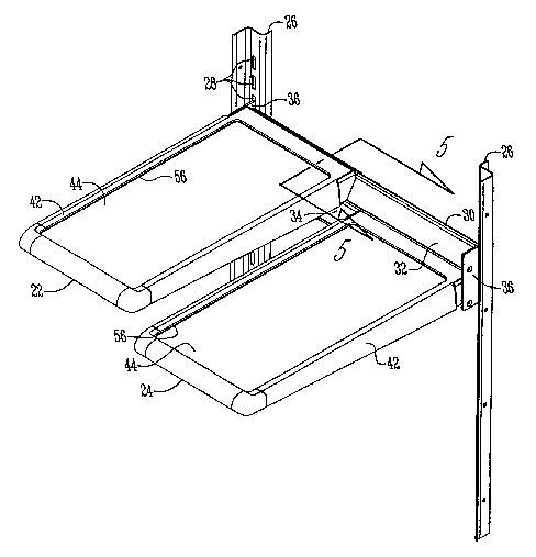
Figure 2 is a perspective view of the shelving wherein the half width shelves
are
laterally and vertically offset with respect to one another, with one shelf
being on the upper
rail and one shelf being on the lower rail.
Figure 3 is a perspective view of the improved shelving wherein the shelves
are
positioned one immediately above the other to provide a tall storage space
adjacent the
shelves, with one shelf on the upper rail and one shelf on the lower rail.
2

CA 02453611 2004-O1-12
WO 03/008884 PCT/US02/22406
Figure 4 is a perspective view showing the improved shelving in lateral side-
by-side
orientation to extend substantially the full width of the food compartment,
with both
shelves mounted on the lower rail.
Figure S is a sectional view taken along lines 5-5 of Figure 2.
Figure 6 is a top plan view showing the unitary construction of the shelf hook
and
frame.
Figure 7 is a view similar to Figure 5 showing an alternative embodiment for
the
rail assembly.
DETAILED DESCRIPTION OF THE INVENTION
A refrigerator 10 is shown in Figure 1 with a door 12 for the fresh food
compartment 14 and a door 16 for the freezer compartment. While the
refrigerator 10 is
shown to be a side-by-side model, it is understood that the refrigerator 10
may have other
configurations wherein the freezer is above or below the fresh food
compartment 14.
The fresh food compartment 14 includes one or more food storage bins 18 and
shelves 20 for the efficient storage of food and drink.
The present invention is directed towards a pair of shelves 22, 24.
Preferably, each
shelf 22, 24 has a width which is approximately one-half the width of the food
compartment 14. As seen in Figures 2-4, a pair of support brackets 26 are
mounted in a
vertical orientation adjacent the back corners of the food compartment 14. The
brackets 26
may be mounted in any convenient fashion, and may be mounted to either the
side walls or
rear wall of the food compartment 14. The brackets 26 include a plurality of
slots 28 for
mounting a rail assembly 30.
More particularly, the rail assembly 30 includes upper and lower horizontally
disposed rails 32, 34, which are closely spaced to one another. The rails 32,
34 are
connected to one another at their opposite ends by end plates 36. The end
plates include a
hook or catch 38 extending rearwardly near the upper edge of the end plates 36
and the pin
40 adjacent the lower edge of the end plates. The catch 38 and pin 40 of each
end plate 36
is adapted to be received in the slots 28 in the respective support brackets
26. Thus, the rail
assembly 30 can be selectively positioned at a desired height along the
brackets 26.

CA 02453611 2004-O1-12
WO 03/008884 PCT/US02/22406
The shelves 22, 24 each have an external frame 42, with a panel 44 mounted
within
the frame 42. Preferably, the external frame 42 is injection molded and the
panel 44 is
made of glass.
A rolled hook 46 extends rearwardly from the rear edge of the internal frame
45, as
shown in Figure 6. Preferably, the hook 46 and internal frame 45 have a
unitary
construction, as shown in Figure 7. Preferably, the hook 46 extends across the
width of
each shelf 22, 24, though multiple spaced apart hooks could also be utilized.
The hooks 46
are adapted to extend over the top edge of either the upper rail 32 or the
lower rail 34 to
engage the back of the rails 32, 34. An optional groove 48 may extend across
the back of
the rails 32, 34 to receive the hook 46, as best seen in Figure 5. The
external frame 42 of
the shelves 22, 24 also includes a downwardly extending leg 50 adapted to
engage the rails
32, 34, such that the shelves 22, 24 cantilever forwardly from the rails 32,
34. The internal
frame 45 may optionally include a metal reinforcement member 52 for the leg
50. As with
the hook 46, preferably the leg SO extends substantially across the width of
each shelf 22,
24, but alternatively separate spaced apart legs can be provided.
Each rail 32, 34 includes a sloped forward surface 54. Therefore, when it is
necessary to remove the shelves 22, 24 for cleaning, for example if there is
spillage on the
shelf, the shelves 22, 24 can be lifted upwardly and rearwardly while being
maintained in a
horizontal position, such that material does not spill from the shelf. The
external frame 42
defines a raised lip 56 extending above the panel 44 so as to prevent liquids
spilled onto
one of the shelves 22, 24 from spilling off the shelf 22, 24.
The shelves 22, 24 can be arranged on the rails 32, 34 in several manners. In
Figure
2, the shelves are side-by-side but vertically offset, with shelf 22 being
mounted on the
upper rail 32, and the shelf 24 being mounted on the lower rail 34. If space
is needed in the
fresh food compartment 14 for a tall item, shelf 24 can be slid laterally
along the rail 34 so
as to be positioned immediately below the shelf 22, as shown in Figure 3.
Thus, the space
previously occupied by shelf 24 is now open to receive a tall object within
the food
compartment 14, without losing any substantial storage space beneath the shelf
22, and
without having to store the shelf 24 somewhere outside the refrigerator 10. It
is understood
that the shelves 22, 24 can slide in either lateral direction along the rails
32, 34, such that
the shelves can be on either the left or right sides of the food compartment
14.
4

CA 02453611 2004-O1-12
WO 03/008884 PCT/US02/22406
The elongated hook 46 and the sloped rail faces 54, 54A enhance distribution
of the
shelf load substantially across the width of the hook and rail faces. The
slope faces 54,
54A also increases the reactive distance for the shelf load, as compared to a
vertical rail of
the same height. Therefore, the shelves 22, 24 can be stacked in a vertical
height of
approximately 3 inches, as shown in Figure 3.
Another shelf arrangement is shown in Figure 4, wherein the shelves 22, 24 are
mounted side-by-side at the same level. It is understood that the shelves 22,
24 can both be
mounted on the lower rail 34, as shown in Figure 4, or can both be mounted on
the upper
rail 32 so as to provide an effective full-width shelf area extending
substantially between
the sidewalk of the refrigerator 10.
An alternative embodiment of the rail assembly is shown in Figure 7, and
includes
elongated metal plates or rails 32A, 34A which are mounted angularly upon the
end plates
36A so as to define a sloped face 54A on each rail 32A, 34A. The mounting of
the shelves
22, 24 upon rails 32A, 34A is the same as described above with respect to
rails 32, 34.
The invention has been shown and described above with the preferred
embodiments, and it is understood that many modifications, substitutions, and
additions
may be made which are within the intended spirit and scope of the invention.
From the
foregoing, it can be seen that the present invention accomplishes at least all
of its stated
objectives.

Representative Drawing
A single figure which represents the drawing illustrating the invention.
Administrative Status

2024-08-01:As part of the Next Generation Patents (NGP) transition, the Canadian Patents Database (CPD) now contains a more detailed Event History, which replicates the Event Log of our new back-office solution.

Please note that "Inactive:" events refers to events no longer in use in our new back-office solution.

For a clearer understanding of the status of the application/patent presented on this page, the site Disclaimer , as well as the definitions for Patent , Event History , Maintenance Fee  and Payment History  should be consulted.

Event History

Description Date
Revocation of Agent Requirements Determined Compliant 2022-02-03
Appointment of Agent Requirements Determined Compliant 2022-02-03
Time Limit for Reversal Expired 2006-07-17
Application Not Reinstated by Deadline 2006-07-17
Inactive: IPC from MCD 2006-03-12
Deemed Abandoned - Failure to Respond to Maintenance Fee Notice 2005-07-15
Letter Sent 2004-08-12
Inactive: Single transfer 2004-07-07
Inactive: Office letter 2004-06-02
Inactive: Single transfer 2004-04-29
Inactive: Courtesy letter - Evidence 2004-03-16
Inactive: Cover page published 2004-03-11
Letter Sent 2004-03-09
Inactive: Acknowledgment of national entry - RFE 2004-03-09
Application Received - PCT 2004-02-06
National Entry Requirements Determined Compliant 2004-01-12
Request for Examination Requirements Determined Compliant 2004-01-12
All Requirements for Examination Determined Compliant 2004-01-12
Application Published (Open to Public Inspection) 2003-01-30

Abandonment History

Abandonment Date Reason Reinstatement Date
2005-07-15

Maintenance Fee

The last payment was received on 2004-06-23

Note : If the full payment has not been received on or before the date indicated, a further fee may be required which may be one of the following

  • the reinstatement fee;
  • the late payment fee; or
  • additional fee to reverse deemed expiry.

Patent fees are adjusted on the 1st of January every year. The amounts above are the current amounts if received by December 31 of the current year.
Please refer to the CIPO Patent Fees web page to see all current fee amounts.

Fee History

Fee Type Anniversary Year Due Date Paid Date
Registration of a document 2004-01-12
Request for examination - standard 2004-01-12
Basic national fee - standard 2004-01-12
MF (application, 2nd anniv.) - standard 02 2004-07-15 2004-06-23
Owners on Record

Note: Records showing the ownership history in alphabetical order.

Current Owners on Record
MAYTAG CORPORATION
Past Owners on Record
FORREST F. WING
JOHN PINK
MICHAEL J. EVELAND
ROGER MIERSEN
TODD E. KNIFFEN
TOM GOSE
Past Owners that do not appear in the "Owners on Record" listing will appear in other documentation within the application.
Documents

To view selected files, please enter reCAPTCHA code :


To view images, click a link in the Document Description column (Temporarily unavailable). To download the documents, select one or more checkboxes in the first column and then click the "Download Selected in PDF format (Zip Archive)" or the "Download Selected as Single PDF" button.

List of published and non-published patent-specific documents on the CPD .

If you have any difficulty accessing content, you can call the Client Service Centre at 1-866-997-1936 or send them an e-mail at CIPO Client Service Centre.

({010=All Documents, 020=As Filed, 030=As Open to Public Inspection, 040=At Issuance, 050=Examination, 060=Incoming Correspondence, 070=Miscellaneous, 080=Outgoing Correspondence, 090=Payment})


Document
Description 
Date
(yyyy-mm-dd) 
Number of pages   Size of Image (KB) 
Abstract 2004-01-11 2 71
Description 2004-01-11 5 233
Claims 2004-01-11 1 44
Representative drawing 2004-01-11 1 18
Drawings 2004-01-11 7 128
Acknowledgement of Request for Examination 2004-03-08 1 176
Reminder of maintenance fee due 2004-03-15 1 109
Notice of National Entry 2004-03-08 1 201
Courtesy - Certificate of registration (related document(s)) 2004-08-11 1 105
Courtesy - Abandonment Letter (Maintenance Fee) 2005-09-11 1 173
PCT 2004-01-11 17 608
Correspondence 2004-03-08 1 26
Correspondence 2004-06-01 1 24
Fees 2004-06-22 1 29