Note: Descriptions are shown in the official language in which they were submitted.
CA 02453660 2004-01-14
WO 03/008756 PCT/EP02/08046
- 1 -
WELLBORE SYSTEM WITH ANNULAR SEAL MEMBER
The present invention relates to a wellbore system
comprising a borehole extending into an earth formation,
a tubular element extending into the borehole whereby a
cylindrical wall surrounds the tubular element in a
manner that an annular space is formed between the
tubular element and the cylindrical wall, and wherein at
least one seal member is arranged in said annular space.
The cylindrical wall can be formed, for example, by the
borehole wall or by another tubular element.
Known seal members are, for example, packers which
are arranged in the borehole to seal an annular space
between a wellbore casing and a production tubing
extending into the borehole. Such packer is radially
deformable between a retracted position in which the
packer is lowered into the borehole, and an expanded
position in which the packer forms a seal. Activation of
the packer can be by mechanical or hydraulic means. A
limitation of the applicability of such packers is that
the seal surfaces have to be well defined.
Another type of annular seal member is formed by a
layer of cement arranged in an annular space between a
wellbore casing and the borehole wall. Although in
general cement provides adequate sealing capability,
there are some inherent drawbacks such as shrinking of
the cement during hardening resulting in de-bonding of
the cement sheath, or cracking of the cement layer after
hardening, for example due to pressure and temperature
shocks during operation of the well.
CA 02453660 2009-03-19
63?93-3968
- 2 -
In view thereof there is a need for an improved
wellbore system which provides adequate sealing of the
annular space formed between a tubular element extending
into the borehole and a cylindrical wall surrounding the
tubular element.
According to one aspect of the present invention,
there is provided a wellbore system, comprising a borehole
extending into an earth formation; a tubular element
extending into the borehole whereby a cylindrical wall
surrounds the tubular element in a manner that an annular
space is formed between the tubular element and the
cylindrical wall; at least one seal member arranged in said
annular space, each seal member being movable between a
retracted mode in which the seal member has a first volume
and an expanded mode in which the seal member has a second
volume larger than the first volume, wherein the seal member
in the expanded mode thereof seals the annular space, and
wherein the seal member includes a material which swells
upon contact with a selected fluid so as to move the seal
member from the retracted mode to the expanded mode thereof,
characterized in that the tubular element has been radially
expanded in the borehole.
By bringing the seal member into contact with the
selected fluid, the seal member swells and thereby becomes
firmly pressed between the tubular element and the
cylindrical wall. As a result the annular space becomes
adequately sealed, even if one or both of the tubular
element and the cylindrical wall are of irregular shape.
Suitably the cylindrical wall is one of the
borehole wall and the wall of a casing extending into the
borehole.
CA 02453660 2009-03-19
63293-3968
- 2a -
The system of the invention can also be used in
applications wherein the cylindrical wall is the wall of
CA 02453660 2004-01-14
WO 03/008756 PCT/EP02/08046
- 3 -
an outer casing arranged in the borehole, and wherein the
tubular element is an inner casing, tubing or liner
arranged in the borehole and extending at least partly
into the outer casing.
To obtain an even better sealing system, it is
preferred that the tubular element has been radially
expanded in the borehole. In such application the seal
member can be, for example, applied to the outer surface
of the tubular element before radial expansion thereof so
as to allow easy installation of the tubular element and
the seal member in the borehole. Thereafter the tubular
element can be radially expanded before or after swelling
of the seal member due to contact with the selected
fluid. However, to reduce the forces needed to expand the
tubular element it is preferred that swelling of the seal
member takes place after expansion of the tubular
element.
Suitably the selected fluid is water or hydrocarbon
fluid contained in the earth formation.
It is preferred that said material of the seal member
includes one of a rubber compound, a thermoset compound
and a thermoplastic compound. The rubber compound is
suitably selected from a thermoset rubber compound and a
thermoplastic rubber compound.
Examples of suitable thermoset rubbers, which swell
when in contact with oil are:
natural rubber, nitrile rubber, hydrogenated nitrile
rubber, acrylate butadiene rubber, poly acrylate rubber,
butyl rubber, brominated butyl rubber, chlorinated butyl
rubber, chlorinated polyethylene, neoprene rubber,
styrene butadiene copolymer rubber, sulphonated
polyethylene, ethylene acrylate rubber, epichlorohydrin
ethylene oxide copolymer, ethylene-propylene-copolymer
CA 02453660 2004-01-14
WO 03/008756 PCT/EP02/08046
- 4 -
(peroxide cross-linked), ethylene-propylene-copolymer
(sulphur cross-linked), ethylene-propylene-diene
terpolymer rubber, ethylene vinyl acetate copolymer,.
fluoro rubbers, fluoro silicone rubber, and silicone
rubbers.
A review of thermoset and thermoplastic rubbers and
their ability to swell in certain fluids such as
hydrocarbon oils can be found in standard reference books
such as `Rubber Technology Handbook', authored by Werner
Hofmann (ISBN 3-446-14895-7, Hanser Verlag Muenchen),
Chapters 2 and 3. Preferably, one would select rubbers
which swell substantially (at least 50 vol%) in
hydrocarbons at typical conditions of temperature and
pressure as encountered in oil or gas wells, but yet
remain integer in a swollen state for enhanced periods of
times (i.e. years). Examples of such rubbers are
ethylene-propylene-copolymer (peroxide cross-linked) also
known as EPDM rubber, ethylene-propylene-copolymer
(sulphur cross-linked) also known as EPDM rubber,
ethylene-propylene-diene terpolymer rubber also known as
EPT rubber, butyl rubber, brominated butyl rubber,
chlorinated butyl rubber, and chlorinated polyethylene.
Examples of suitable materials which swell when in
contact with water are: starch-polyacrylate acid graft
copolymer, polyvinyl alcohol cyclic acid anhydride graft
copolymer, isobutylene maleic anhydride, acrylic acid
type polymers, vinylacetate-acrylate copolymer,
polyethylene oxide polymers, carboxymethyl cellulose type
polymers, starch-polyacrylonitrile graft copolymers and
the like and highly swelling clay minerals such as Sodium
Bentonite (having as main ingredient montmorillonite).
Suitable recipes are for instance disclosed in US
Patent 5,011,875 (Corrosion Resistant Water Expandable
CA 02453660 2004-01-14
WO 03/008756 PCT/EP02/08046
- 5 -
Composition), US Patent 5,290, 844 (Water Swelleable
Water Stop), US Patent 4,590,227 (Water-Swelleable
Elastomer Composition), US Patent 4,740,404 (Waterstop),
US Patent 4,366,284, 4,443,019 and 4,558,875 (all
entitled: `Aqueously-Swelling Water Stopper and a Process
of Stopping Water thereby'). The water swelling elastomer
compositions are commonly referred to as `Waterstops' and
are commercially available under trade names such as
HYDROTITE and SWELLSTOP.
The invention will be described hereinafter in more
detail and by way of example with reference to the
accompanying drawings in which
Fig. 1 schematically shows an embodiment of the
wellbore system of the invention; and
Fig. 2 schematically shows a detail of Fig. 1.
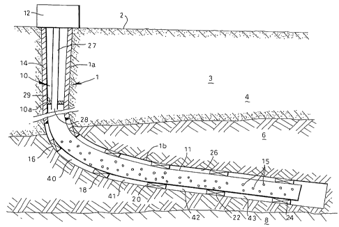
Referring to Fig. 1 there is shown a wellbore system
including a borehole 1 which has been drilled from
surface 2 into an earth formation 3. The borehole 1
penetrates an overburden layer 4 and a reservoir zone 6
containing hydrocarbon oil. A layer 8 containing
formation water is commonly found below the reservoir
zone. The borehole 1 has a substantially vertical upper
section la extending through the.overburden layer 4 and a
substantially horizontal lower section lb extending into
the reservoir zone 6.
A tubular casing string 10 which is formed'of a
number of casing sections (not shown), extends from a
wellhead 12 at surface into the upper borehole
section la. A further tubular casing string 11 is
provided with a plurality of perforations 15 (for sake of
clarity not all perforations have been indicated by a
reference numeral) which provide fluid communication
between the interior of the casing string 11 and the
CA 02453660 2004-01-14
WO 03/008756 PCT/EP02/08046
- 6 -
exterior thereof. Annular seal assemblies 16, 18, 20, 22,
24 are arranged at selected mutual spacings in an annular
space formed 26 formed between the lower casing string 11
and the wall of the lower borehole section lb.
Furthermore, a production tubing 27 extends from the
wellhead 12 into the vertical borehole section la to a
position at or near the transition from the vertical
borehole section la to the horizontal borehole
section lb. The tubing 27 has an open lower end 28, and
is provided*with a seal packer 29 which seals the annular
space between the tubing 27 and the casing string 10.
Referring further to Fig. 2 there is shown seal
assembly 18 in more detail, the other annular seal
assemblies being similar thereto. Annular seal
assembly 18 includes individual seal members 30, 31, 32,
33, 34, each seal member being movable between a
retracted mode in which the seal member has a first
volume and an expanded mode in which the seal member has
a second volume larger than the first volume, whereby the
seal member in the expanded mode thereof seals the
annular space 26. Seal members 30, 32, 34 are made of a
material which swells upon contact with a hydrocarbon oil
so as to move the seal member 30, 32, 34 from the
retracted mode to the expanded mode thereof. Seal_
members 31, 33 are made of a material which swells upon
contact with water so as to move the seal member 31, 33
from the retracted mode to the expanded mode thereof. A
suitable material for seal members 30, 32, 34 is, for
example, EPDM rubber (ethylene-propylene-copolymer,
either sulphur or peroxide cross-linked), EPT rubber
(ethylene-propylene-diene terpolymer rubber), butyl
rubber or a haloginated butyl rubber. A suitable material
for seal members 31, 33 is for example a thermoset or
CA 02453660 2004-01-14
WO 03/008756 PCT/EP02/08046
- 7 -
thermoplast rubber filled with a substantial (60%)
quantity of a water swelleable agent e.g. bentonite, but
any of the `WaterStop' formulations cited above, could be
used.
During normal use, the vertical borehole section la
is drilled and the casing sections of casing string 10
are installed therein as drilling proceeds. Each casing
section is radially expanded in the vertical borehole
section la and conventionally cemented therein by means
of layer of cement 14. Subsequently the horizontal
borehole section lb is drilled and lower casing string 11
is installed therein. Before lowering the lower casing
string 11 into the borehole 1, the annular seal
assemblies 16, 18, 20, 22, 24 are arranged around the
outer surface of the lower casing string 11 at the
indicated mutual spacings, whereby each individual seal
member 30, 31, 32, 33, 34 of the seal assemblies is in
its retracted mode. After installing the lower casing
string 11 into'the lower borehole section lb, the lower
casing string 11 is radially expanded to a diameter
larger than before such that the seal assemblies 16, 18,
20, 22, 24 are not, or only loosely, in contact with the
borehole wall.
When production of hydrocarbon oil starts, a valve
(not shown) at the wellhead 12 is opened and hydrocarbon
oil flows from the reservoir zone 6 into the lower
borehole section lb. The oil flows via the
perforations 15 into the lower casing string 11 and from
there via the production tubing to the wellhead 12 where
the oil is further transported through a pipeline (not
shown) to a suitable production facility (not shown).
As the oil flows into the lower borehole section 1b,
the oil comes into contact with the individual seal
CA 02453660 2004-01-14
WO 03/008756 PCT/EP02/08046
_ 8 -
members of each seal assembly 16, 18, 20, 22, 24. The
seal members 30, 32, 34 thereby swell and, as a result,
move to the expanded mode so as to become firmly pressed
between the lower casing part 10b and the borehole wall.
In this manner each seal assembly seals the annular
space 26 and divides the horizontal borehole section lb
into respective borehole zones 40, 41, 42, 43 whereby
zone 40 is defined between seal assemblies 16 and 18,
zone 41 is defined between seal assemblies 18 and 20,
zone 42 is defined.between seal assemblies 20 and 22, and
zone 43 is defined between seal assemblies 22 and 24.
After some time it can occur that water from the
formation layer 8 enters the horizontal borehole
section lb, for example due to the well-known phenomenon
of water coning. To determine the zone of the borehole
section lb where the water flows into the borehole a
suitable production logging tool is lowered into the
lower casing string 11 and operated. Once the zone of
water entry has been determined, for example zone 42, a
patch is installed in the lower casing string 11, between
seal assemblies 20, 22, so as to close-off the
perforations 15 located between seal assemblies 20, 22. A
suitable patch is, for example, a length of tube (not
shown) which is radially expanded against the inner
surface of lower casing string 11. The patch can be clad
with a water swelling gasket.
Should the seal members 30, 32, 34 of respective seal
assemblies 20, 22 move to their retracted mode due to
discontinued contact with hydrocarbon oil, the presence
of water in zone 42 ensures that the seal members 31, 33
of seal assemblies 20, 22 swell and thereby move to the
expanded mode. It is thus achieved that at least some of
the seal members 30, 31, 32, 33, 34 of seal
CA 02453660 2004-01-14
WO 03/008756 PCT/EP02/08046
- 9 -
assemblies 20, 22 seal the annular space 26, irrespective
whether oil or water is the surrounding medium.
In an alternative embodiment of the system of the
invention, an expandable slotted tubular (EST)(EST is a
trademark) liner can be applied instead of the perforated
lower casing string 11 referred to above. For example, a
liner with overlapping longitudinal slots as described in
US Patent 5366012, could be applied. During radial
expansion of the liner, the metal liner parts in-between
the slots behave as plastic hinges so that the slots
widen and thereby provide fluid communication between the
interior of the liner and the exterior thereof. To
isolate selected zones of the borehole from other zones,
one or more patches in the form of blank casing sections
can be expanded against the inner surface of the slotted
liner. Such blank casing sections are suitably clad with
alternating annular seal members of water and hydrocarbon
swelling elastomers. In this way it is possible to shut
off certain slotted sections of the liner which have
watered out in the course of the life of the well.
In another alternative embodiment of the system of
the invention, an expandable sand screen (ESS)(ESS is a
trademark), such as described in US 5901789, can be
applied instead of the perforated lower casing string 11
referred to above. Again, patches in the form of blank
casing sections (preferably clad with hydrocarbon- and/or
water-swelleable gaskets) can be expanded against the
inner surface of the expandable sand screen to isolate
selected zones. Especially in very long parts of
horizontal or multibranch wells, certain sections'of the
sand screen, which would start producing water ('watered-
out') and/or high ratios of gas ('gassed-out') can be
isolated in this manner. If no corrective measures would
CA 02453660 2004-01-14
WO 03/008756 PCT/EP02/08046
- 10 -
be taken against such undesirable water or gas
production, the well would very rapidly become
uneconomical and its ultimate hydrocarbon fluid recovery
would be significantly reduced.
The ability to shut off watered-out or gassed-out
zones of the weilbore allows the Production Engineer to
significantly defer the abandonment timing of the well
and to maximise the ultimate recovery of the well.
Instead of applying the material which swells upon
contact with hydrocarbon fluid and the material which
swells upon contact with water in separate seal members,
such material can be applied in a single seal member. For
example, the hydrocarbon-swelling ability of an EP(D)M or
EPT rubber can be combined with a water swelling ability
of a suitable filler such as e.g. bentonite in a siTigle
seal member, such that only one type of packing element
with dual functionality is achieved.