Note: Descriptions are shown in the official language in which they were submitted.
CA 02453673 2008-10-29
WO 03/005797 PCT/US02/22528
IMPLANTABLE SEIZURE-SUPPRESSING DEVICE
Field of the Invention
The invention relates generally to treatment of movement disorders and, more
particularly, to intracranial treatment utilizing identification of an
incipient movement
disorder.
Backy-round of the Invention
Movement disorders such as epilepsy and Parkinson's disease have been
estimated to affect some 1-2% of the developed world's population and up to
10% of
people in underdeveloped countries. Currently, approximately 75% of those who
suffer from movement disorders are responsive in some degree to drugs.
However,
undesirable side effects often prevent such treatment.
In addition, drug treatment often imposes a continual effect on brain cells
and
other tissues commonly resulting in the perpetual presence of side effects,
while the
movement disorder episodes, e.g., epileptic seizures, sought to be prevented
occur
much less frequently. Furthermore, patients often develop such high tolerances
for the
drugs administered that they are no longer effective at safe dosages.
Therefore, there
has been a need for movement disorder suppression which avoids the use of
drugs.
Electrical stimulation has been utilized to treat some movement disorders. In
the treatment of epilepsy, studies have been performed in which awake patients
undergoing temporal lobe surgery underwent cortical stimulation. Such
stimulation of
the visual and hearing areas of the brain reproducibly caused the patients to
experience
visual and auditory phenomena. This discovery was made possible by the
identification that certain brain subregions served specific functions, such
as sight,
hearing, touch and movement of the extremities and proved that direct
electrical
stimulation of the brain regions could cause partial reproduction or
suppression of the
functions.
CA 02453673 2004-01-13
WO 03/005797 PCT/US02/22528
As suggested by these results, it is known that certain types of treatment of
specific portions of the brain are able to suppress certain unwanted behavior
which
results from movement disorders. This behavior may include seizures such as
those
suffered by epileptics. However, the studies faced a major problem in that
there was
an inability to precisely electrically stimulate very small volumes of the
brain.
The advent of needle-shaped penetrating depth electrodes helped to overcome
this obstacle faced by electrical stimulation. Depth electrodes can be placed
within
the brain tissue itself, enabling optimal surface contact with elements of the
brain that
are targeted for stimulation. This allowed for safe, chronic electrical
stimulation of
very small discrete volumes of brain.
There have been attempts to provide neurocybernetic prostheses for alleviating
epilepsy and related disorders. United States Patent No. 4,702,254 to Zabara
discloses
a prosthesis which comprises a miniature electronic integrated circuit with an
output
which augments appropriate brain neural discharge to control convulsions or
seizures.
The Zabara device uses neural spectral discrimination by tuning the electrical
current
of the prosthesis to the electrochemical properties of a specific group of
inhibitory
nerves that affect the reticular system of the brain. Certain electrical
parameters of the
prosthesis must be selected based on the electrochemical properties of the
nerves
desired to be activated. The patent teaches that the optimal site for the
application of
the prosthesis is on the vagus nerve.
While the electrical stimulation of brain tissue has been somewhat effective
in
the treatment of migraines, epilepsy and other neurological problems, patients
often
experience diminishing returns with such treatment. Furthermore, because each
patient reacts differently to electrical stimulation, substantial time must be
spent to
determine the specific amplitude, frequency, pulse width, stimulation
duration, etc.
which may result in effective treatment. In addition, such parameters often
require
continual adjustment in order to remain effective.
In treatment, electrical stimulation has been used with the recording and
analysis of electrical changes in brain activity to predict the occurrence of
epileptic
seizures. The time of onset of such seizures is often predictable by neural
discharge
monitoring, even when the exact causal nature of precipitating dysfunction is
not
-2-
CA 02453673 2004-01-13
WO 03/005797 PCT/US02/22528
understood. United States Patent No. 5,995,868 to Dorfineister discloses the
use of
electrodes to obtain signals representative of current brain activity and a
signal
processor for continuous monitoring and analysis of these electrical signals
in order to
identify important changes or the appearance of precursors predictive of an
impending
change. Dorfineister mainly discusses the quick identification of the onset of
a
seizure; cooling a portion of the brain in response to such identification is
mentioned,
but he does not discuss how such cooling could be performed.
At the time of Dorfmeister, the treatment of various disorders of and injuries
to
the brain utilizing the transfer of heat away from (cooling) the brain was
well known
in the medical arts and was often performed using the external application of
cold
fluids, housed chemicals involved in endothermic reactions or other
refrigerants.
Other methods of cooling include the external cooling of blood which is
recirculated
through the body.
United States Patent Nos. 4,750,493 and 4,920,963 to Brader are directed to a
method for cooling the extracranial area during emergency care of cardiac
arrest or
extreme shock in order to induce vasoconstriction and intracranial
hypothermia.
These inventions are implemented by a topical cold pack or watertight shroud
which
cannot specifically cool a targeted portion in the brain. United States Patent
No.
5,383,854 to Safar et al. is directed to a cardiopulmonary bypass apparatus
which is
able to cool the blood. This device cannot specifically cool a target portion
in the
brain either.
United States Patent No. 6,188,930 B l to Carson is directed to a method for
heating the hypothalamus which utilizes a device for cooling the surrounding
body
tissues. This device is not implanted, but is used temporarily during or
preceding
surgery. The patent discloses cooling through the circulation of a liquid or
gas coolant
through a catheter. Chronic cooling of a targeted portion in the brain is not
disclosed.
United States Patent No. 6,090,132 to Fox is directed to a method of inducing
hypothermia in a mammal. This invention applies heat to the hypothalamus in
order
to effect a compensatory cooling response, thereby lowering body temperature.
The
patent discloses the direct application of heat to the hypothalamus for a
temporary
-3-
CA 02453673 2008-10-29
WO 03/005797 PCT/US02/22528
cooling effect. The patent does not disclose chronic treatment using an
implanted
device, nor the cooling of a specific portion.
United States Patent No. 5,215,086 to Terry employs a neurostimulator to
selectively apply electrical therapy to treat migraines. The neurostimulator
delivers
pulses of electricity of a specific pulse width and amplitude to the patient's
vagus
nerve in order to stimulate nerve fibers and either synchronize or
desynchronize the
EEG and control migraines.
United States Patent Nos. 5,843,093 and 6,129,685 to Howard relate to the
selective treatment of neurons within the brain with particular emphasis on
the
treatment of Parkinson's through pallidotomy and on the regulation of a
patient's
appetite through electrical discharges to the hypothalamus. Both of these
patents
disclose the inactivation of neurons through the use of a cryogenic device,
though they
do not teach what the cryogenic device could be or how it might be safely
disposed
within the brain.
Despite the Dorfmeister and Howard disclosures, it has not yet been possible,
upon recognition of an incipient movement disorder, to effectively and
immediately
cool a localized area in the brain with an implanted device episode which can
avoid
undue risk or injury to the brain. An implanted device for thermal treatment
of
movement disorders episodes which addresses the problems of known treatments
would be an important advance in the art.
Obiects of the Invention
It is an object of the invention to provide an implanted device for thermal
treatment of movement disorders overcoming some of the problems and
shortcomings
of prior art devices for suppressing movement disorders.
-4-
CA 02453673 2008-10-29
WO 03/00-5797 PCT/US02/22525
Summary of the Invention
The invention provides an implantable seizure-suppressing device comprising at
least one temperature-contact adapted to be positioned at a targeted portion
in the brain,
and a heat-transfer operator adapted to be positioned away from the targeted
portion and
thermally coupled to the temperature-contact, whereby heat is withdrawn from
the
targeted portion upon activation of the heat-transfer operator.
The device is intended to prevent or suppress movement disorder episodes, such
as epileptic seizures, through the transfer of heat away from a targeted
portion in the
brain that has been previously identified as being associated with movement
disorder
episodes in the patient.
20
30
-5-
CA 02453673 2004-01-13
WO 03/005797 PCT/US02/22528
The preferred embodiment of the apparatus of this invention provides for the
rapid transfer of heat away from (cooling of) a selected portion, or volume,
in a
patient's brain upon detection of a physiological symptom of an incipient
movement
disorder episode. This targeted portion of the brain may be a very small,
point-like
volume. Such physiological symptoms may be particular to the patient, and may
evolve during the patient's lifetime. The transfer of heat automatically
ceases upon
the attainment of sufficient cooling at the targeted portion. Such sufficient
cooling
may be determined by the temperature at the targeted portion, the duration of
the heat
transfer which may be programmed in a controller, the subsidence of
physiological
symptoms or the presence of physiological evidence that the episode has been
suppressed.
The preferred device comprises at least one temperature-contact positioned at
a
targeted portion in the brain. The temperature-contact is thermally coupled to
the cold
junction of a heat-transfer operator such that heat is compelled to flow from
the
temperature-contact into the cold junction to affect cooling at the targeted
portion.
The temperature-contact can be positioned adjacent to the targeted portion, or
simply
near the targeted portion, so that heat transfer by the temperature-contact
effectively
cools the targeted portion.
The preferred heat-transfer operator is a Peltier cooler or a thermal-electric
cooler. Such heat-transfer operators pass electricity through junctions
between
dissimilar metals. The atoms of the dissimilar metals have a difference in
energy
levels which results in a step between energy levels at each of the metals'
junctions.
As electricity is passed through the metals, the electrons of the metal with
the lower
energy level pass the first step as they flow to the metal with the higher
energy level.
In order to pass this step and continue the circuit, the electrons must absorb
heat
energy which causes the metal at the first junction to cool. At the opposite
junction,
where electrons travel from a high energy level to a low energy level they
give off
energy which results in an increase in temperature at that junction.
In the context of this application, Peltier cooler refers to a system wherein
pairs of dissimilar materials are joined at two junctions which are separated
by a
substantial length. For instance, for each pair the cold junction could be
positioned in
-6-
CA 02453673 2004-01-13
WO 03/005797 PCT/US02/22528
the brain and the hot junction could be positioned in the abdomen. The
dissimilar
materials may extend to each junction forming a circuit or loop. The
dissimilar
materials may also be separately connected to other conductors such that the
circuit or
loop is comprised of a cold junction of dissimilar first and second materials,
a hot
junction of dissimilar first and second materials, a conductor connecting the
ends of
the first material and a conductor connecting the ends of the second material.
Thermal-electric cooler refers to a system wherein the cold and hot junctions
are not separated by a substantial length. For instance, the cold junction of
the
thermal-electric cooler may be positioned on the surface of the brain and the
hot
junction could be positioned on a surface in substantial conformity with the
external
surface of the skull. While in principle a single piece of semiconducting
material can
be used in a thermal-electric cooler, connection of multiple semiconducting
materials
in series is preferred to avoid the high current requirement of the single
element.
As stated above, the Peltier cooler includes at least one circuit or loop of
dissimilar materials, preferably semiconducting materials, which are connected
at two
junctions. The Peltier cooler is preferably implanted in the patient so that
its cold
junction is adjacent to the temperature-contact and its hot junction is
located away
from the brain, preferably in the torso. The hot junction is most preferably
located
adjacent to, and thermally coupled to, a titanium housing which acts to
dissipate heat.
The Peltier cooler circuit or loop which extends between the two junctions is
electrically insulated and preferably implanted such that it travels from the
cold
junction at the temperature-contact, out of the skull, down the neck and into
the torso.
In the preferred embodiment utilizing the Peltier cooler, the temperature-
contact is preferably located on the distal end of a depth-electrode type
probe which is
implanted in the patient's brain. The cold junction of the Peltier cooler is
connected
to the temperature-contact in the brain. The Peltier circuit or loop extends
out of the
skull through the proximate end of the probe, down the neck and into the
abdomen
where the hot junction can transfer heat to another device, such as a titanium
housing
or other metal enclosure, or otherwise allow heat to safely dissipate into the
body.
For the Peltier cooler, the preferred temperature-contact is a gold or
platinum
foil or collar which preferably encircles a portion of the distal end of the
probe. The
-7-
CA 02453673 2004-01-13
WO 03/005797 PCT/US02/22528
temperature-contact must be an extremely thermally conductive material which
is
harmless to the surrounding brain tissue.
In the alternative embodiment using a thermal-electric cooler, the temperature-
contact is a gold or platinum foil or collar which has a surface which
corresponds to
the surface of the brain. The temperature-contact is preferably implanted in
the
patient adjacent to the skull.
The temperature-contact is connected, or thermally coupled, to the cold
junction of the thermal-electric cooler. The temperature-contact is preferably
located
on the face of the cold junction. A portion of the skull can be removed so
that the
temperature-contact can be placed adjacent to the brain and the skull with the
thermal-
electric cooler directly adjacent to the skull. The thermal-electric cooler
can be
positioned in the void created when a portion of the skull was removed such
that an
observer of the patient could not easily perceive the implanted device.
Whether utilizing a Peltier cooler or a thermal-electric cooler as a heat-
transfer
operator, the heat-transfer operator is electrically connected to an implanted
power
source which supplies a current through the heat-transfer operator to affect
heat
transfer. The power source operates efficiently by powering off the heat-
transfer
operator supply when heat transfer is not needed. When heat transfer is
desired, the
power source can be activated to supply a DC current to the heat-transfer
operator
which will, in turn, activate heat transfer from the targeted portion through
the
temperature-contact to the cold junction of the heat-transfer operator.
It is contemplated that the power source may be switched on or activated
automatically or remotely by a person. The power source preferably provides
power
from an implanted battery which holds sufficient power so that once implanted,
further operations to recharge the battery, or install a new battery, are not
needed for
an extended period of time, perhaps for as long as the life of the patient.
The power source is preferably implanted in the patient away from the brain,
most preferably in the patient's torso. The power source can located within a
titanium
housing or other metal enclosure which may provide electrical grounding.
To allow for automatic activation of the heat-transfer operator, sensing-
contacts are utilized to detect a physiological symptom of an incipient
movement
-8-
CA 02453673 2004-01-13
WO 03/005797 PCT/US02/22528
disorder episode. The sensing-contacts are preferably positioned in the brain
at a
location which has been determined to be a site at which symptoms of impending
movement disorder episodes may be detected and measured. The physiological
symptoms detected by the sensing-contact can be electrical, electrochemical,
chemical, optical or blood flow changes within the brain or other symptoms.
Such electrical and electrochemical symptoms can be changes in the patient's
EEG, changes in the patient's intracellular EEG or the like which are
recognized as
precursors of episodes. These electrical and electrochemical symptoms are
often
related to intracellular gate changes. Such electrochemical and chemical
symptoms
can be the presence or change in amount of certain biogenic chemicals present
near
the sensing-contact, particularly neurotransmitters such as amines, amine
metabolites,
ascorbic acid, amino acids and neuropeptides or dopamine, glutamate,
aspartate,
seratonin or the receptors, metabolites, precursors, agonists, antagonists or
related
enzymes of such chemicals or sodium, potassium or chloride ions or nitrous
oxide.
The sensing-contacts may be micro sensing-contacts which have surfaces with
diameters of about 25 microns. The sensing-contacts can also be macro sensing-
contacts which are cylinder type collars with lengths of about 2.5 millimeters
and
diameters of about 1.1 millimeters. Sensing-contacts are preferably gold or
platinum
though, as is recognized in the art, any conductive corrosion-resistant and
non-toxic
material may be used.
The sensing-contacts may be micro-circuit or nano-circuit sensors which are
able to measure electrical currents generated through the circuits in response
to an
imposed voltage signal and/or reduction/oxidation reactions of chemical
species at the
circuit. Such circuits are known in the electrical arts and are produced using
microlithography.
The sensing-contact may also be an optical sensor which is able to determine
the concentrations of substances, chemical changes or cerebral blood flow
rates.
Optical sensors are preferably positioned at the tip of the depth electrode so
that the
exposed optical sensor projects from the electrode without increasing the
diameter or
thickness of the implanted device.
-9-
CA 02453673 2004-01-13
WO 03/005797 PCT/US02/22528
In the preferred embodiment utilizing the Peltier cooler the sensing-contacts
are preferably located on the same probe as the temperature-contact. This
construction allows for efficient implantation and removal if necessary due to
unanticipated problems in the patient.
When using a Peltier cooler, the sensing-contacts are connected to sensing
circuitry so that, upon detection of a physiological symptom of an incipient
seizure,
the sensing circuitry activates the supply of current to the heat-transfer
operator and
heat transfer is started, enabling the cooling of the targeted portion and
suppression of
the movement disorder episode. The sensing-contacts are preferably connected
to the
sensing circuitry through the distal end of the probe. The connection between
the
sensing-contacts and the sensing circuitry preferably runs alongside the
Peltier cooler
circuit or loop in order to minimize invasiveness.
In the preferred embodiment utilizing the thermal-electric cooler the sensing-
contacts do not need to be located on a probe. Instead the sensing-contacts
could be
located on the face of the cold junction of the thermal-electric cooler or on
the
temperature contact itself. The invention also provides for the placement of
the
sensing-contacts on a probe of the depth-electrode or flat-electrode type.
When using
a depth-electrode type probe, the sensing-contacts are implanted into the
brain. When
using a flat-electrode type probe, the sensing-contacts are implanted beneath
the skull
on the surface of the brain.
When using a thermal-electric cooler, the sensing-contacts are connected to
sensing circuitry so that, upon detection of a physiological symptom of an
incipient
seizure, the sensing circuitry activates the supply of current to the heat-
transfer
operator and heat transfer is started, enabling the cooling of the targeted
portion and
suppression of the movement disorder episode. The sensing-contacts can be
connected to the sensing circuitry through the distal end of the probe, or
simply
around the exterior of the thermal-electric cooler if no probe is used. The
connection
between the sensing-contacts and the sensing circuitry preferably runs
alongside the
connection between the thermal-electric cooler and the power source in order
to
minimize invasiveness.
-10-
CA 02453673 2004-01-13
WO 03/005797 PCT/US02/22528
To provide for the automatic cessation of heat transfer in either embodiment,
the sensing-contacts are able to signal the sensing circuitry to cease supply
of power to
the heat-transfer operator upon the achieving sufficient cooling. Sufficient
cooling is
achieved by the attairunent of a predetermined temperature at the targeted
portion,
after heat transfer for a programmed period of time, after attainment of a
predetermined temperature for a programmed period of time, after the
subsidence of
physiological symptoms or upon the sensing of physiological indications of the
suppression of the movement disorder episode.
The period of time necessary for sufficient cooling may be programmed into
the device, preferably into the sensing circuitry, before implantation or may
be
programmed by a physician, the patient or another person via telemetry or
other
remote means after implantation.
The temperature at the targeted portion may be determined by a thermocouple
or other temperature detection means located near the targeted portion. The
thermocouple or temperature detection means operates to measure the
temperature of
the targeted portion of the brain so that sufficient cooling may be
ascertained or
excessive cooling may be avoided. The thermocouple or temperature detection
means
is preferably located on the implanted probe or on the surface of the
temperature-
contact or cold junction of the thermal-electric cooler. The thermocouple or
other
temperature detection means is preferably connected to the sensing circuitry
through
the connection between the sensing-contacts and the sensing circuitry (sensing-
contacts-sensing circuitry connection).
The sensing-contacts are powered by the power source through the connection
between the sensing-contacts and the sensing circuitry (sensing-contact-
sensing
circuitry connection). The power source contains such sufficient energy that
its
replacement or recharging is not necessary for an extended period of time,
perhaps as
long as the patient's life, but at least about 3 years. The power source does
not
completely power off upon the sufficient cooling of the targeted portion.
Rather, the
power source continues to supply power to the sensing-contacts so that the
sensing-
contacts are able to detect the symptoms of the next movement disorder
episode. The
power source can be constructed so as to have a constant power component and a
-11-
CA 02453673 2004-01-13
WO 03/005797 PCT/US02/22528
variable power component. The constant power component providing power to the
sensing-contacts and the variable power component supplying a DC current to
the
heat-transfer operator to enable heat transfer.
The power source is preferably implanted in the patient away from the brain in
a less sensitive area of the body. Such areas may be in the patient's axilla
or
abdomen, outside the skull, or in place of a portion of the skull which is
removed.
The power source is preferably enclosed in a titanium housing or other metal
enclosure.
The titanium housing or metal enclosure can be used as an electrical ground
for the electrical components of the device, such as the power source, sensing
circuitry
and heat-transfer operator. However, these electrical components may be
otherwise
grounded in the body. The titanium housing or metal enclosure can also be used
as a
heat sink or heat dissipater. The relatively large surface area of the housing
and its
location in a less heat-sensitive area of the body enable it to release heat
efficiently.
In the embodiment of the invention utilizing manual activation of heat
transfer
the implantation of sensing-contacts and sensing-circuitry is not necessary.
Rather,
the power source can be turned on or activated by a person upon the sensing of
physiological symptoms of a movement disorder episode. Because the power
source
does not need to supply power to sensing-contacts, the power source can be
completely powered off between episodes.
The physiological symptoms are typically particular to the patient. Such
symptoms can be the aura preceding an epileptic seizure. The aura is the
period of
time before the onset of a seizure when the patient experiences sensations or
acts in a
manner particular to an incipient seizure. Such sensations may be a stomach
ache,
photosensitivity or any other feeling which the patient recognizes as a
precursor to a
seizure. The patient may act in a way that others around them recognize as
signaling
an incipient seizure. These acts can include staring into space without
reacting to the
immediate surroundings or slowing down in speech or motion. In addition, an
animal
such as a dog may sense the incipient episode and react in a manner which is
recognizable as being indicative of incipient episodes.
-12-
CA 02453673 2004-01-13
WO 03/005797 PCT/US02/22528
It is also provided that physiological symptoms on the patient's skin may be
detected by a sensor worn by the patient. Upon detection of a symptom, the
sensor is
able to signal an alert, either audibly, through vibration or otherwise as is
known in
the art. The alert notifies the patient or another person to switch on the
variable power
source, or otherwise activate the transfer of heat away from the targeted
portion. Such
a sensor can be worn by the patient, for instance, on the inside of the
patient's
watchband. The sensor is preferably able to detect chemical changes on the
skin's
surface.
It is provided that upon identification of physiological symptoms of a
movement disorder episode, the patient or another person may manually switch
on the
variable power source to activate heat transfer. The switching on process may
include
telemetry or other remote activation systems as are known in the art.
The manual embodiment is also able to utilize automatic cessation of heat
transfer. Automatic cessation occurs upon reaching sufficient cooling of the
targeted
area. Sufficient cooling is achieved by the attainment of a predetermined
temperature
at the targeted portion or after heat transfer for a programmed period of
time.
Finally, it is provided that the patient or another person may turn on the
variable power source, or otherwise activate the heat transfer operator
without the
detection of a physiological symptom. Instead, such activation may be a
prophylactic
measure taken before the patient performs an activity during which an
occurrence of a
seizure would jeopardize the patient's safety. Such an activity may be driving
a car or
operating machinery. The heat transfer in such a situation would preferably
occur for
as long as the activity lasted to ensure that no movement disorder episodes
occurred.
Such prophylactic use may demand a great deal of energy and, therefore, may
shorten
the length of use of the power variable power source.
It is also contemplated that the heat-transfer operator may be another device
or
system which absorbs heat from a specific predetermined area. Such a device
could
include a housing containing a site for endothermic chemical reactions and
connected
to thermal conveyers such that the thermal conveyers transfer heat from their
extremities, located at the targeted portion, to the site. Such heat transfer
can be
-13-
CA 02453673 2008-10-29
WO 03/005797 PCT/US02/22528
accomplished through convection of fluids or conduction. The thermal conveyer
must
be well-insulated to allow for effective heat transfer.
Brief Description of the Drawintas
FIGURES 1 and lA are schematic representations of an implanted thermal
transfer device constructed in accordance with the principles of the present
invention
and utilizing a Peltier cooler and manual activation of heat transfer.
FIGURES 2 and 2A are schematic representations of an implanted thermal
transfer device constructed in accordance with the principles of the present
invention
and utilizing a Peltier cooler and optical sensing of symptoms with fiber
optic
circuitry.
FIGURES 3 and 3A are schematic representations of an implanted thermal
transfer device constructed in accordance with the principles of the present
invention
and utilizing a Peltier cooler and electrical, electrochemical or chemical
sensors with
electrical circuitry and a thermocouple.
FIGURES 4, 4A and 4B are schematic representations of an implanted thermal
transfer device constructed in accordance with the principles of the present
invention
and utilizing a thermal-electric cooler and manual activation of heat
transfer.
FIGURES 5, 5A and 5B are schematic representations of an implanted thermal
transfer device constructed in accordance with the principles of the present
invention
and utilizing a thennal-electric cooler and optical sensing of symptoms with
fiber
optic circuitry. ,
FIGURES 6, 6A and 6B are schematic representations of an implanted thermal
transfer device constructed in accordance with the principles of the present
invention
and utilizing a thermal-electric cooler and electrical, electrochemical or
chemical
sensors with electrical circuitry.
Detailed Description of Preferred Embodiments
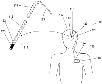
Referring to FIGURES 1 and 1 A, details of the implanted thermal transfer
device, utilizing a Peltier cooler and manual activation thereof, for
treatment of
movement disorder episodes will be set forth. The thermal transfer device 110
-14-
CA 02453673 2004-01-13
WO 03/005797 PCT/US02/22528
requires the positioning of a temperature-contact 120 at a targeted portion
114 in the
brain 112. Temperature-contact 120 is located at the distal end 117 of a probe
118
and is preferably a gold or platinum collar as is known in the art. Probe 118
is
inserted into brain 112 during implantation surgery. Probe 118 is preferably a
flexible
member with a thickness of about 5 millimeters or less.
The cold junction 122 of a Peltier cooler is thermally coupled to temperature-
contact 120 so that it is capable of transferring heat away from temperature-
contact
120 thus cooling targeted portion 114. Cold junction 122 and hot junction 124
are
well-insulated so that heat is not absorbed from or by any tissue surrounding
them.
Peltier cooler circuit 123 preferably passes through the proximate end 119 of
probe
118 and along the outside of the patient's skull through the patient's neck
towards the
patient's axilla until it reaches its hot junction 124. Hot junction 124
releases heat
which is able to safely dissipate into the body. Such safe dissipation is
facilitated by
thermally coupling the hot junction 124 to housing 140 which is able to
efficiently
dissipate heat. Housing 140 is preferably a titanium enclosure.
Housing 140 is depicted as being mounted near the patient's axilla though it
could be positioned farther from the brain in the patient's abdomen. Peltier
cooler
circuit 123 is connected to a power source 136 which provides an electric
current to
Peltier cooler circuit 123 when heat transfer is desired. Power source 136
typically
comprises a long-lasting battery or other energy store and is preferably
located within
housing 140. The passage of the DC electric current through Peltier cooler
circuit 123
results in the absorption of heat at cold junction 122, which results in
absorption of
heat by temperature-contact 120. Peltier cooler circuit 123 is preferably
comprised of
multiple pairs of dissimilar materials, preferably metals or semi-conducting
materials,
connected at cold junction 122 and hot junction 124.
Heat is transferred from cold junction 122 to hot junction 124 as long as an
electric current passes through Peltier cooler circuit 123. When power source
136
ceases to provide power to Peltier cooler circuit 123, heat is no longer
absorbed and
the temperature of targeted portion 114 and temperature-contact 120 slowly
return to
normal body temperature.
-15-
CA 02453673 2004-01-13
WO 03/005797 PCT/US02/22528
Power source 136 is switched on or activated by the patient or another person
in order to activate heat transfer. Power source 136 is switched on via
telemetry or
other remote methods. Typically, power source 136 is activated in response to
the
detection of a physiological symptom of an incipient movement disorder
episode,
though power source 136 can be activated as a prophylactic measure to prevent
movement disorder episodes when the patient is particularly vulnerable to them
or
when their occurrence would endanger the patient.
The physiological symptoms may be detected by the patient, another person, or
even by an animal, or most preferably by a sensor worn by the patient. The
patient
may recognize symptoms which coincide with the aura preceding the onset of a
movement disorder episode. Typically during the aura the patient experiences
sensations or acts in a particular manner which is indicative of an oncoming
episode.
The sensations may be a stomach ache, photosensitivity or any other feeling
which the
patient recognizes as a precursor to a seizure. The patient may recognize his
own
behavior as foretelling an oncoming episode or another person may identify
such
behavior. The behavior may include staring into space without reaction to the
immediate surroundings, slowing down in speech or motion or other abnormal
acts.
An animal such as a dog may also sense oncoming episodes and alert the patient
through its own particular behavior. Finally, a sensor worn on the patient's
body may
detect chemical changes on the patient's skin which are indicative of
incipient
episodes and alert the patient through a audible or vibrational alarm.
Power source 136 ceases to supply current to Peltier cooler circuit 123 when
targeted portion 114 is sufficiently cooled. Sufficient cooling can be defined
to occur
when targeted portion 114 reaches a certain temperature or when heat transfer
has
occurred for a predetermined period of time. The predetermined period of time
can be
programmed before implantation, or after implantation via telemetry or other
remote
means, preferably by a physician.
Referring to FIGURES 2 and 2A, details of the implanted thermal transfer
device, utilizing a Peltier cooler and automatic activation thereof, for
treatment of
movement disorder episodes will be set forth. The thermal transfer device 210
requires the positioning of a temperature-contact 220 at a targeted portion
214 in the
-16-
CA 02453673 2004-01-13
WO 03/005797 PCT/US02/22528
brain 212. Temperature-contact 220 is located at the distal end 217 of a probe
218
and is preferably a gold or platinum collar as is known in the art. Probe 218
is
inserted into brain 212 during implantation surgery. Probe 218 is preferably a
flexible
member with a thickness of about 5 millimeters or less.
Located at the tip of probe 218 is a sensing-contact which is an optical
sensor
230. The optical sensor 230 is capable of measuring chemical changes, optical
changes or cerebral blood flow changes. Optical sensor 230 may be coated with
a
material which is sensitive to the measured chemical conditions at the
targeted portion
214 or optical sensor 230 may be polished such that it is sensitive to optical
conditions
or blood flow changes at the targeted portion 214.
Sensing-contact 230 is connected to sensing circuitry or controller 234 by
sensing-contact-sensing circuitry connection 244 which is fiber optic. Sensing
circuitry 234 is positioned in housing 240 which is a titanium enclosure.
Sensing
circuitry can be grounded to housing 240 or may be grounded elsewhere.
The cold junction 222 of a Peltier cooler is thermally coupled to temperature-
contact 220 so that it is capable of transferring heat away from temperature-
contact
220 thus cooling targeted portion 214. Cold junction 222 and hot junction 224
are
well-insulated so that heat is not absorbed from or by any tissue surrounding
them.
Peltier cooler circuit 223 preferably passes through the proximate end 219 of
probe
218 and along the outside of the patient's skull through the patient's neck
towards the
patient's axilla until it reaches its hot junction 224. Hot junction 224
releases heat
which is able to safely dissipate into the body. Such safe dissipation is
facilitated by
thermally coupling the hot junction 224 to housing 240 which is able to
efficiently
dissipate heat. Housing 240 is preferably a titanium enclosure.
Housing 240 is depicted as being mounted near the patient's axilla though it
could be positioned farther from the brain in the patient's abdomen. Peltier
cooler
circuit 223 is connected to a power source 236 which provides an electric
current to
Peltier cooler circuit 223 when heat transfer is desired. Power source 236
typically
comprises a long-lasting battery or other energy store and is preferably
located within
housing 240. The passage of the DC electric current through Peltier cooler
circuit 223
results in the absorption of heat at cold junction 222, which results in
absorption of
-17-
CA 02453673 2004-01-13
WO 03/005797 PCT/US02/22528
heat by temperature-contact 220. Peltier cooler circuit 223 is preferably
comprised of
multiple pairs of dissimilar materials, preferably metals or semi-conducting
materials,
connected at cold junction 222 and hot junction 224.
Heat is transferred from cold junction 222 to hot junction 224 as long as an
electric current passes through Peltier cooler circuit 223. When power source
236
ceases to provide power to Peltier cooler circuit 223, heat is no longer
absorbed and
the temperature of targeted portion 214 and temperature-contact 220 slowly
return to
normal body temperature.
Symptoms of incipient seizures are measured as either chemical, optical or
cerebral blood flow changes in the brain by the sensing-contacts 230. Upon
identification of such symptoms, sensing/activation circuitry 234 activates
power
source 236 to supply DC current to the Peltier cooler circuit 223. As DC
current is
passed through Peltier cooler circuit 223, cold junction 222 absorbs heat from
temperature-contact 220 which, in turn, absorbs heat from targeted point 214.
Heat is
released from hot junction 224 into housing 240 where it safely dissipates
into the
body.
Such heat transfer can occur for a programmed period of time controlled by
sensing/activation circuitry 234, until a predetermined temperature is reached
in
targeted portion 214 or until sensing-contacts 230 no longer detect symptoms
or
otherwise detect subsidence of the movement disorder episode.
Referring to FIGURES 3 and 3A, details of the implanted thermal transfer
device, utilizing a Peltier cooler and automatic activation thereof, for
treatment of
movement disorder episodes will be set forth. The thermal transfer device 310
requires the positioning of a temperature-contact 320 at a targeted portion
314 in the
brain 312. Temperature-contact 320 is located at the distal end 317 of a probe
318
and is preferably a gold or platinum collar as is known in the art. Probe 318
is
inserted into brain 312 during implantation surgery. Probe 318 is preferably a
flexible
member with a thickness of about 5 millimeters or less.
Located on the distal end 317 of probe 318 is at least one sensing-contact 330
which may be a gold or platinum contact capable of measuring electrical or
electrochemical changes or may be micro-circuits or nano-circuits capable of
-18-
CA 02453673 2004-01-13
WO 03/005797 PCT/US02/22528
measuring electrochemical or chemical changes. Such micro- or nano-circuits
are
known in the art of electrical circuitry and are typically fabricated using
microlithography such that they are able to measure electrochemical or
chemical
changes at the level of neurons.
Sensing-contact 330 is connected to sensing circuitry or controller 334 by
sensing-contact-sensing circuitry connection 344. Sensing circuitry 334 is
positioned
in housing 340 which is a titanium enclosure. Sensing circuitry can be
grounded to
housing 340 or may be grounded elsewhere.
The cold junction 322 of a Peltier cooler is thermally coupled to temperature-
contact 320 so that it is capable of transferring heat away from temperature-
contact
320 thus cooling targeted portion 314. Cold junction 322 and hot junction 324
are
well-insulated so that heat is not absorbed from or by any tissue surrounding
them.
Peltier cooler circuit 323 preferably passes through the proximate end 319 of
probe
318 and along the outside of the patient's skull through the patient's neck
towards the
patient's axilla until it reaches its hot junction 324. Hot junction 324
releases heat
which is able to safely dissipate into the body. Such safe dissipation is
facilitated by
thermally coupling the hot junction 324 to housing 340 which is able to
efficiently
dissipate heat. Housing 340 is preferably a titanium enclosure.
Housing 340 is depicted as being mounted near the patient's axilla though it
could be positioned farther from the brain in the patient's abdomen. Peltier
cooler
circuit 323 is connected to a power source 336 which provides an electric
current to
Peltier cooler circuit 323 when heat transfer is desired. Power source 336
typically
comprises a long-lasting battery or other energy store and is preferably
located within
housing 340. The passage of the DC electric current through Peltier cooler
circuit 323
results in the absorption of heat at cold junction 322, which results in
absorption of
heat by temperature-contact 320. Peltier cooler circuit 323 is preferably
comprised of
multiple pairs of dissimilar materials, preferably metals or semi-conducting
materials,
connected at cold junction 322 and hot junction 324.
Heat is transferred from cold junction 322 to hot junction 324 as long as an
electric current passes through Peltier cooler circuit 323. When power source
336
ceases to provide power to Peltier cooler circuit 323, heat is no longer
absorbed and
-19-
CA 02453673 2004-01-13
WO 03/005797 PCT/US02/22528
the temperature of targeted portion 314 and temperature-contact 320 slowly
return to
normal body temperature.
Symptoms of incipient seizures are measured as either electrical,
electrochemical or chemical changes in the brain by the sensing-contacts 330.
Upon
identification of such symptoms, sensing/activation circuitry 334 activates
power
source 336 to supply DC current to the Peltier cooler circuit 323. As DC
current is
passed through Peltier cooler circuit 323, cold junction 322 absorbs heat from
temperature-contact 320 which, in turn, absorbs heat from targeted point 314.
Heat is
released from hot junction 324 into housing 340 where it safely dissipates
into the
body.
Such heat transfer can occur for a programmed period of time controlled by
sensing/activation circuitry 334, until a predetermined temperature is reached
in
targeted portion 314 or until sensing-contacts 330 no longer detect symptoms
or
otherwise detect subsidence of the movement disorder episode.
The temperature at targeted portion 314 can be measured by thermocouple or
other temperature detection device 316. Thermocouple 316 can be positioned on
probe 318 and is connected to sensing-contact-sensing circuitry connection 344
such
that the temperature at targeted portion 314 can be analyzed by circuitry 334.
Referring to FIGURES 4, 4A and 4B, details of the implanted thermal transfer
device, utilizing a thermal-electric cooler and manual activation thereof, for
treatment
of movement disorder episodes will be set forth. The thermal transfer device
410
requires the positioning of a temperature-contact 420 at a targeted portion
414 on the
brain 412. Temperature-contact 420 is located on the face of cold junction 422
or
thermal-electric junction 423 and is preferably a gold or platinum foil or
collar.
Temperature-contact 420 and thermal-electric junction 423 are positioned at
targeted
portion 414 during implantation surgery. During implantation it is preferred
that a
piece of skull roughly equivalent in size to the thermal-electric junction 423
is
removed and the temperature contact 420 and thermal-electric junction 423 are
implanted in the resulting void.
Cold junction 422 is thermally coupled to temperature-contact 420 so that it
is
capable of transferring heat away from temperature-contact 420 thus cooling
targeted
-20-
CA 02453673 2004-01-13
WO 03/005797 PCT/US02/22528
portion 414. Hot junction 424 of thermal-electric cooler 423 faces away from
the
brain and is able to release heat which passes out of the head and dissipates
into the
atmosphere. Power source 436 is implanted in the patient's torso. Thermal-
electric
cooler 423 is connected to power source 436 via thermal-electric cooler-power
source
connection 438 such that a DC current supplied by power source 436 is able to
pass
through thermal-electric cooler 423 and cause cold junction 422 to absorb heat
from
temperature-contact 420 which, in turn, absorbs heat from targeted portion
414.
Thermal-electric cooler-power source connection 438 preferably passes along
the outside of the patient's skull through the patient's neck towards the
patient's axilla
until it reaches power source 436. Power source 436 is preferably located
inside
housing 440. Housing 440 is preferably a titanium enclosure. Housing 440 is
depicted as being mounted near the patient's axilla though it could be
positioned
farther from the brain in the patient's abdomen.
Power source 436 typically comprises a long-lasting battery or other energy
store and is preferably located within housing 440. The passage of the DC
electric
current through thermal-electric cooler 423 results in the absorption of heat
at cold
junction 422, which results in absorption of heat by temperature-contact 420.
Thermal-electric cooler 423 is preferably comprised of multiple semiconducting
materials connected in series and is preferably enclosed by a sealed nontoxic
enclosure.
Heat is transferred from cold junction 422 to hot junction 424 as long as an
electric current passes through thermal-electric cooler 423. When power source
436
ceases to provide power to thermal-electric cooler 423, heat is no longer
absorbed and
the temperature of targeted portion 414 and temperature-contact 420 slowly
return to
normal body temperature.
Power source 436 is switched on or activated by the patient or another person
in order to activate heat transfer. Power source 436 is switched on via
telemetry or
other remote methods. Typically, power source 436 is activated in response to
the
detection of a physiological symptom of an incipient movement disorder
episode,
though power source 436 can be activated as a prophylactic measure to prevent
-21-
CA 02453673 2004-01-13
WO 03/005797 PCT/US02/22528
movement disorder episodes when the patient is particularly vulnerable to them
or
when their occurrence would endanger the patient.
The physiological symptoms may be detected by the patient, another person, or
even by an animal, or most preferably by a sensor worn by the patient. The
patient
may recognize symptoms which coincide with the aura preceding the onset of a
movement disorder episode. Typically during the aura the patient experiences
sensations or acts in a particular manner which is indicative of an oncoming
episode.
The sensations may be a stomach ache, photosensitivity or any other feeling
which the
patient recognizes as a precursor to a seizure. The patient may recognize his
own
behavior as foretelling an oncoming episode or another person may identify
such
behavior. The behavior may include staring into space without reaction to the
immediate surroundings, slowing down in speech or motion or other abnormal
acts.
An animal such as a dog may also sense oncoming episodes and alert the patient
through its own particular behavior. Finally, a sensor worn on the patient's
body may
detect chemical changes on the patient's skin which are indicative of
incipient
episodes and alert the patient through a audible or vibrational alarm.
Power source 436 ceases to supply current to thermal-electric cooler 423 when
targeted portion 414 is sufficiently cooled. Sufficient cooling can be defined
to occur
when targeted portion 414 reaches a certain temperature or when heat transfer
has
occurred for a predetermined period of time. The predetermined period of time
can be
programmed before implantation, or after implantation via telemetry or other
remote
means, preferably by a physician.
Referring to FIGURES 5, 5A and 5B, details of the implanted thermal transfer
device, utilizing a thermal-electric cooler and automatic activation thereof,
for
treatment of movement disorder episodes will be set forth. The thermal
transfer
device 510 requires the positioning of a temperature-contact 520 at a targeted
portion
514 on the brain 512. Temperature-contact 520 is located on the face of cold
junction
522 or thermal-electric junction 523 and is preferably a gold or platinum foil
or collar.
Temperature-contact 520 and thermal-electric junction 523 are positioned at
targeted
portion 514 during implantation surgery. During implantation it is preferred
that a
piece of skull roughly equivalent in size to the thermal-electric junction 523
is
-22-
CA 02453673 2004-01-13
WO 03/005797 PCT/US02/22528
removed and the temperature contact 520 and thermal-electric junction 523 are
implanted in the resulting void.
Probe 518 is inserted into brain 512 during implantation surgery. Probe 518 is
preferably a flexible member with a thickness of about 5 millimeters or less.
Located at the tip of probe 518 is a sensing-contact which is an optical
sensor
530. The optical sensor 530 is capable of measuring chemical changes, optical
changes or cerebral blood flow changes. Optical sensor 530 is coated with a
material
which is sensitive to the measured conditions at the targeted portion 514.
Sensing-contact 530 is connected to sensing circuitry or controller 534 by
sensing-contact-sensing circuitry connection 544 which is fiber optic. Sensing
circuitry 534 is positioned in housing 540 which is a titanium enclosure.
Sensing
circuitry can be grounded to housing 540 or may be grounded elsewhere.
Cold junction 522 is thermally coupled to temperature-contact 520 so that it
is
capable of transferring heat away from temperature-contact 520 thus cooling
targeted
portion 514. Hot junction 524 of thermal-electric cooler 523 faces away from
the
brain and is able to release heat which passes out of the head and dissipates
into the
atmosphere. Power source 536 is implanted in the patient's torso. Thermal-
electric
cooler 523 is connected to power source 536 via thermal-electric cooler-power
source
connection 538 such that a DC current supplied by power source 536 is able to
pass
through thermal-electric cooler 523 and cause cold junction 522 to absorb heat
from
temperature-contact 520 which, in turn, absorbs heat from targeted portion
514.
Thermal-electric cooler-power source connection 538 preferably passes along
the outside of the patient's skull through the patient's neck towards the
patient's axilla
until it reaches power source 536. Power source 536 is preferably located
inside
housing 540. Housing 540 is preferably a titanium enclosure. Housing 540 is
depicted as being mounted near the patient's axilla though it could be
positioned
farther from the brain in the patient's abdomen.
Power source 536 typically comprises a long-lasting battery or other energy
store and is preferably located within housing 540. The passage of the DC
electric
current through thermal-electric cooler 523 results in the absorption of heat
at cold
junction 522, which results in absorption of heat by temperature-contact 520.
-23-
CA 02453673 2004-01-13
WO 03/005797 PCT/US02/22528
Thermal-electric cooler 523 is preferably comprised of multiple semiconducting
materials connected in series and is preferably enclosed by a sealed nontoxic
enclosure.
Heat is transferred from cold junction 522 to hot junction 524 as long as an
electric current passes through thermal-electric cooler 523. When power source
536
ceases to provide power to thermal-electric cooler 523, heat is no longer
absorbed and
the temperature of targeted portion 514 and temperature-contact 520 slowly
return to
normal body temperature.
Symptoms of incipient seizures are measured as either chemical, optical or
cerebral blood flow changes in the brain by the sensing-contacts 530. Upon
identification of such symptoms, sensing/activation circuitry 534 activates
power
source 536 to supply DC current to the thermal-electric junction 523. As DC
current
is passed through thermal-electric junction 523, cold junction 522 absorbs
heat from
temperature-contact 520 which, in turn, absorbs heat from targeted point 514.
Heat is
released from hot junction 524 into housing 540 where it safely dissipates
into the
body.
Such heat transfer can occur for a programmed period of time controlled by
sensing/activation circuitry 534, until a predetermined temperature is reached
in
targeted portion 514 or until sensing-contacts 530 no longer detect symptoms
or
otherwise detect subsidence of the movement disorder episode.
Referring to FIGURES 6, 6A and 6B, details of the implanted thermal transfer
device, utilizing a thermal-electric cooler and automatic activation thereof,
for
treatment of movement disorder episodes will be set forth. The thermal
transfer
device 610 requires the positioning of a temperature-contact 620 at a targeted
portion
614 on the brain 612. Temperature-contact 620 is located on the face of cold
junction
622 or thermal-electric junction 623 and is preferably a gold or platinum foil
or collar.
Temperature-contact 620 and thermal-electric junction 623 are positioned at
targeted
portion 614 during implantation surgery. During implantation it is preferred
that a
piece of skull roughly equivalent in size to the thermal-electric junction 623
is
removed and the temperature contact 620 and thermal-electric junction 623 are
implanted in the resulting void.
-24-
CA 02453673 2004-01-13
WO 03/005797 PCT/US02/22528
Located on the face of temperature-contact 620 or thermal-electric cooler 623
is a sensing-contact 630. Sensing-contact 630 is capable of measuring
electrical,
electro-chemical or chemical changes.
Sensing-contact 630 is connected to sensing circuitry or controller 634 by
sensing-contact-sensing circuitry connection 644. Sensing circuitry 634 is
positioned
in housing 640 which is a titanium enclosure. Sensing circuitry can be
grounded to
housing 640 or may be grounded elsewhere.
Cold junction 622 is thermally coupled to temperature-contact 620 so that it
is
capable of transferring heat away from temperature-contact 620 thus cooling
targeted
portion 614. Hot junction 624 of thermal-electric cooler 623 faces away from
the
brain and is able to release heat which passes out of the head and dissipates
into the
atmosphere. Power source 636 is implanted in the patient's torso. Thermal-
electric
cooler 623 is connected to power source 636 via thermal-electric cooler-power
source
connection 638 such that a DC current supplied by power source 636 is able to
pass
through thermal-electric cooler 623 and cause cold junction 622 to absorb heat
from
temperature-contact 620 which, in turn, absorbs heat from targeted portion
614.
Thermal-electric cooler-power source connection 638 preferably passes along
the outside of the patient's skull through the patient's neck towards the
patient's axilla
until it reaches power source 636. Power source 636 is preferably located
inside
housing 640. Housing 640 is preferably a titanium enclosure. Housing 640 is
depicted as being mounted near the patient's axilla though it could be
positioned
farther from the brain in the patient's abdomen.
Power source 636 typically comprises a long-lasting battery or other energy
store and is preferably located within housing 640. The passage of the DC
electric
current through thermal-electric cooler 623 results in the absorption of heat
at cold
junction 622, which results in absorption of heat by temperature-contact 620.
Thermal-electric cooler 623 is preferably comprised of multiple semiconducting
materials connected in series and is preferably enclosed by a sealed nontoxic
enclosure.
Heat is transferred from cold junction 622 to hot junction 624 as long as an
electric current passes through thermal-electric cooler 623. When power source
636
-25-
CA 02453673 2004-01-13
WO 03/005797 PCT/US02/22528
ceases to provide power to thermal-electric cooler 623, heat is no longer
absorbed and
the temperature of targeted portion 614 and temperature-contact 620 slowly
return to
normal body temperature.
Symptoms of incipient seizures are measured as either electrical,
electrochemical or chemical changes in the brain by the sensing-contacts 630.
Upon
identification of such symptoms, sensing circuitry 634 activates power source
636 to
supply DC current to the thermal-electric junction 623. As DC current is
passed
through thermal-electric junction 623, cold junction 622 absorbs heat from
temperature-contact 620 which, in turn, absorbs heat from targeted point 614.
Heat is
released from hot junction 624 into housing 640 where it safely dissipates
into the
body.
Such heat transfer can occur for a programmed period of time controlled by
sensing/activation circuitry 634, until a predetermined temperature is reached
in
targeted portion 614 or until sensing-contacts 630 no longer detect symptoms
or
otherwise detect subsidence of the movement disorder episode
EXAMPLE 1
Probe 118 of the depth electrode type is implanted in the patient's brain 112
so
that temperature-contact 120 is located at targeted portion 114. A pair of
dissimilar
conductors in a Peltier cooler 123 are positioned such that one junction is
located
adjacent to temperature-contact 120 and another junction is located next to
housing
140. Housing 140 is implanted in the patient's torso and is preferably a
titanium
enclosure. Power source 136 is positioned in housing 140. Power source 136 is
connected to pair of dissimilar conductors in a Peltier cooler 123 such that a
DC
current can be passed through the Peltier cooler circuit 123. The DC current
travels in
a certain direction such that cold junction of Peltier cooler 122 is
positioned next to
temperature-contact 120 and hot junction of Peltier cooler 124 is positioned
near
housing 140.
The Peltier cooler circuit is thermally coupled to temperature contact 120 and
housing 140 such that heat is transferred from temperature-contact 120 to cold
-26-
CA 02453673 2004-01-13
WO 03/005797 PCT/US02/22528
junction 122 and from hot junction 124 to housing 140 upon operation of the
Peltier
cooler.
When physiological symptoms of incipient seizures are identified or
recognized by the patient, another person or an animal, a person remotely
activates
power source 136 to supply DC current to the Peltier cooler circuit 123. As DC
current is passed through Peltier cooler circuit 123, cold junction 122
absorbs heat
from temperature-contact 120 which, in turn, absorbs heat from targeted
portion 114.
Heat is released from hot junction 124 into housing 140 where it safely
dissipates into
the body.
Such heat transfer can occur for a programmed period of time, until a
predetermined temperature is reached in targeted portion 114 or until the
patient no
longer detects symptoms or otherwise detects subsidence of the movement
disorder
episode. Heat transfer may be automatically discontinued or turned off by the
patient
or another person.
EXAMPLE 2
Probe 218 of the depth electrode type is implanted in the patient's brain 212
so
that temperature-contact 220 is located at targeted portion 214. Located at
the tip of
probe 218 is at least one sensing-contact 230 which is an optical sensor
capable of
measuring chemical, optical or cerebral blood flow changes. As is known in the
art,
such optical sensors may be coated with a material which is sensitive to the
surrounding chemical conditions undergoing sensing. Chemical, optical or
cerebral
blood flow changes in the targeted portion 214 of the brain 212 are sensed
through
changes in optics within the optical sensor.
Sensing-contact 230 is connected to sensing/activation circuitry 234 by
sensing-contact-circuitry connection 244. Sensing-contact-circuitry connection
244 is
a fiber optic which is able to transmit data in an optical form to
sensing/activation
circuitry 234. Sensing/activation circuitry 234 is positioned in housing 240
which
provides a secure housing for the circuitry 234. Circuitry 234 can be grounded
to
housing 240. Housing 240 is implanted in the patient's torso, preferably in
the
patient's axilla.
-27-
CA 02453673 2004-01-13
WO 03/005797 PCT/US02/22528
Power source 236 supplies power to enable sensing through the
sensing/activation circuitry 234. Power source 236 is positioned in housing
240.
Power source 236 is further connected to the Peltier cooler such that a DC
current can
be passed through the Peltier cooler circuit 223. The DC current travels in a
certain
direction such that cold junction of Peltier cooler 222 is positioned next to
temperature-contact 220 and hot junction of Peltier cooler 224 is positioned
next to
housing 240.
The Peltier cooler circuit is thermally coupled to temperature contact 220 and
housing 240 such that heat is transferred from temperature-contact 220 to cold
junction 222 and from hot junction 224 to housing 240.
Symptoms of incipient seizures are measured as either chemical, optical or
cerebral blood flow changes in the brain by the sensing-contacts 230. Upon
identification of such symptoms, sensing/activation circuitry 234 activates
power
source 236 to supply DC current to the Peltier cooler circuit 223. As DC
current is
passed through Peltier cooler circuit 223, cold junction 222 absorbs heat from
temperature-contact 220 which, in turn, absorbs heat from targeted point 214.
Heat is
released from hot junction 224 into housing 240 where it safely dissipates
into the
body.
Such heat transfer can occur for a programmed period of time controlled by
sensing/activation circuitry 234, until a predetermined temperature is reached
in
targeted portion 214 or until sensing-contacts 230 no longer detect symptoms
or
otherwise detect subsidence of the movement disorder episode.
EXAMPLE 3
Probe 318 of the depth electrode type is implanted in the patient's brain 312
so
that temperature-contact 320 is located at targeted portion 314. Also located
on probe
318 are sensing-contacts 330 which may be gold or platinum contacts capable of
measuring electrical or electrochemical changes or may be micro-circuits or
nano-
circuits capable of measuring electrochemical or chemical changes. Such micro-
or
nano-circuits are known in the art of electrical circuitry and are typically
fabricated
-28-
CA 02453673 2004-01-13
WO 03/005797 PCT/US02/22528
using microlithography such that they are able to measure electrochemical or
chemical
changes at the level of neurons.
Sensing-contacts 330 are connected to sensing/activation circuitry 334 by
sensing-contact-circuitry connection 344. Sensing/activation circuitry 334 is
positioned in housing 340 which provides a secure housing for the circuitry
334.
Circuitry 334 can be grounded to housing 340. Housing 340 is implanted in the
patient's torso, preferably in the patient's axilla.
Power source 336 supplies power to sensing-contacts 330 through the
sensing/activation circuitry 334. Power source 336 is positioned in housing
340.
Power source 336 is further connected to the Peltier cooler such that a DC
current can
be passed through the Peltier cooler circuit 323. The DC current travels in a
certain
direction such that cold junction of Peltier cooler 322 is positioned next to
temperature-contact 320 and hot junction of Peltier cooler 324 is positioned
next to
housing 340.
The Peltier cooler circuit is thermally coupled to temperature contact 320 and
housing 340 such that heat is transferred from temperature-contact 320 to cold
junction 322 and from hot junction 324 to housing 340.
Symptoms of incipient seizures are measured as either electrical,
electrochemical and/or chemical changes in the brain by the sensing-contacts
330.
Upon identification of such symptoms, sensing/activation circuitry 334
activates
power source 336 to supply DC current to the Peltier cooler circuit 323. As DC
current is passed through Peltier cooler circuit 323, cold junction 322
absorbs heat
from temperature-contact 320 which, in turn, absorbs heat from targeted point
314.
Heat is released from hot junction 324 into housing 340 where it safely
dissipates into
the body.
Such heat transfer can occur for a programmed period of time controlled by
sensing/activation circuitry 334, until a predetermined temperature is reached
in
targeted portion 314 or until sensing-contacts 330 no longer detect symptoms
or
otherwise detect subsidence of the movement disorder episode. The temperature
at
targeted portion 314 is measured by thermocouple 316. Thermocouple 316 is
positioned on probe 318 and is connected to sensing-contact-sensing circuitry
-29-
CA 02453673 2004-01-13
WO 03/005797 PCT/US02/22528
connection 344 such that the temperature at targeted portion 314 can be
analyzed by
circuitry 334.
EXAMPLE 4
A piece of skull is removed and thermal-electric cooler 423 is implanted in
its
place such that cold junction 422 of thermal-electric cooler 423 is adjacent
to the
surface of the brain 412. Hot junction 424 of thermal-electric cooler 423
faces away
from the brain. Thermal-electric cooler 423 is connected to power source 436
via
thermal-electric cooler-power source connection 438 such that a DC current
supplied
by power source 436 is able to pass through thermal-electric cooler 423 and
cause
cold junction 422 to absorb heat from temperature-contact 420 which, in turn,
absorbs
heat from targeted portion 414. Heat can be released from hot junction 424 and
pass
out of the head dissipating into the atmosphere. Power source 436 is implanted
in the
patient's torso.
When physiological symptoms of incipient seizures are identified or
recognized by the patient, another person or an animal, a person remotely
activates
power source 436 to supply DC current to thermal-electric cooler 423. As DC
current
is passed through thermal-electric cooler 423, cold junction 422 absorbs heat
from
temperature-contact 420 which, in turn, absorbs heat from targeted portion
414. Heat
is released from hot junction 424 where it safely dissipates into the
atmosphere.
Such heat transfer can occur for a programmed period of time, until a
predetermined temperature is reached in targeted portion 414 or until the
patient no
longer detects symptoms or otherwise detects subsidence of the movement
disorder
episode. Heat transfer may be automatically discontinued or turned off by the
patient
or another person.
EXAMPLE 5
A piece of skull is removed and thermal-electric cooler 523 is implanted in
its
place such that cold junction 522 of thermal-electric cooler 523 is adjacent
to the
surface of the brain 512. Hot junction 524 of thermal-electric cooler 523
faces away
-30-
CA 02453673 2004-01-13
WO 03/005797 PCT/US02/22528
from the brain. Thermal-electric cooler 523 is connected to power source 536
via
thermal-electric cooler-power source connection 538 such that a DC current
supplied
by power source 536 is able to pass through thermal-electric cooler 523 and
cause
cold junction 522 to absorb heat from temperature-contact 520 which, in turn,
absorbs
heat from targeted portion 514. Heat can be released from hot junction 524 and
pass
out of the head dissipating into the atmosphere. Power source 536 is implanted
in the
patient's torso.
Probe 518 of the depth electrode type is implanted in the patient's brain 512.
Located at the tip of probe 518 is at least one sensing-contact 530 which is
an optical
sensor capable of measuring chemical, optical or cerebral blood flow changes.
As is
known in the art, such optical sensors are typically coated with a material
which is
sensitive to the surrounding conditions undergoing sensing. Chemical, optical
or
cerebral blood flow changes in the targeted portion 514 of the brain 512 are
sensed
through changes in optics within the optical sensor.
Sensing-contact 530 is connected to sensing/activation circuitry 534 by
sensing-contact-circuitry connection 544. Sensing-contact-circuitry connection
544 is
a fiber optic which is able to transmit data in an optical form to
sensing/activation
circuitry 534. Sensing/activation circuitry 534 is positioned in housing 540
which
provides a secure housing for the circuitry 534. Circuitry 534 can be grounded
to
housing 540. Housing 540 is implanted in the patient's torso, preferably in
the
patient's axilla. Power source 536 supplies power to enable sensing through
the
sensing/activation circuitry 534.
Symptoms of incipient seizures are measured as either chemical, optical or
cerebral blood flow changes in the brain by the sensing-contacts 530. Upon
identification of such symptoms, sensing/activation circuitry 534 activates
power
source 536 to supply DC current to the thermal-electric cooler 523. As DC
current is
passed through thermal-electric cooler 523, cold junction 522 absorbs heat
from
temperature-contact 520 which, in turn, absorbs heat from targeted point 514.
Heat is
released from hot junction 524 into housing 540 where it safely dissipates
into the
body.
-31-
CA 02453673 2004-01-13
WO 03/005797 PCT/US02/22528
Such heat transfer can occur for a programmed period of time controlled by
sensing/activation circuitry 534, until a predetermined temperature is reached
in
targeted portion 514 or until sensing-contacts 530 no longer detect symptoms
or
otherwise detect subsidence of the movement disorder episode.
EXAMPLE 6
A piece of skull is removed and thermal-electric cooler 623 is implanted in
its
place such that cold junction 622 of thermal-electric cooler 623 is adjacent
to the
surface of the brain 612. Hot junction 624 of thermal-electric cooler 623
faces away
from the brain. Thermal-electric cooler 623 is connected to power source 636
via
thermal-electric cooler-power source connection 638 such that a DC current
supplied
by power source 636 is able to pass through thermal-electric cooler 623 and
cause
cold junction 622 to absorb heat from temperature-contact 620 which, in turn,
absorbs
heat from targeted portion 614. Heat can be released from hot junction 624 and
pass
out of the head dissipating into the atmosphere. Power source 636 is implanted
in the
patient's torso.
Located on the face of temperature-contact 620 or thermal-electric cooler 623
is at least one sensing-contact 630 capable of measuring electrical,
electrochemical or
chemical changes. Sensing-contact 630 is connected to sensing/activation
circuitry
634 by sensing-contact-circuitry connection 644. Sensing-contact-circuitry
connection 644. Sensing/activation circuitry 634 is positioned in housing 640
which
provides a secure housing for the circuitry 634. Circuitry 634 can be grounded
to
housing 640. Housing 640 is implanted in the patient's torso, preferably in
the
patient's axilla. Power source 636 supplies power to enable sensing through
the
sensing/activation circuitry 634.
Symptoms of incipient seizures are measured as either electrical,
electrochemical or chemical changes in the brain by the sensing-contacts 630.
Upon
identification of such symptoms, sensing/activation circuitry 634 activates
power
source 636 to supply DC current to the thermal-electric cooler 623. As DC
current is
passed through thermal-electric cooler 623, cold junction 622 absorbs heat
from
temperature-contact 620 which, in turn, absorbs heat from targeted point 614.
Heat is
-32-
CA 02453673 2004-01-13
WO 03/005797 PCT/US02/22528
released from hot junction 624 into housing 640 where it safely dissipates
into the
body.
Such heat transfer can occur for a programmed period of time controlled by
sensing/activation circuitry 634, until a predetermined temperature is reached
in
targeted portion 614 or until sensing-contacts 630 no longer detect symptoms
or
otherwise detect subsidence of the movement disorder episode.
-33-